Advertisement
Table of Contents
- 1 Table of Contents
- 2 Introduction
- 3 Kit Contents
- 4 Model Assembly
- 5 Battery Installation
- 6 Receiver Diagram
- 7 Get Your Model Ready to Fly
- 8 Clevis Installation
- 9 Control Horn and Servo Arm Settings
- 10 Center of Gravity(CG)
- 11 Before Flying the Model
- 12 Flying Course
- 13 Troubleshooting
- 14 Spare Parts List Content
- Download this manual
Advertisement
Table of Contents

Related Manuals for FMS Pitts 1400 mm


Summary of Contents for FMS Pitts 1400 mm
- Page 1 1400mm Pitts Instruction Manual Bedienungsanleitung Manuel d’utilisation 操作手册 FMSMODEL.COM SIMPLE REALISTIC RIGID...
- Page 3 WARNING WARNING: Read the ENTIRE instruction manual to become familiar with the features of the product before operating. Failure to operate the product correctly can result in damage to the product,personal property and cause serious injury. This is a sophisticated hobby product and NOT a toy. It must be operated with caution and common sense and failure to do so could result in injury or damage to the product or other property.
-
Page 4: Table Of Contents
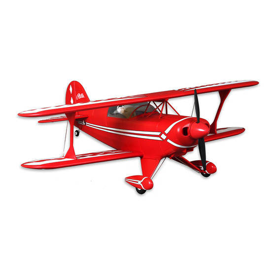
Oversized battery compartment for larger, more powerful potent competition aircraft in the lower categories. 6S packs. Built upon the successful V1 Pitts biplane, FMS is proud to • Robust and durable EPO construction. announce the brand-new Pitts V2. Redesigned with a massive 1400mm wingspan, the Pitts V2 is constructed of lightweight and robust EPO foam material. -
Page 5: Model Assembly
Model assembly Main landing gear assembly 1.Apply screw nuts to the plastic parts as shown. M3 screw nut KA2.0*8mm 2. With the fuselage inverted, install the landing gear assembly and retainer then secure it with screws as shown in the diagram. HKM3.0*20mm Lower wing assembly HKM3.0*10mm... - Page 6 Model assembly Installation of the horizontal and vertical stabilizers HKM3.0*10mm 1. Install the horizontal stabilizer into the fuselage cutout and secure the assembly with screws. HKM3.0*10mm 2. Align the vertical stabilizer with the horizontal stabilizer and push the surface down and forward until it is held securely in place.
- Page 7 Model assembly 2. Install the pushrod to the control horn on the horizontal stabilizer as shown. Installation of the horizontal stabilizer struts 1. Connect the horizontal stabilizer and the fuse- lage using the included horizontal stabilizer struts by sliding them into place. Upper wing installation 1.
- Page 8 Model assembly HKM3.0*10mm 2. Install the wing spar between the two upper wing halves. 3. Secure the upper wing onto the mounting bracket by using the included screws and retainer as shown in the diagram. 4. Once both wing halves are aligned, push the inter- plane strut rearwards to lock the structure.
-
Page 9: Battery Installation
Battery installation 1.Pull back on the latch and remove the battery hatch. 2.Apply the hook tape to the cable end of the battery. 3.Slide the full charged battery into the battery compartment with the power supply cable toward the rear end of the plane. Note: The center of gravity can be adjusted by moving the battery forward or aft.Having the correct center of gravity is critical to achieving proper flight characteristics. - Page 10 Transmitter and model setup Before getting started, bind your receiver with your transmitter. Bank left Please refer to your transmitter manual for proper operation. CAUTION: To prevent personal injury, DO NOT install the propel- ler assembly onto the motor shaft while testing the control surfac- es.
-
Page 11: Clevis Installation
Clevis installation 1.Pull the tube from the clevis to the linkage. 2.Carefully spread the clevis, then insert the clevis pin into the desired hole in the control horn. 3.Move the tube to hold the clevis on the control horn. Control horn and servo arm settings More control throw Horns Arms... -
Page 12: Before Flying The Model
Before flying the model Flying course Find a suitable flying site Take off While applying power, slowly steer to keep the model straight. Find a flying site clear of buildings, trees, power lines and The model should accelerate quickly. As the model gains flight other obstructions. -
Page 13: Troubleshooting
Trouble shooting Problem Possible Cause Solution Aircraft will not respond to -Lower throttle stick and throttle trim to lowest settings. -ESC is not armed. the throttlebut responds to -Reverse throttle channel on transmitter. -Throttle channel is reversed. other controls. -Damaged spinner, propeller, -Replace damaged parts.
Need help?
Do you have a question about the Pitts 1400 mm and is the answer not in the manual?
Questions and answers