
Related Manuals for FMS J-3 V3


Summary of Contents for FMS J-3 V3
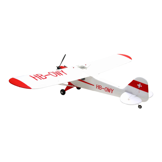
- Page 1 1400mm J-3 V3 Instruction Manual Bedienungsanleitung Manuel d’utilisation 操作手册 FLOAT RIGID STABLE Optional float Strong durable EPO Smooth flying performance...
- Page 2 WARNING WARNING: Read the ENTIRE instruction manual to become familiar with the features of the product before operating. Failure to operate the product correctly can result in damage to the product,personal property and cause serious injury. This is a sophisticated hobby product and NOT a toy. It must be operated with caution and common sense and failure to do so could result in injury or damage to the product or other property.
-
Page 3: Table Of Contents
Kit contents ····· ·························································3 others, are replicated in loving detail. Something worth noting is Model assembly ·······················································4 that FMS has made scale floats for the Cub as a response to Battery installation ············································· ····· ······ 9 ·· popular demand from the community. -
Page 4: Model Assembly
Model assembly Landing gear set installation PA2.6*15 1.With the fuselage bottom facing up, carefully Install the landing gear set to the fuselage with the included screws as shown. KA2.0*8 Main wing set installation 1.Have the screws go through the supporting bar and then secure on the base. 2.Lock up the fasteners of supporting bar on fuselage as shown. - Page 5 Model assembly 4.Secure the wings on the fuselage using the included screws as shown. HKM3.0*10 5.Lock up the fasteners of supporting bar on main wing as shown. Horizontal stabilizer installation KA2.0*8 1.Secure the horizontal stabilizer using included screws as shown.
- Page 6 Model assembly Vertical stabilizer installation KA2.0*12 1.Slide vertical stabilizer in the rear of the fuselage. 2.Secure the vertical stabilizer using included screws as shown. Linkage rod installation 1.Make sure the servos are in the neutral position. Install the linkage rod to elevator control horn as shown. Secure the linkage rod in place using the included screw as shown.
- Page 7 Model assembly Tail strut installation 1.Hook the tail struts to horizontal stabilizer and vertical stabilizer as shown. Antenna installation 1.Insert the antenna as shown. Propeller installation 1.Assemble the propeller as shown.
- Page 8 Model assembly Float set installation Screws 3*4 1.Assemble the float struts to the plastic holder as shown and secure the struts with screws. HKM3.0*10 2.Secure the float set onto the bottom of fuselage using the included plastic parts and screws as shown. Notice: The connectors on both side should be attached precisely and firmly.
-
Page 9: Battery Installation
Battery installation 1.Pull back on the latch, releasing the canopy. 2.Remove the canopy, revealing the battery compartment. 3.Apply hook and loop tape to the battery. 4.Install a fully charged battery into the battery compartment, with the battery cables facing aft. Note: The center of gravity can be adjusted by moving the battery forward or aft. - Page 10 Transmitter and model setup Before getting started, bind your receiver with your transmitter. Bank left Please refer to your transmitter manual for proper operation. CAUTION: To prevent personal injury, DO NOT install the propel- ler assembly onto the motor shaft while testing the control surfac- es.
-
Page 11: Clevis Installation
Clevis installation 1.Pull the tube from the clevis to the linkage. 2.Carefully spread the clevis, then insert the clevis pin into the desired hole in the control horn. 3.Move the tube to hold the clevis on the control horn. Control horn and servo arm settings More control throw Horns Arms... -
Page 12: Before Flying The Model
Before flying the model Flying course Find a suitable flying site Take off While applying power, slowly steer to keep the model straight. Find a flying site clear of buildings, trees, power lines and The model should accelerate quickly. As the model gains flight other obstructions. -
Page 13: Troubleshooting
Trouble shooting Problem Possible Cause Solution Aircraft will not respond to -Lower throttle stick and throttle trim to lowest settings. -ESC is not armed. the throttlebut responds to -Reverse throttle channel on transmitter. -Throttle channel is reversed. other controls. -Damaged spinner, propeller, -Replace damaged parts.
Need help?
Do you have a question about the J-3 V3 and is the answer not in the manual?
Questions and answers