Advertisement
Quick Links
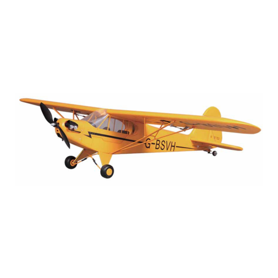
1030mm J-3 Cub
Specifications
Wingspan.................................1030mm (40.5 in)
Length......................................750 mm (29.5 in)
Weight ...................................... 540 g (19. 0 oz)
2
2
Wing Area...................................15 dm (233 in )
2
2
Wing Load .......................35.9 g/dm (0.08 oz/in )
RC System.........................................4 Channel
Advertisement

Subscribe to Our Youtube Channel
Related Manuals for FMS J-3 Cub


Summary of Contents for FMS J-3 Cub
- Page 1 1030mm J-3 Cub Specifications Wingspan.........1030mm (40.5 in) Length........750 mm (29.5 in) Weight ........540 g (19. 0 oz) Wing Area........15 dm (233 in ) Wing Load .......35.9 g/dm (0.08 oz/in ) RC System.........4 Channel...
- Page 2 Never lick or place any portion of your model in your mouth as it could cause serious injury or even death. FMS MODEL Friendly Reminder Thank you for purchasing a FMS MODEL product. Our goal is to provide high quality products and offer great customer service.
-
Page 3: Table Of Contents
Table of contents Table of contents ........... . . 1 Kit contents . -
Page 4: Kit Contents
Kit Contents 1. The fuselage assembly (With the motor, the canopy, the electronic parts, ESC) 2. Main wing ( With all electric device installed) 3. Horizontal stabilizer with elevator joiner installed 4. landing gear set 5. Propeller 6. Spare parts bag 7. -
Page 5: Fuselage/Tail Assembly
Fuselage/tail assembly 1.Place the ball-linked control horn on the aileron surface. Make sure that the orientation of the ball-link is placed as shown on the picture below. (Fig.1) 2.Once aligned, secure the control horn on the aileron surface with the included screws.(Fig.2) 3.Attach the wing-brace to the attachment points on the wing. - Page 6 5.Repeat steps 1-4 for the opposing wing.(fig.9) 6.Insert the horizontal-stabilizer as shown in the picture below. Check that the control horn and ball-link are located on the starboard horizontal stabilizer (right of the fuselage). (fig.10-11)
- Page 7 7.Install the braces that hold the horizontal stabilizer in place. (fig. 12-13) 8.Secure the horizontal stabilizer by attaching PA2.0x12 screws to the top of the horizontal stabilizer. (fig.14) 9.Please secure the pushrod to the ball link while ensuring that the elevator surface is level with the rest of the horizontal stabilizer;...
- Page 8 11.Open the electronics hatch by loosening the screw shown on the picture below (fig. 17-18) 12.Route the Y-harness into the electronics hatch (Sequence: CH1-Aileron, CH2-Elevator, CH3-Throttle, CH4- Rudder); secure the electronics bay by tightening the screw (fig.19) 13.Connect the Y-harness with the 2 aileron servo leads on the wing.(fig.20) 14.Attach the wing to the fuselage by sliding the wing into the top of the clear plastic windshield.
- Page 9 16.Align the wing-brace to the bottom of the fuselage. (fig.23) 17.Align and secure the landing gear to the hard points on the fuselage; secure the wing-brace to the bottom of the fuselage. (fig. 24-25) (PA 2.6x10/2pcs) 18.Insert the propeller onto the motor hub; make sure that the molded letters on the propellers face outwards, and then attach and tighten the prop nut with the included screwdriver.
- Page 10 19.Your aircraft is now fully assembled.
-
Page 14: Flight Control
Flight control for smooth control of your aircraft,always make small control moves. All directions are described as if you were sitting in the air craft. Tips: 1. Flying faster and slower: When your aircraft is stable in the air,push thethrottle stick up to make the aircraft go faster,and pull the throttle stick back to slow down.The aircraft will climb when the throttle is in creased. -
Page 15: Assemble The Plane
Assemble the plane Check the C.G. (Center of Gravity) Center of Gravity When balancing your model , adjust the motor battery as necessary so the model is level or slightly nose down. This the correct balance point for your model. After the first flights, The CG position can be adjusted for your personal preference. - Page 19 MR106- Canopy MR107- Screws(one set) MR204-YEL Landing gear set MR301-YEL Sticker MR302-YEL Motor Mount MR303-YEL Cowl MR304 Motor Board MR305 Propeller Nut FMSSER9GP Servo FMS-Motor-KV1700 Brushless Motor FMS-ESC-20A Brushless ESC Note:All of the parts are painted with no decal applied.
-
Page 20: Spare Parts List Content
Spare parts list content MR101-YEL MR102-YEL MR103-YEL MR104YEL MR105 MR106 MR107 MR204-YEL MR301-YEL MR302-YEL MR303-YEL MR304... -
Page 21: Charging The Flight Battery
MR305 FMSSER9GP FMS-Motor-KV1700 FMS-ESC-20A Charging the Flight Battery The Battery Charger is designed to safely charge the Li-Po battery, Caution: All instructions and warnings must be followed exactly. Mishandling of Li-Po batteries can result in fire, personal injury, or property damage. - Page 29 w w w . fm s m o d e l .c o m h t t p : / / w w w .f a c e b o o k . c o m / F M S m o d e l...
Need help?
Do you have a question about the J-3 Cub and is the answer not in the manual?
Questions and answers