Table of Contents

Advertisement

Quick Links

OPERATOR'S MANUAL
MODELS
BX1880-AU
BX2380-AU
BX2680-AU
1AGAJBMAP0940
AUX. valve equipped machine
READ AND SAVE THIS MANUAL

Advertisement

Table of Contents
loading
Need help?

Need help?

Do you have a question about the BX1880-AU and is the answer not in the manual?
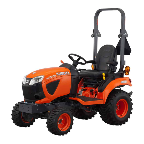
Questions and answers

Subscribe to Our Youtube Channel

Summary of Contents for Kubota BX1880-AU

  • Page 1 OPERATOR'S MANUAL MODELS BX1880-AU BX2380-AU BX2680-AU 1AGAJBMAP0940 AUX. valve equipped machine READ AND SAVE THIS MANUAL...
  • Page 2 ABBREVIATION LIST Abbreviations Definitions 2-Wheel Drive 4-Wheel Drive American Petroleum Institute ASABE American Society of Agricultural and Biological Engineers, USA ASTM American Society of Testing and Materials, USA Deutsches Institut für Normung, GERMANY Dual Traction [4WD] Feet Per Minute Hi-Lo High Speed-Low Speed Hydrostatic Transmission Meters Per Second...
  • Page 3 UNIVERSAL SYMBOLS As a guide to the operation of your tractor, various universal symbols have been utilized on the instruments and controls. The symbols are shown below with an indication of their meaning. Safety Alert Symbol Slow Read Operator's Manual Fast Hour meter/Elapsed Operating Hours Brake...
  • Page 4 You are now the proud owner of a KUBOTA Tractor. This tractor is a product of KUBOTA's quality engineering and manufacturing. It is made of the excellent materials and under rigid quality control systems. It will give you long, satisfactory service.
  • Page 5: Table Of Contents

    CONTENTS SAFE OPERATION........................5 SERVICING OF THE TRACTOR ....................17 DEALER SERVICE ............................. 17 1. Warranty of the tractor ..........................18 2. Scrapping the tractor and its procedure ....................18 SPECIFICATIONS........................19 SPECIFICATION TABLE............................. 19 TRAVELING SPEEDS TABLE ..........................21 IMPLEMENT LIMITATIONS.......................22 IMPLEMENT LIMITATION TABLES ........................22 FRONT LOADER ..............................
  • Page 6 1. Folding the ROPS............................42 2. Raising the ROPS to upright position ......................43 3. Adjusting the foldable ROPS ........................44 STARTING THE TRACTOR..........................44 STOPPING THE TRACTOR ..........................46 CHECK DURING DRIVING ..........................47 1. Cases to stop the engine immediately....................... 47 2.
  • Page 7 WHEEL TREAD ..............................66 1. Front wheels .............................. 67 2. Rear wheels............................... 68 BALLAST ................................69 1. Front ballast ............................... 69 2. Rear ballast ............................... 69 MAINTENANCE .........................71 SERVICE INTERVALS............................71 LUBRICANTS, FUEL, AND COOLANT TABLE ....................73 1. Biodiesel fuel (BDF)........................... 75 PERIODIC SERVICE .........................77 HOW TO OPEN THE HOOD ..........................
  • Page 8 SERVICE EVERY 1500 HOURS ........................92 1. Checking the injection pressure of the fuel injection nozzle ..............92 SERVICE EVERY 2000 HOURS OR 2 YEAR ....................92 1. Flushing the cooling system and changing the coolant ................92 2. Antifreeze ..............................93 SERVICE EVERY 3000 HOURS ........................
  • Page 9: Safe Operation

    2. Precautions for CAB and ROPS 1. General precautions KUBOTA recommends the use of a CAB or roll-over- • Pay special attention to the safety labels on the protective-structures (ROPS), and seat belt in almost tractor.
  • Page 10 SAFE OPERATION • Always use the seat belt if the tractor is equipped • Do not operate or idle the engine in a non- with a CAB or ROPS. ventilated area. Carbon monoxide gas is colorless, Do not use the seat belt if a foldable ROPS is down odorless, and deadly.
  • Page 11 SAFE OPERATION • Always sit in the operator's seat when you are suddenly. Do not move the steering wheel operating levers or controls. suddenly. • Do not stand between the tractor and the • Avoid changing the gears speed when the tractor is implement or trailed vehicle unless parking brake is climbing or going down a slope.
  • Page 12 SAFE OPERATION (1) Safety chain (1) Brake pedal (B) Push down parking brake (2) Parking brake pedal pedal while depressing • Set the implement-lowering-speed-knob in the lock (A) Depress brake pedal position to hold the implement in the raised • Make sure that the tractor has come to a complete position.
  • Page 13 SAFE OPERATION PRECAUTIONS FOR • When operating stationary PTO-driven- equipment, always apply the parking brake of SERVICING THE TRACTOR tractor and place the chocks behind and in front of the rear wheels. Stay clear of all rotating parts. Before servicing the tractor, follow the following Never step over rotating parts.
  • Page 14 • Make sure that the wheel bolts have been tightened people, pets, and wildlife. Please dispose properly. to the specified torque. See your local recycling center or KUBOTA Dealer (See WHEEL TREAD on page to learn how to recycle or get rid of waste products.
  • Page 15 SAFE OPERATION SAFETY LABELS BX1880, BX2380, BX2680...
  • Page 16 SAFE OPERATION BX1880, BX2380, BX2680...
  • Page 17 SAFE OPERATION BX1880, BX2380, BX2680...
  • Page 18 SAFE OPERATION BX1880, BX2380, BX2680...
  • Page 19 • Replace damaged or missing safety labels with new safety labels from your local KUBOTA Dealer. • If a component with safety label(s) attached is replaced with new component, make sure that new safety label(s) is (are) attached in the same location(s) as the replaced component.
  • Page 20 SAFE OPERATION BX1880, BX2380, BX2680...
  • Page 21: Servicing Of The Tractor

    KUBOTA Dealer. For service, contact the KUBOTA Dealership from which you purchased your tractor or your local KUBOTA Dealer. When in need of parts, be prepared to give your dealer the serial numbers of both the tractor and the engine.
  • Page 22: Warranty Of The Tractor

    BX2680 (4) Engine serial number 1. Warranty of the tractor This tractor is warranted under the KUBOTA Limited Express Warranty, a copy of which may be obtained from your selling dealer. No warranty shall, however, apply if the tractor has not...
  • Page 23: Specifications

    Model BX1880 BX2380 BX2680 10.2 kW 13.2 kW 14.5 kW PTO power (13.7 HP) (17.7 HP) (19.5 HP) Maker KUBOTA Model D722 D902 D1005 Type Liquid-cooled, 4-cycle diesel Number of cylinders 67x68 mm 72x73.6 mm 76x73.6 mm Bore and stroke (2.64x2.68 in.)
  • Page 24 (Front) Type SAE 1-3/8, 6 splines Rear PTO Revolution STD (540 rpm) Type USA No.5 (KUBOTA 10-tooth) involute spline Mid PTO Revolution STD (2500 rpm) The company reserves the right to change the specifications without notice. Manufacturer's estimate SAE J1995...
  • Page 25: Traveling Speeds Table

    TRAVELING SPEEDS TABLE SPECIFICATIONS TRAVELING SPEEDS TABLE Model BX1880 BX2380 and BX2680 Tire size (Rear) 24x12.00-12 26x12.00-12 Speed control pedal Range gear shift lever (At max engine rpm) 0 km/h to 6.0 km/h 0 km/h to 6.5 km/h 0 mph to 3.7 mph 0 mph to 4.0 mph Forward 0 km/h to 12.5 km/h...
  • Page 26: Implement Limitations

    Preceding implements may result in malfunctions or failures of the tractor, damage to other property, and injury to the operator or others. NOTE : KUBOTA does not cover any malfunctions or failures of the tractor resulting from use with improper implements by the warranty. Model...
  • Page 27 IMPLEMENT LIMITATIONS • Strictly follow the instructions outlined in the operator’s manual of the mounted or trailed machinery or trailer, and do not operate the combination tractor-machine or tractor-trailer unless all instructions have been followed. • When you use the forestry application, there are following hazards: –...
  • Page 28 IMPLEMENT LIMITATIONS Implement weight list Implement Remarks BX1880 BX2380 and BX2680 137 cm 152 cm Max. cutting width (54 in.) (60 in.) Mid-mount 95 kg 134 kg Max. weight (210 lbs) (295 lbs) 107 cm 122 cm Max. cutting width (42 in.) (48 in.) Rotary-Cutter (1 Blade)
  • Page 29 IMPLEMENT LIMITATIONS Implement Remarks BX1880 BX2380 and BX2680 160 kg 160 kg Max. weight (353 lbs) (353 lbs) Snow blower (Front) Sub frame Necessary Necessary 114 cm 114 cm Post hole digger Digging depth (45 in.) (45 in.) 119 cm 119 cm Rotary broom Cleaning width...
  • Page 30: Front Loader

    IMPLEMENT LIMITATIONS FRONT LOADER FRONT LOADER Check the fixed points on the body of the tractor where the front loader must be installed. Install the frame of front loader to the frame of tractor as shown in the following figures. Location Bolt/Nut Required Torque...
  • Page 31: Instrument Panel And Controls

    INSTRUMENT PANEL, SWITCHES, AND HAND CONTROLS INSTRUMENT PANEL AND CONTROLS INSTRUMENT PANEL AND CONTROLS INSTRUMENT PANEL, SWITCHES, AND HAND CONTROLS ™ Easy Checker ................47 Coolant temperature gauge ............48 Tachometer ..................49 Hour meter..................49 Hazard light switch................. 28 Key switch..................
  • Page 32: Key Switch

    INSTRUMENT PANEL AND CONTROLS INSTRUMENT PANEL, SWITCHES, AND HAND CONTROLS 1. Key switch (1) Head light switch (B) Off (A) On (A) Off (C) Preheat (B) On (D) Start 4. Hazard light switch 1. When pressing the hazard-light-switch, the hazard 2.
  • Page 33: Hood Open Lever

    INSTRUMENT PANEL, SWITCHES, AND HAND CONTROLS INSTRUMENT PANEL AND CONTROLS (1) Turn signal light switch (B) Left turn (A) Right turn 6. Hood open lever The hood-open-lever is the lever to open the hood. WARNING To avoid serious injury or death from contact with moving parts: •...
  • Page 34: Foot Controls And Hand Controls

    INSTRUMENT PANEL AND CONTROLS FOOT CONTROLS AND HAND CONTROLS FOOT CONTROLS AND HAND CONTROLS Brake pedal..................31 Hand accelerator lever..............33 Brake pedal..................32 (10) Speed control pedal............... 33 Parking brake lock pedal ............... 31 (11) Auxiliary hydraulic control lever (if equipped) ........ 63 Parking brake lock pedal ...............
  • Page 35: Operator's Seat

    FOOT CONTROLS AND HAND CONTROLS INSTRUMENT PANEL AND CONTROLS 1. Operator's seat When operating the hydraulic-control-lever, open the arm rest RH up to 130 deg. Opening the arm rest RH up to 130 deg. will prevent your elbow from hitting the WARNING arm rest RH.
  • Page 36: How To Use The Parking Brake

    INSTRUMENT PANEL AND CONTROLS FOOT CONTROLS AND HAND CONTROLS • Engage 4-wheel drive when traveling down a 4. Range gear shift lever (Hi-Lo) slope. You can shift the range-gear-shift-lever only when tractor is completely stopped. WARNING To avoid serious injury or death: •...
  • Page 37: Hand Accelerator Lever

    FOOT CONTROLS AND HAND CONTROLS INSTRUMENT PANEL AND CONTROLS • Do not engage the front-wheel-drive when traveling at road speed. • When driving on icy, wet, or loose surfaces, make sure that the tractor is correctly ballasted to avoid skidding and loss of steering control. Operate the tractor at reduced speed and engage the front-wheel-drive.
  • Page 38: Speed Set Device [Bx2380 And Bx2680]

    INSTRUMENT PANEL AND CONTROLS FOOT CONTROLS AND HAND CONTROLS the tractor is equipped with the operator- presence-control-system (OPC). 8. Speed set device [BX2380 and BX2680] The speed-set-device is designed for tractor-operating- efficiency and operator's comfort. Speed-set-device will provide a constant forward operating speed by mechanically holding the speed-control-pedal at a selected position.
  • Page 39: Accessory Box

    ACCESSORY INSTRUMENT PANEL AND CONTROLS 4. Glove box [BX2380 and BX2680] (1) 12V electric outlet (1) Glove box 2. Accessory box (1) Accessory box NOTE : • The inside of the accessory box is not completely water-proof nor dust-proof. When you keep valuables in the accessory box, be careful not to wet nor dirty it.
  • Page 40: Pre-Operation Check

    PRE-OPERATION CHECK DAILY CHECK ITEMS BEFORE OPERATION OF THE TRACTOR PRE-OPERATION CHECK DAILY CHECK ITEMS BEFORE OPERATION OF THE TRACTOR To prevent trouble from occurring, it is important to know the condition of the tractor well. WARNING To avoid serious injury or death: •...
  • Page 41: Operating The Engine

    STARTING THE ENGINE OPERATING THE ENGINE OPERATING THE ENGINE WARNING To avoid serious injury or death: • Read and understand Safe operation in this manual. • Read and understand the safety labels located on the tractor. • To avoid the danger of exhaust-fume-poisoning, do not operate the engine in a closed building without proper ventilation.
  • Page 42 OPERATING THE ENGINE STARTING THE ENGINE 4. Place the speed-control-pedal in the neutral position. (1) Auxiliary hydraulic control (A) Lock lever (2) Lock lever (1) Speed control pedal 7. Move the hydraulic-control-lever forward (lowered (down) position) to lower the implement. NOTE : •...
  • Page 43: Cold Weather Starting Of The Engine

    STARTING THE ENGINE OPERATING THE ENGINE 9. Insert the starter key into the key switch and turn the starter key to the on position. (A) Off (D) Start (B) On (C) Preheat 10. Check the warning-indicator-lamps in the Easy (1) Turn signal/hazard light indi- (5) Coolant temperature indica- ™...
  • Page 44: Stopping The Engine

    NOTE : JUMP STARTING THE ENGINE • If the starter key does not stop the engine, consult your local KUBOTA Dealer. Follow the instructions of jump starting of the engine to safely start the engine. WARMING UP OF THE ENGINE...
  • Page 45 OPERATING THE ENGINE (1) Dead battery (3) Front bolt (2) Jumper cables (4) Helper battery 1. Bring the helper vehicle with a battery of the same voltage as the disabled tractor within easy cable reach. IMPORTANT : • The helper vehicle must not touch the disabled tractor.
  • Page 46: Operating The Tractor

    • In winter, operate the tractor after fully warming up and attachments. If interference occurs, contact the engine. your KUBOTA dealer. • Do not run the engine at speeds faster than necessary. • On rough roads, slow down to suitable speeds.
  • Page 47: Raising The Rops To Upright Position

    OPERATION OF THE FOLDABLE ROPS OPERATING THE TRACTOR 2. Remove both set pins. (1) Set pins (2) Snap pins (1) Set pins (2) Snap pins 2. Raising the ROPS to upright 3. Fold the ROPS. position CAUTION 1. Remove both snap pins and set pins. To avoid personal injury: •...
  • Page 48: Adjusting The Foldable Rops

    OPERATING THE TRACTOR OPERATION OF THE FOLDABLE ROPS 3. Align the set-pin-holes and insert both set pins. Secure the set pins with the snap pins. CAUTION To avoid personal injury: • Make sure that both set pins are properly installed as soon as the ROPS is in the upright position and secured with the snap pins.
  • Page 49 OPERATING THE TRACTOR 2. Adjust the steering wheel to proper position [BX2380 and BX2680]. CAUTION To avoid personal injury: • Do not adjust the steering wheel while the tractor is in motion. Pull the tilt lever to adjust the steering wheel. (1) Brake pedal (B) Push down parking brake (2) Parking brake lock pedal...
  • Page 50: Stopping The Tractor

    OPERATING THE TRACTOR STOPPING THE TRACTOR 6. Raise the Implement. [BX2380 and BX2680] Move the hydraulic control lever rearward (the raised (up) position). (See 1. Hydraulic control on page (1) Hydraulic control lever (C) Raised (A) Lowered (B) Neutral position 7.
  • Page 51: Check During Driving

    (1) Brake pedal (B) Push down the parking • For checking and servicing of your tractor, (2) Parking brake lock pedal brake lock pedal while de- (A) Depress pressing the brake pedal consult your local KUBOTA Dealer instructions. BX1880, BX2380, BX2680...
  • Page 52: Fuel Gauge

    (3) Preheat (7) Low fuel indicator (4) Electrical charge (8) Key switch your local KUBOTA Dealer. Once you turn off the key switch and the fuel- ™ Warning-indicator-lamps in Easy Checker gauge-system returns to normal, the needle should point to the normal position again.
  • Page 53: Dealing With The Overheated Coolant Temperature

    If the needle of the The hour meter indicates in 5 digits the hours the coolant-temperature-gauge returns to the most tractor has been used as the following table. bottom position, consult your KUBOTA Dealer. The step that the display Tractor operated hours operates 2.4 Dealing with the overheated coolant...
  • Page 54: Parking The Tractor

    OPERATING THE TRACTOR PARKING THE TRACTOR Recommended Engine Speed 2. Lower all implements to the ground. (See 1. Hydraulic control on page Implement Recommended engine speed PTO 540 Use within yellow range Loader Use within orange range (1) Hydraulic control lever (D) Slow up (A) Down (E) Up...
  • Page 55: Precautions For Operating The Tractor On A Road

    • The power steering is activated only while the Consult your local KUBOTA Dealer for further details. engine is running. While the engine is stopped, the tractor functions in the same manner as tractors without power steering.
  • Page 56 OPERATING THE TRACTOR TECHNIQUES FOR OPERATING THE TRACTOR • Turning the steering wheel all the way to the stop activates the relief valve. Do not hold the steering wheel in the stop for a long period of time. • Avoid turning the steering wheel while the tractor is stopped, or tires may wear out sooner.
  • Page 57: Pto (Power Take-Off)

    (C) Rear-PTO position See the following figure. Mid PTO To use the mid PTO, shift the PTO-select-lever to the mid PTO position and the PTO-clutch-lever to the position. The mid PTO is available for KUBOTA approved implements. BX1880, BX2380, BX2680...
  • Page 58: Pto Shaft Cover And Pto Shaft Cap

    PTO (POWER TAKE-OFF) PTO OPERATION (1) PTO clutch lever (B) Off (disengage) (1) PTO shaft cover (A) Normal position (A) On (engage) (2) PTO shaft cap (B) Raised position NOTE : 4. Using stationary PTO • The tractor engine will not start if the PTO- clutch-lever is in the engaged (on ) position.
  • Page 59: Pto Drive Shaft

    PTO OPERATION PTO (POWER TAKE-OFF) 5.1 Adjusting the length of PTO drive shaft To adjust the length of the PTO-drive-shaft, take the following instructions. 1. To adjust the inner-and-outer-guard-tubes, hold the half shafts next to each other in the shortest working position, and mark the half shafts in the shortest working position of the inner-and-outer- guard-tubes.
  • Page 60: 3-Point Hitch And Drawbar

    3-POINT HITCH AND DRAWBAR OVERVIEW OF 3-POINT HITCH AND DRAWBAR 3-POINT HITCH AND DRAWBAR OVERVIEW OF 3-POINT HITCH AND DRAWBAR (1) Top link (4) Turnbuckle (7) Lifting rod (right) (2) Lifting rod (left) (5) Lower link (8) Hitch (3) Check chains (6) Top link holder (9) Holder plate Use the holder plate to hold the lower link higher while mowing with mid-mount mower only over uneven terrain.
  • Page 61: 3-Point Hitch

    3-POINT HITCH 3-POINT HITCH AND DRAWBAR 3-POINT HITCH 3. Adjusting the top link The proper length of the top link varies according to the 1. Precautions for attaching and type of implement being used. detaching the implements to the 3- NOTE : point hitch •...
  • Page 62 3-POINT HITCH AND DRAWBAR (1) Hitch BX1880, BX2380, BX2680...
  • Page 63: Hydraulic Unit

    If you do not correct the hydraulic control unit, it will be damaged. 3. Operate the engine at low idle speed for the Contact your KUBOTA Dealer for adjustment. following seconds to bleed air from the system. Operating the hydraulic control lever actuates the...
  • Page 64: Auxiliary Hydraulics

    When implement is attached, follow the following procedure. 1. Remove the block cover. 2. Attach the block outlet cover (option). The block outlet cover is standard part for KUBOTA Implements 3. Route the implement inlet, outlet, and return pipes as shown in the figures.
  • Page 65: Mower Lift Linkage System

    MOWER LIFT LINKAGE SYSTEM HYDRAULIC UNIT MOWER LIFT LINKAGE SYSTEM 1. Cutting height control dial When mounting the Mid-mount mower, turn the cutting- height-control-dial to the desired height. For further details, refer to the following operator's manuals of rotary mower. •...
  • Page 66: Hydraulic Control Unit Use Reference Chart

    HYDRAULIC UNIT MOWER LIFT LINKAGE SYSTEM 2. Hydraulic control unit use reference chart In order to use the hydraulics properly, the operator must know the following chart. Though this information may not be applicable to all types of implements and soil conditions, it is useful for general conditions. (1) Check chains (1) Hydraulic control lever Implement...
  • Page 67: Auxiliary Hydraulic Control Valve

    AUXILIARY HYDRAULIC CONTROL VALVE HYDRAULIC UNIT AUXILIARY HYDRAULIC 2. Auxiliary hydraulic ports CONTROL VALVE The auxiliary hydraulic ports are equipped with quick couplers. If you do not use the auxiliary hydraulic ports, place the WARNING dust plugs on the quick couplers ends. To avoid serious injury or death: •...
  • Page 68: Controlling Loader (Only If Equipped With Loader)

    HYDRAULIC UNIT AUXILIARY HYDRAULIC CONTROL VALVE Hydraulic outlet ports of first segment Colored Coupler Hydraulic Cylinder port Lever Backward Forward Blue and yellow Head-End side White and red Rod-End side White Port NOTE : Yellow • If you move the auxiliary-hydraulic-control- lever to the float position, it will be held there by the detent mechanism.
  • Page 69 AUXILIARY HYDRAULIC CONTROL VALVE HYDRAULIC UNIT the connector lines is released so the loader will go down by its own weight. This lever position after the bump is the second stage. When the operator lets the hand off from the auxiliary-hydraulic-control- lever, it will stay in the second stage position.
  • Page 70: Tires, Wheels, And Ballast

    • Do not use tires other than those approved by Front 18x8.50-10 Bar (1.5 kgf/cm [22 psi] KUBOTA. • When you intend to mount different size of tires 150 kPa from equipped ones, consult your dealer about 18x8.50-10 Ind. (1.5 kgf/cm [22 psi] front drive gear ratio for details.
  • Page 71: Front Wheels

    WHEEL TREAD TIRES, WHEELS, AND BALLAST Models BX1880 BX2380 and BX2680 18x8.50-10 Turf, 16x7.50-8 Turf, 16x7.50-8 Tire 18x8.50-10 Bar, 18x8.50-10 Ind. Tread (1) Bolt Tightening torques 149 N⋅m to 179 N⋅m (A) 930 mm Front (15.2 kgf⋅m to 18.3 kgf⋅m) (36.6 in.) [110 lbf⋅ft to 132 lbf⋅ft] 109 N⋅m to 130 N⋅m...
  • Page 72: Rear Wheels

    TIRES, WHEELS, AND BALLAST WHEEL TREAD 2. Rear wheels IMPORTANT : • Do not the turn rear discs to obtain wider tread. • Always attach tires as shown in the figures in the following table. If you not attach the rear wheel as illustrated in the table, transmission parts may be damaged. You can not adjust width of the rear tread.
  • Page 73: Ballast

    Front end weights (option) The front end weights can be attached to the bumper. Refer to your implement operator's manual for required number of weights or consult your local KUBOTA Dealer to use it. NOTE : • Besides the weight, a front weight bracket and mounting bolt kit(s) are required for mounting the weight.
  • Page 74 TIRES, WHEELS, AND BALLAST BALLAST Liquid ballast in rear tires • To avoid damage to the transmission, do not The weight should be added to the tractor in the form of use rear wheel weights and liquid ballast at the liquid ballast.
  • Page 75: Maintenance

    SERVICE INTERVALS MAINTENANCE MAINTENANCE SERVICE INTERVALS Indication on hour meter Ref. Items Since then page 50 100 150 200 250 300 350 400 450 500 550 600 650 700 Engine oil Change ◎ ○ ○ ○ every 200 Hr Engine oil filter Replace ○...
  • Page 76 • The items which is @ marked are registered as the emission-related-critical-parts by KUBOTA in the U.S.EPA nonroad emission reg- ulation. As the engine owner, you are responsible for the performance of the required maintenance on the engine according to the preceding instruction.
  • Page 77: Lubricants, Fuel, And Coolant Table

    Oil amount when the oil level is at the upper level of the oil level gauge. The product name of KUBOTA genuine UDT fluid may be different from that in the operator's manual depending on countries or territories. Consult your local KUBOTA Dealer for further detail.
  • Page 78 For an enhanced ownership experience, we recommend Super UDT-2 to be used instead of standard hydraulic/ transmission fluid. Super UDT-2 is a proprietary KUBOTA formulation that delivers superior performance and protection in all operating conditions. Regular UDT is also permitted for use in this machine.
  • Page 79: Biodiesel Fuel (Bdf)

    D7467 standard, as revised, without adversely during cold weather conditions. affecting the performance and durability of the • The KUBOTA warranty, as specified in the Owner's engine and the components of the fuel system. Warranty Information Guide, only covers flaws in •...
  • Page 80 Fuel hose damage occurred. Consult your local Replace Every 2 years KUBOTA Dealer for this service. Long term storage for B5 • BDF easily deteriorates due to oxygen, water, heat, and foreign substances. Do not store B5 longer than 3 months.
  • Page 81: Periodic Service

    HOW TO OPEN THE HOOD PERIODIC SERVICE PERIODIC SERVICE Take the following precautions when checking the WARNING tractor. • Park the machine on firm and level ground. To avoid serious injury or death: • Set the parking brake. • Do not work under any hydraulically supported •...
  • Page 82: Checking The Engine Oil Level

    PERIODIC SERVICE DAILY CHECK Using fuel 7. If the engine-oil-level is too low, add new engine oil to the prescribed level at the oil inlet. Temperature fuel (See LUBRICANTS, FUEL, AND COOLANT TABLE Above -10 ℃ (14 ℉) Grade No.2-Diesel fuel on page Below -10 ℃...
  • Page 83: Checking The Coolant Level

    • Use clean, fresh, soft water and antifreeze to fill the recovery tank. • If water should leak, consult your local KUBOTA Dealer. 1. Check to see that the coolant level is between the [H] and [L] marks of the recovery tank.
  • Page 84: Checking The Brake Pedal

    PERIODIC SERVICE DAILY CHECK 2. Detach the radiator screen, and then remove all the 9. Checking the head light, hazard foreign material. light, and so on NOTE : 1. Inspect the lights such as the head light, hazard • If the dust or chaff is accumulated in the light, and so on for broken bulbs and lenses.
  • Page 85: Checking The Movable Parts

    • Check the instrument panel for correct operation of the switches and the gauges. Consult your KUBOTA Dealer regarding maintenance, diagnosis, and repair. 12. Checking the movable parts 1. If any of the movable parts, such as levers and...
  • Page 86: Checking The Engine Start System

    3. Turn the key to the start position. 4. Make sure that the engine does not crank. 5. If the engine cranks, consult your local KUBOTA Dealer. Test of switch for the PTO clutch lever 1. Make sure that the range-gear-shift-lever is set in the neutral [N] position.
  • Page 87: Checking The Wheel Bolt Torque

    4. Make sure that the engine shuts off after approximately 1 second. 5. If the engine does not stop, consult your local Rear KUBOTA Dealer. Test of switches for the operator's seat and the PTO clutch lever 1. Start the engine.
  • Page 88: Cleaning The Lock Lever Shaft

    PERIODIC SERVICE SERVICE EVERY 50 HOURS 5. Cleaning the lock lever shaft IMPORTANT : • The factory-installed battery is of non-refillable 1. Before you use the lock lever, clean the lever- type. If the battery is weak, charge the battery or movable-area (1).
  • Page 89: Dealing With The Battery When Storing The Tractor For A Long Period

    SERVICE EVERY 100 HOURS PERIODIC SERVICE • Never check the battery charge by placing a • Be sure to stop the engine and remove the key metal object across the posts. before cleaning the air cleaner element. Use a voltmeter or hydrometer. IMPORTANT : •...
  • Page 90: Checking The Fuel Filter

    PERIODIC SERVICE SERVICE EVERY 100 HOURS BX1880 and BX2380 2. After inspection of the fuel filter, if the fuel line and clamps are found damaged or deteriorated, replace them. 3. Check the fuel filter. If the fuel filter is clogged by debris or contaminated by water, replace it.
  • Page 91: Adjusting The Hst Neutral Spring For Speed Control Pedal

    KUBOTA dealer. The HST-neutral-spring located under the front right side of the fender can adjust returning speed of the speed-control-pedal. • Consult your local KUBOTA Dealer for service. (1) HST neutral spring (2) Adjusting nut BX1880, BX2380, BX2680...
  • Page 92: Service Every 200 Hours

    IMPORTANT : 3. Fill the engine with the new engine oil up to the • To prevent serious damage to the engine, use upper notch on the dipstick. only a KUBOTA genuine filter. (See LUBRICANTS, FUEL, AND COOLANT TABLE on page 1.
  • Page 93: Replacing The Transmission Oil Filter

    IMPORTANT : • To prevent serious damage to the hydraulic system, use only a KUBOTA genuine filter. 1. Remove the transmission oil filter. 2. Put a film of clean transmission oil on rubber seal of new transmission oil filter.
  • Page 94: Adjusting The Toe-In

    WARNING To avoid serious injury or death: • Oil can be hot and can burn. Allow the engine to cool down sufficiently. Transmission fluid KUBOTA SUPER UDT 2 11.3 L (1) Lock nuts (2) Tie-rod Transmission fluid capacity (3.0 U.S.gals.) 1.
  • Page 95: Cleaning The Transmission Strainer

    SERVICE EVERY 400 HOURS PERIODIC SERVICE 2. After draining the transmission fluid, reinstall the When reassembling the transmission strainer, be drain plug. careful not to damage the parts. 3. Clean the transmission strainer. 4. Fill with new transmission fluid up to the upper notch on the dipstick.
  • Page 96: Replacing The Fuel Filter Element

    10 minutes after filling with Checking the front axle case oil level new front axle case oil • Consult your local KUBOTA Dealer for checking the injection pressure of the fuel injection nozzle. 7. After filling with front-axle-case-oil, reinstall the oil gauge and breather plugs.
  • Page 97: Antifreeze

    SERVICE EVERY 2000 HOURS OR 2 YEAR PERIODIC SERVICE BX1880 and BX2380 2.9 L BX1880 (3.1 U.S.qts.) Coolant capacity (with recovery 3.1 L BX2380 tank) (3.3 U.S.qts.) 3.3 L BX2680 (3.5 U.S.qts.) 1. Stop the engine and let it cool down. 2.
  • Page 98: Service Every 3000 Hours

    KUBOTA engines. 1. Checking the injection pump Consult your local KUBOTA Dealer concerning coolant for extreme conditions. • Consult your local KUBOTA Dealer for checking the injection pump. NOTE : • The following data represent industry standards...
  • Page 99: Checking The Radiator Hoses And The Hose Clamps

    SERVICE EVERY 1 YEAR PERIODIC SERVICE 2. If the hose and the clamps are found worn or damaged, replace or repair them at once. BX1880 and BX2380 (1) Radiator hoses (2 pcs) (2) Hose clamps (4 pcs) 3. Checking the power steering line BX2680 WARNING To avoid serious injury or death:...
  • Page 100: Checking The Engine Breather Hose

    • Consult your local KUBOTA Dealer for checking the prevent dust and dirt from entering. You must engine breather hose. take particular care of the fuel lines in order to avoid dust and dirt getting into the fuel system.
  • Page 101: Service As Required

    See ENGINE 50 A Check circuit against wrong battery connection TROUBLESHOOTING on page 100 or contact your local KUBOTA Dealer specific information dealing with electrical problems. BX1880, BX2380, BX2680...
  • Page 102: Replacing The Light Bulb

    PERIODIC SERVICE SERVICE AS REQUIRED 3. Replacing the light bulb Light Capacity Head light 37.5 W×2 Tail light 12.8 W×2 Hazard light 27 W×2 Head light 1. Take the light bulb out of the body of the light and replace with a new one. Other lights 1.
  • Page 103: Storage Of The Tractor

    STORING THE TRACTOR STORAGE OF THE TRACTOR STORAGE OF THE TRACTOR Keep the tires out of direct sunlight and extreme WARNING heat. To avoid serious injury or death: • Do not clean the tractor while the engine is REMOVING THE TRACTOR running.
  • Page 104: Troubleshooting

    Coolant flow route corroded. • Flush the cooling system. Engine does not stop when key switch is • Fuse blown (15 A). • Replace the fuse. turned off. If you have any questions, consult your local KUBOTA Dealer. BX1880, BX2380, BX2680...
  • Page 105: Options

    OPTION ITEMS OPTIONS OPTIONS OPTION ITEMS Consult your local KUBOTA Dealer for further details of the following options. • 16 x 7.5-8 Bar Tire [BX1880] • 24 x 12.0-12 Bar Tire [BX1880] • 18 x 8.5-10 Bar Tire [BX2380 and BX2680] •...
  • Page 106: Index

    INDEX Symbols coolant changing..............92 12 V electric outlet............34 checking the level..........79 3-point hitch coolant table..............73 lowering speed............59 coolant temperature overview..............56 overheating............49 precautions for attaching and detaching the coolant temperature gauge......... 48 implements............57 cooling system 3-point hitch control system........59 flushing..............92 cutting height control dial..........
  • Page 107 front axle case oil changing..............91 implement limitation table..........22 front axle pivot injection pump adjusting..............90 checking..............94 front ballast..............69 instrument panel............27 front loader..............26 intake air line front wheel drive lever..........32 checking..............94 front wheels..............67 replacing..............96 fuel checking amount........... 77 fuel filter checking..............
  • Page 108 operating the PTO...........8 storing operating the tractor on a road......51 tractor..............99 operating the tractor on a slopes and rough terrain.. switches..............27 ................ 51 operating the tractor on slopes........7 parking the tractor........... 8 tachometer..............49 safety for children............7 the foldable ROPS servicing the tractor..........9 adjusting..............44 starting to operate the tractor........
  • Page 109 KUBOTA Corporation is ... Since its inception in 1890, KUBOTA Corporation has grown to rank as one of the major firms in Japan. To achieve this status, the company has through the years diversified the range of its products and services to a remarkable extent.
  • Page 110 Thailand : SIAM KUBOTA CORPORATION CO., LTD. 101/19-24 Moo 20, Navanakorn Industrial Estate, Tambon Khlon nuen , Amphur Khlon luan , Pathumthani 12120, THAILAND Telephone : (66)2-909-0300 Korea : KUBOTA KOREA CO., LTD. 41-27, Jayumuyeok- il, Baeksan-myeon, Gimje-si, Jeollabuk-do, Korea Telephone : (82)-63-544-5822 India : KUBOTA AGRICULTURAL MACHINERY INDIA PVT. LTD. No.15, Medavakkam Road, Sholin anallur, Chennai-600119, T.N., India Telephone : (91)44-6104-1500 Vietnam : KUBOTA VIETNAM CO., LTD. Lot B-3A2-CN, My Phuoc 3 Industrial Park, Ben Cat District, Binh Duon  Province, Vietnam Telephone : (84)-650-3577-507 KUBOTA Corporation AV. I. 1-1. -. K Code No. K2874-7131-1 © PRINTED IN U.S.A. KUBOTA Corporation 2017...

This manual is also suitable for:

Bx2380-auBx2680-au

Table of Contents