Table of Contents
Advertisement
Quick Links
;
For identification of product codes, refer to Table 1. See "Table 1 - Product Specifications" for more product information.
X
Lanyard Style
(Figure 2)
1246518
A
1246519
1246524
1246525
1246526
1246527
B
1246529
1246530
1246532
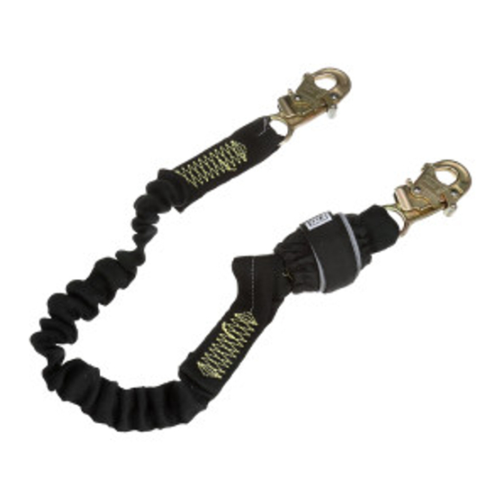
Figure 1
Lanyard Style (see Figure 1 for callouts)
Reference
A
X
B
X
;
Refer to the product label for capacity information and performance data specific to your lanyard model.
OSHA 1910.140
ANSI Z359.13-2013
OSHA 1926.502
Figure 1 - Product Overview
Model
Figure 2 - Lanyard Styles
L
Length (L)
6.0 ft. (1.83 m)
6.0 ft. (1.83 m)
6.0 ft. (1.83 m)
6.0 ft. (1.83 m)
6.0 ft. (1.83 m)
6.0 ft. (1.83 m)
6.0 ft. (1.83 m)
6.0 ft. (1.83 m)
6.0 ft. (1.83 m)
Capacity
130 lb. - 310 lb.
(59 kg - 140 kg)
Z
Y
130 lb. - 310 lb.
Z
Y
(59 kg - 140 kg)
3M
DBI-SALA
TM
Energy-Absorbing Lanyards
USER INSTRUCTIONS
5908119 Rev. A
Z
Lanyard Leg
Material (Z)
KW1
KW1
KW1
KW1
KW1
KW1
KW1
KW1
KW1
Energy
Maximum
Absorber
Free Fall
6 ft.
Tear Web
(1.83 m)
6 ft.
Tear Web
(1.83 m)
®
Y
Connectors
X
Y
C1
C1
CL
C1
C1
C4
C5
C3
C5
C6
C5
C2
CL
C6
CL
C3
CL
C2
Average
Arrest Force
900 lbf
(4 kN)
900 lbf
(4 kN)
© 3M 2022
Advertisement
Table of Contents

Related Manuals for 3M DBI-SALA 1246518


Summary of Contents for 3M DBI-SALA 1246518
- Page 1 (4 kN) 130 lb. - 310 lb. 6 ft. 900 lbf Tear Web (59 kg - 140 kg) (1.83 m) (4 kN) Refer to the product label for capacity information and performance data specific to your lanyard model. © 3M 2022...
-
Page 2: Safety Information
Ensure use of your product is rated for the hazards present in your work environment. Ensure there is sufficient fall clearance when working at height. Never modify or alter your Fall Protection equipment. Only 3M, or persons authorized in writing by 3M, may make repairs to 3M equipment. -
Page 3: Product Overview
Always ensure you are using the latest revision of your 3M instruction manual. Visit www.3m.com/userinstructions or contact 3M Technical Services for updated instruction manuals. PRODUCT OVERVIEW: Figure 1 lists the 3M™ DBI-SALA Energy-Absorbing Lanyard models covered by this instruction. Energy-absorbing lanyards are ®... -
Page 4: Component Specifications
Before using this equipment, record the product identification information from the ID label in the ‘Inspection and Maintenance Log’ at the back of this manual. Table 1 – Product Specifications System Specifications: Anchorage: Anchorage structure requirements vary with the system application and whether it is a certified anchorage or non-certified anchorage. -
Page 5: Performance Specifications
Table 1 – Product Specifications Lanyard Leg Material: Figure 1 Description Minimum Tensile Strength Reference 2.0-in. (5.08 cm) Kevlar nomex tube over 5000 lbf (22.2 kN) 1.0-in. (2.54 cm) elastic webbing Performance Specifications All energy-absorbing lanyards covered in this instruction are below 1800 lbf (8 kN) Maximum Maximum Arresting Force: Arresting Force. -
Page 6: Product Application
Hazards may include, but are not limited to: high heat, chemicals, corrosive environments, high voltage power lines, explosive or toxic gases, moving machinery, sharp edges, or overhead materials that may fall and contact the user or equipment. Contact 3M Technical Services for further clarification. - Page 7 MAKING CONNECTIONS: All connections must be compatible in size, shape, and strength. See Figure 5 for examples of inappropriate connections. Do not attach snap hooks and carabiners: To a D-ring to which another connector is attached. In a manner that would result in a load on the gate. Large-throat snap hooks should not be connected to standard- size D-Rings or other connecting elements, unless the snap hook has a gate strength of 16 kN (3,600 lbf) or greater.
-
Page 8: Installation
INSTALLATION OVERVIEW: Installing this product requires effective planning and knowledge of fall clearance requirements. In the event of a fall, there must be enough fall clearance present to safely arrest the user. PLANNING: Plan your Fall Protection system before starting your work. Account for all factors that may affect your safety before, during, and after a fall. - Page 9 FALL CLEARANCE CHARTS (MAXIMUM VALUES) Find your Required Fall Clearance (FC) by using the following charts. These charts give the most fall clearance needed for your lanyard within a specified anchorage configuration. Charts are separated by the type of lanyard you are using (see “Lanyard Style” within Figures 1 and 2).
- Page 10 CALCULATING CLEARANCE (EXACT VALUES) There are two common methods for calculating clearance requirements. The “Working Surface Method” finds Required Fall Clearance (FC), which is measured from your working platform to the next obstruction below. The “Anchorage Method” finds Total Fall Distance (TFD), which is measured from one’s anchorage point down. Both methods are acceptable for finding your clearance requirement.
- Page 11 ENERGY ABSORBER TABLES Use the below tables to find the Deceleration Distance (DD) for your lanyard. Select the chart containing information for your Lanyard Style (see Figures 1 and 2). Find your user weight (including tools, clothing, etc.). Find your corresponding Deceleration Distance (DD). If your weight is between listed values, round up to the next highest value.
- Page 12 CONNECTING TO ANCHORAGE: Figure 8 illustrates typical lanyard anchorage connections. The Anchorage (A) should be directly overhead to minimize free fall and swing fall hazards (see Section 3.3.B). Select an anchorage capable of sustaining the static loads defined in Table 1. Depending on system and product configuration, the user may secure the Anchoring Connector (B) of the lanyard directly to the anchorage structure or to an anchorage connector or anchorage connection point between.
- Page 13 INSTALLING LIFELINE SUBSYSTEMS: Lanyards with lifeline subsystems (e.g. rope grabs and cable grabs) as their anchoring connector will require special procedures for securing the lanyard to anchorage. Anchorage for lifeline subsystems should exclusively be vertical or horizontal lifelines. For more information on how to secure your lifeline subsystem, refer to the manufacturer instructions for your lifeline subsystem and lifeline.
-
Page 14: Maintenance, Service, And Storage
CLEANING: 3M product must be cleaned in accordance with 3M instructions. To clean the product, wash in a mild, bleach-free detergent and rinse with clean water. The product should afterwards be hung to air-dry. Water used for cleaning and temperatures used to air-dry must never exceed 130°F (54.4°C). -
Page 15: Labels And Markings
2) Illustration of inappropriate connections RFID Tag LOCATION: 3M product covered in these user instructions is equipped with a Radio Frequency Identification (RFID) Tag. RFID Tags may be used in coordination with an RFID Tag Scanner for recording product inspection results. See Figure 12 for where your RFID Tag is located. - Page 16 Figure 12 - RFID Tag Location Figure 13 - Product Labels AVERTISSEMENT Open label cover for use and warning information. Failure to follow manufacturer's warnings and instructions could result in serious injury or death. Soulevez le cache de l'étiquette pour voir les renseignements d'utilisation et d'avertissement. Ne pas respecter les avertissements ou les instructions du fabricant peut causer des blessures graves ou mortelles.
- Page 17 Figure 13 - Product Labels...
-
Page 18: Inspection Procedure
Table 2 – Inspection and Maintenance Log Model Number (Serial Number): Date Purchased: Date of First Use: ··· This product must be inspected by the user before each use. Additionally, a Competent Person other than the user must inspect this equipment at least once each year. ···... - Page 19 Figure 14 - Lanyard Inspection Figure 15 - Connector Inspection Figure 16 - Energy Absorber Inspection...
- Page 20 LIMITED REMEDY: Upon written notice to 3M, 3M will repair or replace any product determined by 3M to have a factory defect in workmanship or materials. 3M reserves the right to require product be returned to its facility for evaluation of warranty claims. This warranty does not cover product damage due to wear, abuse, misuse, damage in transit, failure to maintain the product or other damage beyond 3M’s control.
Need help?
Do you have a question about the DBI-SALA 1246518 and is the answer not in the manual?
Questions and answers