
Related Manuals for 3M Dynatel 1420-iD


Summary of Contents for 3M Dynatel 1420-iD
- Page 1 Dynatel ™ ™ Electronic Marking System (EMS) Marker Locator 1420-iD Operator’s Manual 1420-iD Marker Locator 1420E-iD Marker Locator September 2015 78-8130-6741-6 Rev G...
-
Page 2: Table Of Contents
A. Communicating with the GPS Device ............21 B. Capturing the GPS Coordinates (Capture Mode / Mode 1) ....... 21 C. Sending 3M iD Marker Data to GPS (Capture-Transmit Mode / Mode 2) 22 10. Help Mode ....................22 11. 3M Dynatel PC Tool Kit and Locator Software Upgrades ......22 12. - Page 3 ™ 1420E-iD are designed with all of the functionality of previous Dynatel models, with the enhanced capability to read from, and write user information into, 3M iD Markers. Information such as a pre-programmed unique identification number, facility data, application type, placement date and other details can all be read, stored and downloaded to your PC for enhanced resource management with this revolutionary equipment.
-
Page 4: Safety Information
The system must be installed as specified in the 3M Electronic Marker System 1420-iD Locator Operator's Manual. They have not been evaluated for other uses or locations. If this equipment is used in a manner not specified by 3M, the protections provided by the equipment may be impaired. -
Page 5: Quick Start
C. Service and Accessories Information regarding service, accessories, or replacement parts can be obtained by contacting 3M at 1-800-426-8688 in the U.S., or by contacting your local 3M Sales Office or 3M Sales Representative outside of the U.S. 78-8130-6741-6 Rev G... -
Page 6: Dynatel™ Electronic Marking System (Ems) Marker Locator
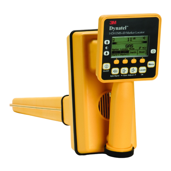
D. 3M™ Dynatel™ Electronic Marking System (EMS) Marker Locator 1420-iD Keypad and Display Definitions Access panel on bottom side of loca- tor under rubber cover [1] On/Off (Power): Turns unit on and off. [2] Speaker Volume Control: [2] Adjusts the volume of the locator (off, low, medium, and high). -
Page 7: Menu Displays
When the Menu [6] button is pressed, the Main Menu display appears. The function appears on the display above each soft key. Write Mode: System used to write information to 3M™ iD Markers Data/Template: Displays marker history and template creation/selection displays: a. - Page 8 Language – Toggles between English and alternate language. d. >>More - Advances to next menu display. e. <<Back - Returns to previous display. f. 3M™ Marker Type – enable and disable marker utility types. Self Test: Displays information about 3M Dynatel™ Electronic Marking System (EMS) Locator unit and performs a self check test.
-
Page 9: Locating 3M Electronic Markers And 3M Id Markers
Locator PC Tools software. The 3M™ Dynatel™ PC ™ ™ Tools software is available free of charge at www.3M.com/dynatel under the Software Updates section by clicking the Dynatel(TM) M-Series Locator PC Tools link.. Note: U-Model Locators ship with all marker types enabled (). U-model users can skip Section B. -
Page 10: Enabling/Disabling Marker And Path Frequencies
C. Enabling/Disabling 3M™ Marker and Path Frequencies Menu [6] + >>More [SK:4] + Setup [SK:6] + >>More [SK:6d] + Marker Type [SK:6f] Note: 3M Dynatel™ Electronic Marking System (EMS) Locator U-Model will default with all marker types enabled (✓) Step 1. Press the up/down arrows [SK] to highlight a utility to enable or disable. -
Page 11: Id Marker Depth
Step 1. Lower the tip of the locator to the ground over the targeted marker. Step 2. Press Depth [SK]. − The locator will examine the marker (Calculating, please wait...). − If the marker is a 3M iD Marker, the locator will display the depth of the marker, and its identification (serial) number. -
Page 12: Passive Electronic Marker (Non-Id) Depth
Step 6. Each memory location can be reviewed by pressing Mem Select [SK]. Step 7. Press Locate/OK [5] to return to Marker Locate Mode. G. Passive 3M™ Electronic Marker (Non-iD) Depth Step 1. Lower the tip of the locator to the ground over the targeted marker. -
Page 13: Creating/Editing Templates For 3M ™ Id Markers
In the User Template screen, the operator can create and modify templates for writing to iD markers. Note that the easiest way to create user templates is by using the 3M™ Dynatel™ PC Tool Kit software on a PC and then downloading them to a locator via the RS232 Serial Port [14] on the receiver and the provided RS232 cable or RS232-to-USB adapter cable. - Page 14 Step 7. Move the boxed cursor by pressing the left/ right arrows [SK] or up/down arrow [SK] to move the cursor up or down. Step 8. Press Select [SK] to enter the alphanumeric character. − Entry will appear at the top of the screen. Step 9.
-
Page 15: Editing Templates
Step 14. Populate as many fields as possible from the drop-down list of common (compressed) terms available to conserve marker memory space, or choose UserEdit if a term is not found to meet the user's requirements. Select term by pressing the up/down arrows [SK] and press Locate/OK [5]. -
Page 16: Writing 3M Id Markers
Cancel: Clears all modifications made to any unsaved template. 6. Writing 3M iD Markers ™ The Write Mode enables the user to write information into 3M iD markers. It is also ™ possible to edit the information to be written into an iD Marker. - Page 17 (scroll down by pressing the down arrow [SK]). Step 4. Enter user information that will be written to this marker. (See 6 A Modifying 3M™ Marker Data to be Written). Step 5. Verify that all information is correct.
-
Page 18: Modifying Marker Data To Be Written
PERMANENT. Choosing to permanently lock the marker data is irreversible. Once the data is locked it can not be overwritten. Assure that the data that is being written is correct before proceeding. A. Modifying 3M™ Marker Data to be Written To alter the information to be written into the marker Press Menu [6] + Write Mode [SK] Step 1. - Page 19 − [SK2] X-Type: Choose ‘Yes’ if writing to a Gen 2 marker and ‘No’ if writing to a Gen 1 marker. Gen 2 markers will have an “X” following the serial number that is printed on the attached tag. − [SK3] Marker: Select type of marker to be written by repeatedly pressing Marker [SK Toggle].
- Page 20 Step 8. If User Edit is selected, the following screen will appear. Step 9. Move the boxed cursor to the ‘back arrow’ and press Select [SK] to delete the entry to be modified. Step 10. Move the boxed cursor by pressing the left/ right arrows [SK] or the Up/ Down Arrow [SK] to move the cursor to the next row.
-
Page 21: Reading 3M Id Markers
The locator tip should be lowered to the ground to reach maximum read depth. If more than one 3M iD Marker of the same utility is detected, the locator will read the first marker and display the data from the marker. -
Page 22: Write History
B. Write History [SK] Menu [6] + Data Templat [SK:2] + Write History [SK:2b] • Select the 3M™ Marker data to be viewed by pressing the up/down arrows [SK]. • Press Write Details [SK] to view all data that was sent to the marker. -
Page 23: Sending 3M Id Marker Data To Gps (Capture-Transmit Mode / Mode 2)
(indicated by ‘iD’ in the model number) can be configured to send 3M iD Marker data directly to some GPS devices. When an iD marker is located and read, the information read from the iD marker, with feature and attribute data, is sent to the GPS device and is stamped with latitude, longitude and date/time data. - Page 24 Once downloaded to your PC, double click the file and an auto-installer will install the C Tool desktop software. Double click the 3M™ Dynatel™ PC Tool Kit icon on the desktop. Using the provided RS232 cable, or RS232-to-USB adapter cable, connect the Serial Port [14] on the locator to the PC and power the locator on.
-
Page 25: Locator Specifications
13. Locator Specifications: 3M™ Dynatel™ Electronic Marking System (EMS) Marker Locator 1420-iD Item Specification Frequencies / Markers Telephone, Power, Gas, Water, Waste Water, Communication (CATV), General Purpose Maximum Writing Range 3M iD Markers: Near-Surface 6 in (15 cm) Ball Marker... - Page 26 15. Locator Specifications: 3M™ Dynatel™ Electronic Marking System (EMS) Marker Locator 1420E-iD Item Specification Frequencies / Markers Telephone, Power, Gas, Water, Waste Water, Communication (CATV), General Purpose Maximum Writing Range 3M iD Markers: Near-Surface 15 cm (6 in) Ball Marker...
- Page 27 78-8130-6741-6 Rev G...
- Page 28 All statements, technical information and recommendations related to 3M Products are based on information believed to be reliable, but the accuracy or completeness is not guaranteed. Before using the 3M Product, you must evaluate it and determine if it is suitable for your intended application. Because conditions of Product use are outside of our control and vary widely you assume all risks and liability associated with such use.
Need help?
Do you have a question about the Dynatel 1420-iD and is the answer not in the manual?
Questions and answers