Table of Contents
Advertisement
Quick Links
Advertisement
Table of Contents

Related Manuals for Ingenico AXIUM RX7000


Summary of Contents for Ingenico AXIUM RX7000
- Page 1 AXIUM RX7000 User Guide...
-
Page 2: Table Of Contents
28-32, Boulevard de Grenelle, 75015 PARIS – FRANCE/ (T)+33(0)1 58 01 80 00 / (F)+33(0)1 58 01 91 Ingenico-SA au capital de 47 656 332 / 317 218 758 RCSNanterre Contents 1_Introduction ........................4 2_Unpacking ........................4 3_ Recommendations ....................... 5 3_1 Safety ........................ - Page 3 4_4 Setting the RX7000 on the standpole adaptor ........... 19 4_5 Fixing the stylus on RX7000 (optional) ............21 4_6 Fixing the pinshield on RX7000 (optional) ........... 22 5_Daily use ........................22 5_1 Card reading ..................... 22 5_1_1 Swiping a card ..................22 5_1_2 Inserting a smart card ................
-
Page 4: 1_Introduction
1_Introduction Thank you for choosing an Ingenico payment terminal. We recommend you to read carefully this user guide: it gives you the necessary information about safety precautions, unpacking, installation and maintenance of your terminal. This symbol indicates an important Warning. -
Page 5: 3_ Recommendations
The user guide 3_ Recommendations 3_1 Safety Power on/Power down - Emergency stop To power on or power down the terminal, connect or disconnect the power supply from the electric outlet. CAUTION Only use the power supply AC/DC provided with RX7000. -
Page 6: 3_2 Security Of Your Terminal (Tampering Attempt Detection)
Explosion areas Certain regulations restrict the use of radio equipment in chemical plants, fuel depots and any site where blasting is carried out. You are urged to comply with these regulations. The terminal shall be protected by a specially fitted and certified cover enabling use in proximity to a fuel pump. - Page 7 the chip card reader or any other part of your terminal. Such checks would provide warning of any unauthorised modifications to your terminal, and other suspicious behaviour of individuals that have access to your terminal. Your terminal detects any “tampered state”. In this state the terminal will repeatedly flash the message”...
-
Page 8: 3_3 Main Characteristics
CAUTION Positioning of the RX7000 on check stand must be in such a way to make cardholder PIN (Personal Identification Number) spying infeasible. Installing device on an adjustable stand must be in such a way that consumers can swivel the terminal sideways and/ or tilt it forwards/backwards to a position that makes visual observation of the PIN-entry process difficult. -
Page 9: 3_3_2 Power Characteristics
-20°C, +70°C Max relative humidity 90% at +55°C 3_3_2 Power characteristics RX7000 works at voltages between 8VDC and 14VDC. The following power adapters are recommended Manufacturer Model Technical data Ingenico PSC16A-080L6 Input: 100-240Vac,50-60Hz,0.5A; Output: 8Vdc,2A,DC JACK Tmax:40℃ PHIHONG TECHNOLOGY AM24W-080B Input: CO., LTD. -
Page 10: 3_3_3 Terminal Connectivity
1.0A; Output: 8Vdc,3A Tmax:45℃ If additional adapters are used, please check that the poweroutput is less than 100W. 3_3_3 Terminal Connectivity USB host High speed USB Host in the single connector USB device High speed USB Device in the single connector Ethernet 10/100 Base T Ethernet is available on the... -
Page 11: 3_3_5 Bluetooth
Frequency band 5 GHz 5180 MHz to 5240 MHz; 5260 MHz to 5320 MHz; 5500 MHz to 5700 MHz; 5745 MHz to 5825 MHz Type of modulation 802.11b : CCK 802.11 g/n : OFDM /64-QAM、16-QAM、 QPSK、BPSK 802.11a : OFDM /64-QAM 、 16-QAM 、 QPSK、BPSK Number of channels 2.4GHz:Ch1 ~ Ch11... -
Page 12: 3_4 Functional Description
Number of channels 79 channels for classic、40 channels for Bluetooth instructions: Enter “setting”, and enter the password“350000” Select “Connected devices” and select “Pair new device”. Choose one of available devices to connect. 3_4 Functional description... -
Page 13: 4_Installation & Connections
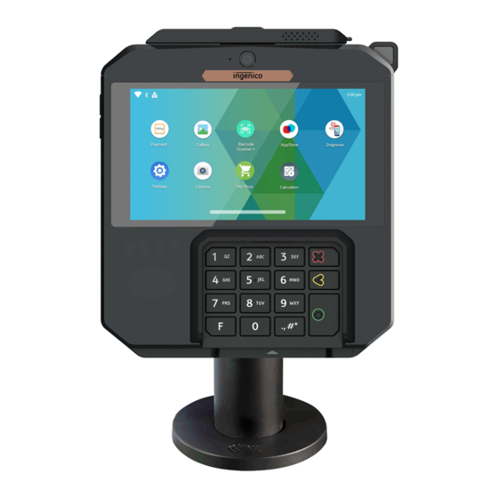
1.Stylus(Optional)2. Front Camera3. Volume key 4. 5.5 inchtouch screen 5. 3.5mm AudioJack6. Contactless Reader7. Keypad8. SmartcardReader 9. MagneticStripeReader 10. Shimmer detection(Optional)11. Multipoint connector 12. Speaker 13. StandpoleAdaptor Pattern 14. Rear Camera(optional) 15. Micro SDCard 16. SAM Card1 &2 4_Installation & Connections 4_1 Positionning the terminals Place the terminal with an easy access to an electrical outlet. -
Page 14: 4_2 Inserting Sam (Secure Access Module) And Micro Sd
made for indoor use. The RX7000 device may be mounted on a flat surface, wall, or customer stand. CAUTION Do not place the RX7000 device on a PC monitor, adjacent to an electronically active security tag deactivation system, or near other sources of magnetic fields. The RX7000 device must be at least 30 centimeters (12 inches) away from an ... - Page 15 Unscrew the cover and remove it Access to SAM and Micro SD is now possible. Insert the SAM Card into the slot marked (1), (2) . Take care to ensure that the SAM Card is inserted in the correct manner. The cut corner must be positioned as indicated in the slot.
-
Page 16: 4_3 Connecting The Terminal To The Host
WARNING The main port at the back must not be used to connect an HDMI video cable. Only connect cables provided by Ingenico. Note : 2 screws can be added (M2.5 x 8) to hold more firmly the cable. The terminal can be connected to the host by several ways, with optional cables :... - Page 17 High speed USB device High speed USB host Ethernet RS232 Most of the cables used with iSC and iPP ranges are compatible with the RX7000. We advise to check with your reseller their compatibility if you plan to replace a Lane/7000 by a RX7000.
- Page 18 USB connector USB powered 12V cable (optional) References: 296116381AE (length 4.9m) Connector for terminal Special USB shielded cable Ethernet cable (optional) Reference : 296248646(length 4m) Connector for terminal Power supply unit...
-
Page 19: 4_4 Setting The Rx7000 On The Standpole Adaptor
4_4 Setting the RX7000 on the standpole adaptor Install the terminal on a flat surface is not possible on the RX7000 as is. It is designed to be fitted on a standpole adaptor. A specific pattern by Ingenico has been developed to fit the RX7000. - Page 20 To fit the RX7000 to the stand pole adaptor,it only requires to slide down the RX7000 until a click sound: The RX7000 is now ready to use :...
-
Page 21: 4_5 Fixing The Stylus On Rx7000 (Optional
4_5 Fixing the stylus on RX7000 (optional) Usetheglueofholdertofixitonthe RX7000. Glue There is a magnet in thestylus,anditcanbefixedontheholder. -
Page 22: 4_6 Fixing The Pinshield On Rx7000 (Optional
4_6 Fixing the pinshield on RX7000 (optional) Use the glue of pinshield to fix it on the RX7000 as follows: Glue a rea Glue a rea Glue area Glue 5_Daily use 5_1 Card reading 5_1_1 Swiping a card Insert the card manually in the reader, magnetic stripe facing the main body of the ... -
Page 23: 5_1_2 Inserting A Smart Card
5_1_2 Inserting a smart card Chip cards should be inserted into your terminal as illustrated with the chip facing up and into the card reader. -
Page 24: 5_1_3 Reading A Contactless Card
5_1_3 Reading a contactless card Bring the card to the active zone above the contactless logo (at about 1cm). Keep the card close to the contactless logo during the transaction. Your contactless terminal provides four contactless status lights located above the contactless logo. -
Page 25: 5_2 Signature Capture
successful when all four status lights are lit and a confirmation tone can be heard. CAUTION Do not stick any label onto the contactless active zone. It can decrease seriously contactless efficiency. CAUTION Avoid metallic parts around the contactless area. 5_2 Signature capture The signature capture is done with a stylus and a capacitive touchscreen 5_3 Audio... -
Page 26: 5_4 Reboot Rx7000
is no more sound from the speaker. The audio jack is located ontheleftoftheterminal. This option is not designed to play music, but to facilitate the use by blind people. The jack is 3.5mm and the volume key is only used to control the volume of headset. ... -
Page 27: 5_5_2 Rear Camera(Optional)
5_5_2 Rear camera(optional) Rear camera is used to scanning. 5_6 ShimmerSkimmer (optional) The shimmer skimmer is used to detect the items which entries the key area and alert users. -
Page 28: 6_Maintenance
6_Maintenance CAUTION Before making any operations of maintenance in the terminal, make sure that the power supply is disconnected. 6_1 Cleaning of the terminal First of all, unplug all the wires from the terminal. Good rules for proper cleaning of the terminal are : Do not clean the electrical connections. -
Page 29: 6_2 Transport And Storage
6_2 Transport and storage Use the original packaging for storage or returning the unit. Disconnect all cables from the terminal during the transport. 7_Standard FCC Warning This device complies with part 15 of the FCC Rules. Operation is subject to the following two conditions: (1) This device may not cause harmful interference, and (2) this device must accept any interference received, including interference that may... - Page 30 This transmitter must not be co-located or operating in conjunction with any other antenna or transmitter. This equnpment should be installed and operated with minimum distance 20cm between the radiator &you body. ISEDC WARNING This device complies with ISEDC licence--exempt RSS standard (s).Operation is subject to the following two conditions: (1) this device may not cause interference,and (2) this device mustaccept any interference,including interference that may cause undesired operation of the device.
- Page 31 operating in conjunction with any other antenna or transmitter. Le rayonnement de la classe b repecte ISED fixaient un environnement non contrôlés. Installation et mise en œuvre de ce matériel devrait avec échangeur distance minimale entre 20cm tonon corps.Lanceurs ou ne peuvent pas coexister cette antenne ou capteurs avec d’autres.
- Page 32 INGENICO. If such permission is granted, it will be subject to the condition that the recipient ensures that any other recipient of this document, or information contained therein, is held responsible to INGENICO for the confidentiality of that information.
- Page 33 All trademarks used in this document remain the property of their rightful owners.” www.ingenico.com 28-32, Boulevard de Grenelle, 75015 PARIS – FRANCE/ (T)+33(0)1 58 01 80 00 / (F)+33(0)1 58 01 91 Ingenico-SA au capital de 47 656 332 / 317 218 758 RCSNanterre...
Need help?
Do you have a question about the AXIUM RX7000 and is the answer not in the manual?
Questions and answers