Advertisement
Quick Links
Advertisement

Related Manuals for Roger PR302


Summary of Contents for Roger PR302
- Page 1 PR302 v2.1 Rev. G © 2016 ROGER sp. z o.o. sp.k. All rights reserved. This document is subject to the Terms of Use in their current version published at the www.roger.pl website of the Roger sp. z o.o. sp.k. company (hereinafter referred to as ROGER).
-
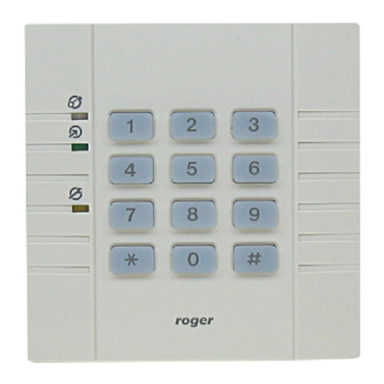
Page 2: Installation
Installation The PR302 can be installed in indoor location only. All electrical connections must be made before power supply will be applied. Factory new unit is configured for address ID=00 and has programmed MASTER PIN (1234) and MASTER card (delivered with the new device). The MASTER card/PIN can be used for initial testing of the controller - the single use of MASTER card/PIN activates momentarily REL1 output (for approx. - Page 3 PR302 Installation Guide Inputs The PR302 offers three programmable inputs (IN1, IN2 and IN3). All of them have the same electrical structure and can be configured as NO or NC line. Each input is internally biased to supply plus (+12V) through 15kΩ resistor what makes that supply plus is observed on the free (not connected) input.
- Page 4 Access terminals (readers) and expanders (e.g. XM-2-BRD, XM-8-BRD) can be connected to controller through CLK and DTA lines. Controller can operate either with Roger access terminals (using RACS data output format) or with any other type of readers which are equipped with Wiegand or Magstripe interfaces.
-
Page 5: Memory Reset
2020-10-19 PR302 Installation Guide Memory Reset Memory Reset procedure enables erasing of current settings and returning to default factory settings. Full procedure also allows to program new MASTER card/PIN as well as new address of the controller. After Memory Reset procedure, the controller automatically enters normal working mode. -
Page 6: Firmware Upgrade
(every new firmware version is published on www.roger.pl). Our customers are advised to register at web site so Roger will let inform when new versions are ready for download. The new firmware can be downloaded without removal of the controller from live installation. - Page 7 2020-10-19 PR302 Installation Guide Technical specification Supply voltage Nominal 12VDC, min./max. range 10-15VDC Current consumption average 80 mA Anti-sabotage Isolated contact, NC type, 24V/50mA rated, IP67 Reading distance UP to 12 cm for ISO card (depends on card type) Cards...
- Page 8 2020-10-19 PR302 Installation Guide 8/10...
- Page 9 2020-10-19 PR302 Installation Guide 9/10...
- Page 10 Weight of the equipment is specified in the document. Contact: Roger sp. z o.o. sp.k. 82-400 Sztum Gościszewo 59 Tel.: +48 55 272 0132 Fax: +48 55 272 0133 Tech.
Need help?
Do you have a question about the PR302 and is the answer not in the manual?
Questions and answers