
Subscribe to Our Youtube Channel
Related Manuals for Afag SE-24


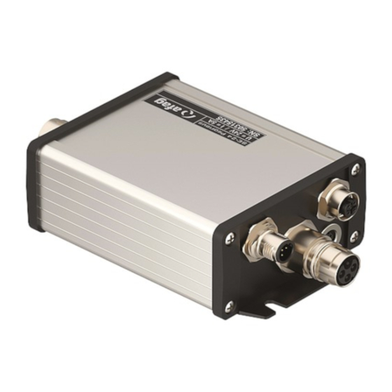
Summary of Contents for Afag SE-24
- Page 1 Servo Controller SE-24 Operating Instructions ▪ Operating manual © Copyright by Afag Automation AG...
- Page 2 SE-24 I/O 50315434 SE-24 Profibus 50315435 SE-24 EtherCAT 50315436 SE-24 CANopen 50315437 Accessories Order No. Programming cable SE-24, 3m 50315431 SE-24 Stick 50315432 I/O cable SE-24, 5m 50312913 Power cable SE-24/SE-48, 5m 50118124 Brake release switch SE-24 50315438 Assembly and initial start-up may be carried out by qualified personnel only and according to these operating instructions.
- Page 3 Disregard of this information can result in damage to property or light to medium personal injuries. NOTE Indicates general notes, useful operator tips and operating recommendations which don't affect safety and health of the personnel. ◼ ◼ ◼ Operating instructions EN SE-24 01.06.2022 V1.5 3–66...
-
Page 4: Table Of Contents
Protection during handling and installation ..........20 Product description .................. 21 Basic information ..................21 Field of application and proper use ............22 SE-24 performance features ..............23 Technical data ..................24 Ambient conditions and qualification ............24 Dimensions and weight ................24 Power data .................... - Page 5 Encoder connection [X6] ................43 7.2.3 Reference sensor connection [X7] ............44 Electrical installation of the SE-24 in the system ........45 Connection to the power supply and the controller ........45 Emergency off / Emergency stop ............. 46 Functional description ................49 Basic functions..................
- Page 6 Figure 15: View of the connection [X6] ....................43 Figure 16: View of the connection [X7] ....................44 Figure 17: Example of a circuit diagram of the SE-24 I/O ..............47 Figure 18: Example of a circuit diagram of the SE-24 fieldbus ............. 48 Figure 19: Position mode........................
-
Page 7: Declaration Of Incorporation
Schweiz Description and identification of the partly complete machinery: Product Servo controller SE-24 Types SE-24 I/O / SE-24 Profibus / SE-24 EtherCAT / SE-24 CANopen The designated products are in conformance with the regulations of the following European Directives. Number... -
Page 8: General
Description of the technical data and the functions of the device as well as notes on the plug assignment, installation and operation of the SE- 24 servo controller. It is meant for persons who want to get familiar with the SE-24 servo controller. CAUTION... - Page 9 Description of the I/O control of the SE-24 servo controller. ▪ ☐ SE-24 Profibus Manual Description of the fieldbus control of the SE-24 servo controller under PROFIBUS-DP. ☐ ▪ SE-24 programming example Siemens S7 V5.5 Description to the programming example for Siemens S7 V5.5.
-
Page 10: Safety Instructions For Electrical Drives And Controllers
NOTE In the case of damage owing to disregard of the warning notices in this operating manual Afag will not accept any liability. If the documentation in the language that has been supplied is not easily understood, please ask and inform the supplier. - Page 11 Opening of the servo controller by the owner/operator is not permitted for reasons of safety and warranty. NOTE The precondition for trouble-free working of the servo controller is a technically sound planning. ◼ ◼ ◼ Operating instructions EN SE-24 01.06.2022 V1.5 11–66...
-
Page 12: Dangers From Improper Use
The surfaces of the machine housing may be hot. Danger of injury! Danger of burns! CAUTION Movements that cause danger! Danger to life, serious bodily injury or damage to property from unintentional movements of the motors! 12 – 66 ◼ ◼ ◼ Operating instructions EN SE-24 01.06.2022 V1.5... -
Page 13: Safety Instructions
RC-elements or diodes. NOTE The safety specifications and regulations of the country in which the device is to be used must be followed. ◼ ◼ ◼ Operating instructions EN SE-24 01.06.2022 V1.5 13–66... - Page 14 (e.g. DIN, VDE, EN, IEC or other national or international specifications) must be observed. Disregard can result in death, bodily injuries or considerable damage to property. 14 – 66 ◼ ◼ ◼ Operating instructions EN SE-24 01.06.2022 V1.5...
-
Page 15: Safety Instructions For Installation And Maintenance
CAUTION The operation, maintenance and/or repairs to the servo controller may only be carried out by personnel who are trained and qualified to work on electrical devices. ◼ ◼ ◼ Operating instructions EN SE-24 01.06.2022 V1.5 15–66... - Page 16 (24 V) is switched off. NOTE The intermediate circuit or the mains voltage must always be switched off before the 24V voltage supply of the controller is switched off. 16 – 66 ◼ ◼ ◼ Operating instructions EN SE-24 01.06.2022 V1.5...
- Page 17 CAUTION The servo controller can reach high temperatures and may cause heavy burns when touched. ◼ ◼ ◼ Operating instructions EN SE-24 01.06.2022 V1.5 17–66...
-
Page 18: Protection Through Protective Low Voltage (Pelv) Against Electrical Shocks
▪ error in the measuring and signal transmitters ▪ faulty or non-EMC conformant components ▪ error in the software in the higher-level control system 18 – 66 ◼ ◼ ◼ Operating instructions EN SE-24 01.06.2022 V1.5... -
Page 19: Protection Against Touching Hot Parts
▪ Before access, allow the devices to cool for 10 minutes after switching off. ▪ If hot parts of the equipment, like machine housings, in which radiators and resistors are located are touched, burns may result! ◼ ◼ ◼ Operating instructions EN SE-24 01.06.2022 V1.5 19–66... -
Page 20: Protection During Handling And Installation
▪ Do not stay under suspended loads. ▪ Immediately wipe off any liquids which have escaped since there is a danger of slipping. 20 – 66 ◼ ◼ ◼ Operating instructions EN SE-24 01.06.2022 V1.5... -
Page 21: Product Description
4 Product description 4.1 Basic information The devices of the SE-24 series are ultra compact four quadrant controllers in the protection class IP65 which can be installed outside the switch cabinet. They are suitable for brushless motors and motors with brushes and were especially designed for the drive of Afag handling components. -
Page 22: Field Of Application And Proper Use
The SE-24 servo controller is designed for the decentralised control and regulation of three phase permanent magnet synchronous machines. The SE-24 servo controller is supplied with a 24 VDC (logic), and 24 VDC (intermediate circuit) protective low voltage via a mains adapter. At the motor connection, the synchronous machine is supplied with a pulse width modulated symmetrical 3 phase rotating field with variable frequency, current and voltage. -
Page 23: Performance Features
▪ Full integration of all components for the controller and power section including a USB interface (SE-24 Stick) for the PC communication. ▪ Integrated rotary encoder analysis for the incremental encoder with or without commutation signals. -
Page 24: Technical Data
EN61000-6-2 Immunity for industrial environments EN61000-6-4 Emission for industrial environments 5.2 Dimensions and weight Parameters Values Dimensions (H*W*D) 47 x 87 x 165 mm (without mating plug connector) Weight approx. 490 g 24 – 66 ◼ ◼ ◼ Operating instructions EN SE-24 01.06.2022 V1.5... -
Page 25: Power Data
=24V, T =40°C) Rated output current =24V, T =40°C) Protective devices Parameters Values Overvoltage power-off Undervoltage power-off Excess temperature cut-out 5.5 Motor temperature monitoring Parameters Values Analog sensor PTC 111-K13-140° Reissmann ◼ ◼ ◼ Operating instructions EN SE-24 01.06.2022 V1.5 25–66... -
Page 26: Emitter Evaluation And Analog Input [X6]
Supply voltage for Hall sensors and encoder Output voltage 5 V +/-5 % max. load 200 mA Analog input Type Single ended 0…10 V Measuring range Resolution 10 bit Input impedance ca. 20 kOhm 26 – 66 ◼ ◼ ◼ Operating instructions EN SE-24 01.06.2022 V1.5... -
Page 27: Parameterization Interface (Can) [X4]
9 V…30 V Input voltage, high IN high Input voltage, high max. typ. 5.3 mA (@ U =30V) Digital outputs Type plus switching max. output current 0.7 A Short-circuit proof ◼ ◼ ◼ Operating instructions EN SE-24 01.06.2022 V1.5 27–66... -
Page 28: Mechanical Installation
6 Mechanical installation 6.1 Important information ▪ For installation of the SE-24 the cut-outs at the end plates should be used as fastening points. Screw size: M5 ▪ Keep a clearance of 100 mm above the device in order to ensure adequate ventilation of the SE-24. -
Page 29: Electrical Connection
Figure 3: View of the connections on the input side (IN), I/O type (left) and fieldbus (right) Plug Designation Performance and logic supply I/O interface X2a, X2b, X2d Fieldbus In (M12) X3a, X3b, X3d Fieldbus Out (M12) Programming interface ◼ ◼ ◼ Operating instructions EN SE-24 01.06.2022 V1.5 29–66... -
Page 30: Power Supply Connection [X1]
7.1.1.1 Type on device [X1] ▪ Intercontec, 4 pole M17; flush-type power plug; BEGA894MR0900153A000 7.1.1.2 Mating plug [X1] ▪ Power cable SE-24/SE-48, 5 m, Afag no. 50118124 7.1.1.3 Pin assignment [X1] Designation Specification 0 Volt Common ground potential for the 24 V power supply and the 24 V control supply Conductor cross-section at least 1.5mm... -
Page 31: Input And Output Connections [X2]
7.1.2.1 Type on device [X2] ▪ Phoenix Contact: 12 pole sensor-/actuator flush-type plug, SACC-DSI-M12MS-12CON-M16/0,5 Phoenix Contact No.1419700 7.1.2.2 Mating plug [X2] ▪ I/O cable SE-24, 5m, Afag No. 50312913 7.1.2.3 Pin assignment of the I/O cable Designation Colour assignment drive_enable/fault_reset brown... -
Page 32: Profibus Connection
7.1.3 Profibus connection The Profibus connection on the SE-24 servo controller is carried out as a 5 pole M12 plug or socket (b-coded) according to EN 50170. 7.1.3.1 Profibus IN [X2b] X2b, Profibus IN Flush-type plug, 5 pole M12, b-coded... -
Page 33: Bus Cable For Profibus
Bus system cable, PROFIBUS, 2 pole, PUR halogen-free, violet RAL 4001, shielded, straight M12-SPEEDCON plug, b-coded, on straight M12-SPEEDCON socket, b- coded Phoenix Contact Profibus cable PROFIBUS cable Order No. Length in m 1518106 1518119 1518122 1518135 1518148 1518151 1518164 ◼ ◼ ◼ Operating instructions EN SE-24 01.06.2022 V1.5 33–66... -
Page 34: Termination And Bus Terminating Resistors
The termination is done at the beginning and at the end of a bus segment. Due to the high protection class the PROFIBUS module of the SE-24 servo controller has no integrated terminating resistors. -
Page 35: Ethercat Connection
7.1.6 EtherCAT connection The EtherCAT is connected to the SE-24 servo controller via two d-coded 5 pole M12 sockets. 7.1.6.1 EtherCAT IN [X2d] X2d, EtherCAT IN Flush-type socket, 5 pole M12, d-coded Phoenix: 1419616 SACC-DSI-M12FSD-4CON-M16/0,5 Designation Specification Transmission data +... -
Page 36: Bus Cable For Ethercat
EtherCAT cable M12 plug, straight, d-coded, 4 pole M12 plug, straight, d-coded, 4 pole Beckhoff EtherCAT cable EtherCAT cable Order No. Length in m ZK1090-6161-0005 ZK1090-6161-0020 ZK1090-6161-0025 ZK1090-6161-0050 ZK1090-6161-0100 36 – 66 ◼ ◼ ◼ Operating instructions EN SE-24 01.06.2022 V1.5... -
Page 37: Canopen Connection
7.1.8 CANopen connection The CANopen connection on the SE-24 servo controller is carried out as a 5 pole M12 plug or socket (a-coded). 7.1.8.1 CANopen IN [X2a] X2a, CANopen IN Flush-type plug, 5 pole M12, a-coded Phoenix: 1419645 SACC-DSI-M12MS-5CON-M16/0,5 Designation... -
Page 38: Bus Cable For Canopen
Bus system cable, CANopen/DeviceNet, 5 pole, PUR halogen-free, violet RAL 4001, shielded, straight M12-SPEEDCON plug, a-coded, on straight M12-SPEEDCON socket, a-coded Phoenix Contact CANopen cables CANopen-Kabel Order No. Length in m 1518258 1518261 1518274 1518287 1518290 1518300 1518313 38 – 66 ◼ ◼ ◼ Operating instructions EN SE-24 01.06.2022 V1.5... -
Page 39: Termination And Bus Terminating Resistors
The termination is done at the beginning and at the end of a bus segment. Due to the high protection class the CAN module of the SE-24 servo controller has no integrated terminating resistors. -
Page 40: Parameterization Connection [X4]
7.1.11 Parameterization connection [X4] The parameterization connection on the SE-24 servo controller is carried out as a 4 pole M8 socket. 7.1.11.1 Parameterization X4, parameterization connection connection [X4] Female socket, 4 pole M8 Binder: 09-0412-00-04 Subminiature connector, series 712 Designation... -
Page 41: Connections On The Output Side (Out)
7.2 Connections on the output side (OUT) Figure 13: View of the connections on the output side (OUT), all types Plug Designation Motor connection Transmitter connection Reference sensor connection ◼ ◼ ◼ Operating instructions EN SE-24 01.06.2022 V1.5 41–66... -
Page 42: Motor Connection [X5]
Intercontec, 7 pole, M17 flush-type power socket; BEGA 861 FR 01 00 152A 000 7.2.1.2 Mating plug [X5] ▪ Afag cable depending on the module to be connected ▪ or Intercontec plug, 7 pole, M17 power cable plug; BSTA 878 MR 08 86 001A 000 7.2.1.3 Pin assignment [X5]... -
Page 43: Encoder Connection [X6]
▪ Binder, miniature circular connector 14 pole, series 423, 09-0454-80-14 7.2.2.2 Mating plug [X6] ▪ Afag cable depending on the module to be connected ▪ or Binder miniature circular connector, 14 pole, series 423 7.2.2.3 Encoder pin assignment [X6] Pin No. -
Page 44: Reference Sensor Connection [X7]
7.2.3 Reference sensor connection [X7] The reference sensor connection on the SE-24 servo controller is carried out as a 3 pole M8 socket. 7.2.3.1 Reference sensor connection X7, reference sensor connection [X7] Flush-type socket, 3 pole M8 Phoenix: 1453449 SACC-DSI-M8FS-3CON-M12/0,5... -
Page 45: Electrical Installation Of The Se-24 In The System
A common reference potential is used (GND). Connection to a higher level control system (PLC) is carried out - dependent on the SE-24 model – via digital inputs and outputs or a fieldbus system (Profibus DP, EtherCAT, CANopen). The SE-24 servo controller must be completely connected before the voltage supply for the power and control electronics are turned on. -
Page 46: Emergency Off / Emergency Stop
SE-24 “drive_enable/fault_res” signal. In case of an error (Emergency Off, Emergency Stop) the power supply and the controller release are switched off. With the SE-24 I/O the “drive_enable/fault_res” signal should also be carried out via the ECS. The choice of a suitable ECS is dependent on the concrete application. In the simplest case, an ECS is not required. -
Page 47: Figure 17: Example Of A Circuit Diagram Of The Se-24 I/O
Figure 17: Example of a circuit diagram of the SE-24 I/O ◼ ◼ ◼ Operating instructions EN SE-24 01.06.2022 V1.5 47–66... -
Page 48: Figure 18: Example Of A Circuit Diagram Of The Se-24 Fieldbus
Figure 18: Example of a circuit diagram of the SE-24 fieldbus 48 – 66 ◼ ◼ ◼ Operating instructions EN SE-24 01.06.2022 V1.5... -
Page 49: Functional Description
9 Functional description 9.1 Basic functions With the SE-24 servo controller two different operating modes are available which can also be switched over during operation. Move to position – check moment (current) Position mode: Move to moment (current) – check position Current mode: 9.1.1 Position mode... -
Page 50: Figure 19: Position Mode
X = position_value (actual position) Y = target_position (target position) Y = target_position (abortion position) Current = maximum current (from parameterization) Current = target_current Figure 19: Position mode Figure 20: Current mode 50 – 66 ◼ ◼ ◼ Operating instructions EN SE-24 01.06.2022 V1.5... -
Page 51: Dynamic Current Limitation
(CURR_DynLimitCont). The longer the motor current was under the continuous current Ic (CURR_DynLimitCont) and the lower it was, that higher would be the allowed temporary motor current, meanwhile the peak current Ip (CURR_DynLimitPeak) keeps limited. Figure 21: Dynamic current limitation ◼ ◼ ◼ Operating instructions EN SE-24 01.06.2022 V1.5 51–66... -
Page 52: I/O Signal Diagram
9.3 SE-24 I/O signal diagram ready drive_enable_ok rev_valid move_ok drive_enable_fault_res start_stop_rev start_stop_move pos_nr_bit0 pos_nr_bit1 Restart Search start of commutation pos. Commutation position found Start reference run End reference run Selection motion block 1 (position mode) Start in positioning mode Position window reached... -
Page 53: Fieldbus Signal Diagram
9.4 SE-24 fieldbus signal diagram ready drive_enable_ok rev_valid move_ok drive_enable_fault_res start_stop_rev start_stop_move mode Restart Search start of commutation pos. Commutation position found Start reference run End reference run Start in positioning mode Position window reached Start in current mode Current window reached... -
Page 54: Error Messages/Fault Diagnosis Chart
The errors which occurred are shown as numbers. These can be read directly on the servo controller with the “afagTools” parameterization program. With the Bus models of the SE-24 the error numbers can also be read in the “error_no” object. Object name... -
Page 55: Table 1: Error Register
Saved parameters are defect (wrong CRC32 checksum) 0x6320 -322 0xFEBE ERR_Par_CannotSet_AxIsMoving Parameter cannot be written because a movement is carried out -325 0xFEBB ERR_Par_CannotSet_PosModeIsNotEnabl Parameter cannot be written because positioning mode is not active ◼ ◼ ◼ Operating instructions EN SE-24 01.06.2022 V1.5 55–66... - Page 56 SG-50 for example. The calibration will only be executed automatically at the first time when the enable will be set after a restart. Device errors 56 – 66 ◼ ◼ ◼ Operating instructions EN SE-24 01.06.2022 V1.5...
- Page 57 Encoder error Regv errors -3010 0xF43E ERR_Blockage The motor was blocked Regp errors -4000 0xF060 ERR_Regp_FollowingError Permissible servo lag was exceeded 0x8611 Homing errors -4200 0xF43E ERR_Home_UnknownMethod Unknown referencing method ◼ ◼ ◼ Operating instructions EN SE-24 01.06.2022 V1.5 57–66...
- Page 58 It is possible that this fault number has been assigned additional monitoring functions in the course of firmware updates or in the case of customer specific firmware versions. 58 – 66 ◼ ◼ ◼ Operating instructions EN SE-24 01.06.2022 V1.5...
-
Page 59: Instructions For Safe And Emc Compatible Installation
▪ Motor ▪ Electromechanics ▪ Realisation and type of wiring ▪ Higher level controller NOTE The SE-24 servo controller was checked according to the applicable EMC directives EN61000-6-2 Immunity for industrial environments EN61000-6-4 Emission for industrial environments ◼ ◼ ◼... -
Page 60: Emc Categories: First And Second Environments
11.3 EMC categories: first and second environments The SE-24 servo controller, when correctly installed and connected, complies with the regulations of the corresponding product norms EN 61000-6-2 and EN-61000-6-4. In these norms, reference is no longer made to “limiting value classes”, but to so called environments. -
Page 61: Connection Between Se-24 And Mains Adapter
PE as well as between GND and ▪ Ensure a “good” PE connection between the mains adapter and the SE-24. It is important to have a good refeed of the high frequency leakage current, generated by the chopper in the SE-24 in combination with the winding capacity between the motor phase and the PE in the motor. -
Page 62: Accessories
The SE-24 Stick is needed together with the Programming cable SE-24 if the “afagTools” parameterization program is used to access the controller. The SE-24 Stick is the gateway from USB to CANopen and can be used for all types of the SE-24 servo controller. -
Page 63: I/O Cable Se-24, 5M (50312913)
12.3 I/O cable SE-24, 5m (50312913) The SE-24 I/O cable is the connection between the SE-24 servo controller and a higher level control system (PLC, PC) for transmission of digital inputs and outputs and can only be used for the type SE-24 I/O. -
Page 64: Brake Release Switch Se-24 (50315438)
12.5 Brake release switch SE-24 (50315438) The Brake release switch SE-24 is needed when a motor with parking brake is connected to the SE-24 servo controller and the brake is to be released manually. The Brake release switch SE-24 is inserted in the parameterization connection [X4] and can be used for all types of the SE-24 servo controller. - Page 65 ◼ ◼ ◼ Operating instructions EN SE-24 01.06.2022 V1.5 65–66...
- Page 66 Afag Automation AG Luzernstrasse 32 CH-6144 Zell Switzerland Tel.: +41 (0)62 959 86 86 Fax.: +41 (0)62 959 87 87 e-mail: sales@afag.com Internet: www.afag.com...
Need help?
Do you have a question about the SE-24 and is the answer not in the manual?
Questions and answers