Table of Contents

Related Manuals for Afag 50371863


Summary of Contents for Afag 50371863
- Page 1 Operating Instructions Controller Smart Box Translation of the Original Operating Instructions EN Controller Smart Box (230 V/50 Hz) Order no: 50371863 ◼ Operating instructions EN ◼ Smart Box ◼ 17.02.2024 ◼ Version 3.0 1-32...
- Page 2 Your Afag team © Subject to modifications The controllers have been designed by Afag GmbH according to the state of the art. Due to the constant technical development and improvement of our products, we reserve the right to make technical changes at any time.
-
Page 3: Table Of Contents
Table of contents Table of contents General ........................5 Contents and purpose of this manual ............5 Explanation of symbols................. 5 Additional symbols ..................6 Warranty ....................... 7 Liability ......................7 Safety instructions ....................8 General ......................8 Intended use ....................8 Foreseeable misuse .................. - Page 4 Table of contents Safety instructions ..................20 General notes on settings ................20 Menu control and displays ................20 Settings ....................... 22 7.4.1 Setting options ..................22 7.4.2 System release - Code C 003 .............. 23 7.4.3 Hopper conveyor level control - Code C 004 ........24 7.4.4 Bowl feeder status line, air jet - Code C 007 ........
-
Page 5: General
General General Contents and purpose of this manual These assembly instructions contain essential information on assembly, commissioning, functioning and maintenance of the controller to ensure safe and efficient handling and operation. Consistent compliance with these operating instructions will ensure: ▪ permanent operational reliability of the controllers, ▪... -
Page 6: Additional Symbols
General This note contains important additional information as well as useful tips for safe, efficient, and trouble-free operation of the controllers. Further warning signs: Where applicable, the following standardized symbols are used in this manual to point out the various potential health risks. Warning - Dangerous electrical voltage. -
Page 7: Warranty
General Warranty The warranty terms for Afag feeding components and handling systems are the following: ▪ 24 months from initial operation and up to a maximum of 27 months from delivery. ▪ Wear parts are excluded from the warranty (The customer is entitled to a product free of defects. -
Page 8: Safety Instructions
Safety instructions Safety instructions General This chapter provides an overview of all important safety aspects to ensure safe and proper use of the controllers and optimal protection of personnel. Safe handling and trouble-free operation of the controller requires knowledge of the basic safety regulations. -
Page 9: Obligations Of The Operator And The Personnel
Safety instructions Obligations of the operator and the personnel 2.4.1 Follow these instructions A basic prerequisite for safe and proper handling of the controllers is a good knowledge of the basic safety instructions. This manual, particularly the safety instructions contained therein, must be observed by all persons working with the controllers. -
Page 10: Personnel Requirements
Safety instructions Personnel requirements 2.5.1 Personnel qualification The activities described in the operating instructions require specific requisites at the level of professional qualifications of the personnel. Personnel not having the required qualification will not be able to assess the risks that may arise from the use of the controllers thus exposing himself and others to the risk of severe injury. -
Page 11: Changes And Modifications
No changes may be made to the controller which have not been described in these operating instructions or approved in writing by Afag. Afag accepts no liability for unauthorized changes or improper assembly, installation, commissioning, maintenance, or repair work. General hazards / residual risks Observe the safety instructions in this chapter and in the other sections of this manual to avoid damage to property and dangerous situations for the personnel. -
Page 12: Technical Data
Technical data Technical data Dimensional drawing of controller Smart Box Fig. 1 Dimensional drawing of controller Smart Box 12 – 32 Operating instructions EN ◼ Smart Box ◼ 17.02.2024 ◼ Version 3.0... -
Page 13: 3.2 Technical Data
Technical data 3.2 Technical data Accessories Type Designation Order Number for 1 IRG 50450178 for 2 IRG 50450179 Support for 1 IRG extended 50450145 for 2 IRG extended 50450147 Connection cable Type Designation Order Number Connection cable 0.3 m 15131112 Connection cable 0.6 m 15057366 M8, 3pin... -
Page 14: Transport And Storage
Transport and storage Transport and storage Scope of supply The corresponding documentation is supplied with each controller. Fig. 2 Scope of delivery Smart Box [Unt] Designation Controller Operating Instructions 14 – 32 Operating instructions EN ◼ Smart Box ◼ 17.02.2024 ◼... -
Page 15: Transport
Transport and storage Transport No liability can be assumed for damages caused by improper installation on the part of the operating company. The following conditions must be complied with for transport and storage: ▪ Storage temperature: 0-+45 °C ▪ Relative air humidity: < 90%, non condensing Storage If the controller is stored for an extended period, observe the following: ▪... -
Page 16: Design And Function
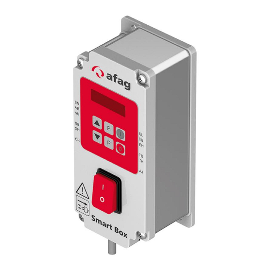
Design and function Design and function Design of the controller Display Controller Menu On-/Off switch Fig. 3 Design of the Smart Box controller Functional description The Smart Box is used for vibratory conveyor technology to link external controllers, sensors, and valves to form self-sufficient functional units. The Smart Box can be used to create the necessary functional links for a complete feeding station with linear, spiral and hopper conveyors. -
Page 17: Mounting And Installation
Mounting and installation Mounting and installation For safe operation, the module must be integrated into the safety concept of the system in which it is installed. The system operator is responsible for the installation of the controller in a system! Safety instructions DANGER Risk of injury due to electric shock! -
Page 18: Assembly
Mounting and installation Assembly Two holes are provided on the lower part of the housing for fastening the controller. These are separated from the interior of the housing. Fig. 4 Fixing holes for the Smart Box 18 – 32 Operating instructions EN ◼... -
Page 19: Electrical Connection
Mounting and installation Electrical connection DANGER Risk of injury due to electric shock! Work on the electrical system carried out unprofessionally can cause serious or fatal injuries. ▪ Work on the machine's electrical equipment may only be performed by skilled electrician or trained personnel under the supervision of a skilled electrician in accordance with all relevant electrical regulations. -
Page 20: Operation And Settings
Operation and settings Operation and settings Safety instructions NOTICE Damage of the controller! If the controller plug is plugged in or unplugged from the vibratory drive when the controller is switched on, the controller may be damaged! ▪ Never connect or disconnect the device plug to the vibratory drive when the controller is switched on! General notes on settings Basic settings:... - Page 21 Operation and settings Description of the messages: Messages Linear feeder filling process Stop via button System release = "Off" with the bowl feeder switched off Description of the Smart Box displays: Fig. 6 Smart Box displays Operating instructions EN ◼ Smart Box ◼...
-
Page 22: Settings
Operation and settings Settings 7.4.1 Setting options Setting options Area Code Factory Menu settings code Invert system release 0 / I Switch-on delay hopper conveyor 099.9 Sec. u.1. 1.0 Sec. Switch-off delay hopper conveyor 099.9 Sec. u.0. 1.0 Sec. Sensor invert hopper conveyor 0 / I u.-S. -
Page 23: System Release - Code C 003
Operation and settings 7.4.2 System release - Code C 003 Input E1 +24 V signal or closed +24 V signal or closed contact releases output contact blocks output Operating instructions EN ◼ Smart Box ◼ 17.02.2024 ◼ Version 3.0 23-32... -
Page 24: Hopper Conveyor Level Control - Code C 004
Operation and settings 7.4.3 Hopper conveyor level control - Code C 004 Sensor input E2, output A3 Setting the switch-on and switch-off delay Invert sensor function Output clocks with adjustable ON-OFF times Setting the cycle time 24 – 32 Operating instructions EN ◼... -
Page 25: Bowl Feeder Status Line, Air Jet - Code C 007
Operation and settings 7.4.4 Bowl feeder status line, air jet - Code C 007 Sensor input E3, air jet A1, output A4 Setting the switch-on and switch-off delay (without air jet) Invert sensor input Air jet Additional setting of the lead and after-running time for 24 V blast air output. To deactivate the air jet: set b.1 to 0.0 sec. -
Page 26: Sensor Time-Out (Empty Signal) - Code C 015
Operation and settings 7.4.5 Sensor time-out (empty signal) - Code C 015 Output A2 Time-out STOP Activate STOP sensor monitoring. If no conveyor section is detected after the set time-out time has elapsed, a 24 V, DC signal is generated. With set o.E.E. -
Page 27: Block Access - Code C 117
Operation and settings 7.4.6 Block access - Code C 117 Hide program menus 7.4.7 Saving user parameters - Code C 143 7.4.8 Load user parameters - Code C 210 Operating instructions EN ◼ Smart Box ◼ 17.02.2024 ◼ Version 3.0 27-32... -
Page 28: Maintenance
The process is completed. Spare and wear parts, repairs Afag offers a reliable repair service. Defective devices can be sent to Afag for warranty repair within the warranty period. Repair work may only be carried out by qualified personnel! We recommend that you have the repair carried out at our premises. -
Page 29: Decommissioning And Disposal
Decommissioning and disposal Decommissioning and disposal The controller must be properly dismounted after use and disposed of in an environmentally friendly manner. Safety instructions WARNING Risk of injury due to improper decommissioning and disposal! Improperly carried out activities can result in considerable material damage and severe injury. - Page 30 30 – 32 Operating instructions EN ◼ Smart Box ◼ 17.02.2024 ◼ Version 3.0...
- Page 31 Operating instructions EN ◼ Smart Box ◼ 17.02.2024 ◼ Version 3.0 31-32...
- Page 32 32 – 32 Operating instructions EN ◼ Smart Box ◼ 17.02.2024 ◼ Version 3.0...
Need help?
Do you have a question about the 50371863 and is the answer not in the manual?
Questions and answers