
Subscribe to Our Youtube Channel
Related Manuals for Afag SE-24


Summary of Contents for Afag SE-24
- Page 1 Servo Controller SE-24 Software Manual ▪ Complementary document to the Operating Instructions © Copyright by Afag Automation AG...
- Page 2 50315432 Installation and start-up is to be performed only by qualified personnel in accordance with the operating instructions. Version of this SE-24-Software-Manual vers. 1.3 en. 01.06.2022 documentation: CAUTION As this manual is a complementary document to the operating instructions it alone is not sufficient to carry out installation and commissioning of the device.
- Page 3 Disregard of this information can result in damage to property or light to medium personal injuries. NOTE Indicates general notes, useful operator tips and operating recommendations which don't affect safety and health of the personnel. ◼ ◼ ◼ Software Manual EN SE-24 01.06.2022 V1.3 3–54...
-
Page 4: Table Of Contents
Overview of the tools and functions ..................8 Installation Hardware requirements ....................... 9 Installation of the afagTools program................... 9 Connection .........................10 4.3.1 SE-24 programming cable, 3m (50315431) ...............10 4.3.2 SE-24 stick (50315432) .....................10 4.3.3 Installation of the SE-24 stick .....................11 Working with afagTools Starting the program ......................16... - Page 5 List of Figures Figure 1: SE-24 programming cable ......................10 Figure 2: SE-24 stick ..........................10 Figure 3: Positioning mode ........................40 Figure 4: Current mode ..........................41 Table 1: Checklist for commissioning .....................48 ◼ ◼ ◼ Software Manual EN SE-24 01.06.2022 V1.3 5–54...
-
Page 6: General
SE-24 servo controller. It is meant for persons who want to get familiar with the SE-24 servo controller. CAUTION The operating manual is the main document and must be read by all means before installation and start-up of all devices of the SE-24 series independent of the respective model. - Page 7 Description of the I/O control of the SE-24 servo controller. ☐ ▪ SE-24 Profibus Manual Description of the fieldbus control of the SE-24 servo controller under PROFIBUS-DP. ☐ ▪ SE-24 programming example Siemens S7 V5.5 Description to the programming example for Siemens S7 V5.5.
-
Page 8: Safety Instructions
3.1 Overview of the tools and functions The afagTools program provides a parameterization software that makes commissioning of the SE-24 servo controller with the corresponding Afag module easy and more convenient. Commissioning is possible even when no higher level controller (PLC) is connected. The afagTools program is easy to operate and enables a quick and comfortable commissioning. -
Page 9: Installation Hardware Requirements
Main memory: min. 512MB Interface: one free USB interface (V2.0 downward compatible with V1.1) 4.2 Installation of the afagTools program The afagTools program can be downloaded and saved free of charge from the Afag Automation AG website using the following link: http://www.afag.com/produkte/download/download-handling-elektrisch.html Unpack the file afagTools-V1.xx.yy.zz-Setup.zip with a suitable program (WinZip, 7-... -
Page 10: Connection
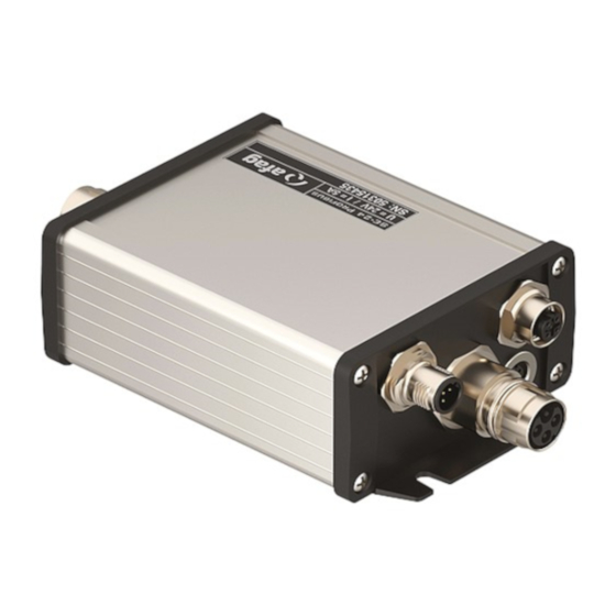
The SE-24 stick is needed together with the SE-24 programming cable if the “afagTools” parameterization program is used to access the controller. The SE-24 stick is the gateway from USB to CANopen and can be used for all types of the SE-24 servo controller. -
Page 11: Installation Of The Se-24 Stick
SE-24 stick. Administrator rights are required on the corresponding PC. After the „afagTools“ software was installed on the computer, the SE-24 stick can be plugged into a free USB connection. The following window will open when the device is recognized: Select “No, not this time”... - Page 12 The following window will be displayed: Select option “Install software from a list or a specific location (for advanced users)” and click “Continue >”. ◼ ◼ ◼ 12–54 Software Manual EN SE-24 01.06.2022 V1.3...
- Page 13 The following window appears: Select options “Search the following locations for matching driver” and also “Search the following location”. Then click on “Browse”. ◼ ◼ ◼ Software Manual EN SE-24 01.06.2022 V1.3 13–54...
- Page 14 The following window appears: In the installation directory select the “USB” folder of the “afagTools” program. The default path is: „C:\Programs\miControl\mPLC\Drivers\USB“ Then click on “OK”. ◼ ◼ ◼ 14–54 Software Manual EN SE-24 01.06.2022 V1.3...
- Page 15 The path will also be displayed in the following window: Click on “Continue >” when the path is displayed correctly. The following window opens: Click on “Complete”. This finishes the installation of the SE-24 stick. ◼ ◼ ◼ Software Manual EN SE-24 01.06.2022...
-
Page 16: Working With Afagtools
Start/Programs/miControl mPLC/afagTools. 5.2 Main window After starting the program the main window will open. The main window is divided in a number of areas which are explained hereafter. ◼ ◼ ◼ 16–54 Software Manual EN SE-24 01.06.2022 V1.3... -
Page 17: Support
He however first has to specify a code so that a session can be started and is contact person only for program-technical questions and not for an application-oriented support which is guaranteed by Afag Automation 5.2.2 Language The language can be selected via the function “Configuration ->... -
Page 18: Connection
A connection can only be established if the SE-24 stick is inserted in the PC and is correctly connected to the SE-24 servo controller via the SE-24 programming cable. The required settings for establishing a connection to the SE-24 servo controller can be made in the “Connection” area. Node ID... - Page 19 „Connect device“. If only one device was found a connection will already be established without entering the ID in the “Node ID” box and without pressing the “Connect device” button. ◼ ◼ ◼ Software Manual EN SE-24 01.06.2022 V1.3 19–54...
-
Page 20: Device Informations
Information about the connected device are displayed in the “Device informations” area. Firmware version Version currently loaded firmware. Device code Individual code with which every device can be identified. 5.2.5 Tools The “Tools” area provides the overview of all functions available. ◼ ◼ ◼ 20–54 Software Manual EN SE-24 01.06.2022 V1.3... - Page 21 After a tool was selected a short description will be displayed in this area. The tools are only released when there is an active connection to a device. ◼ ◼ ◼ Software Manual EN SE-24 01.06.2022 V1.3 21–54...
-
Page 22: Status
Device informations Max. power voltage Maximum voltage which may be applied to the power voltage input of the SE-24 servo controller. Power supply connector X1, pin 3. Max. motor current Maximum current that can be supplied from the SE-24 servo controller to a motor. - Page 23 SVelocity Current target rotational speed for the secondary speed controller. Is only used in the “Vel” (rotational speed) operating mode. Not relevant for the SE-24. Position Current target position Comment: The unit [Ink] is the default setting. Depending on the application the value is however displayed in the following units: translatory: [µm] (um)
- Page 24 Currently set speed limitation for movements in counter clockwise direction. Comment: The unit [rpm] is the default setting. Depending on the application the value is however displayed in the following units: translatory: [mm/s] rotary: [°/s] ◼ ◼ ◼ 24–54 Software Manual EN SE-24 01.06.2022 V1.3...
- Page 25 -6700µm -1000µm – Reference offset Pos.limit max. = pos. software end position – (-5700µm) 15300µm = 21000µm The SG-50 servo gripper thus has the following positioning range: -1000µm to 21000µm ◼ ◼ ◼ Software Manual EN SE-24 01.06.2022 V1.3 25–54...
- Page 26 Error code Current device error code Comment: For explanations on the error please refer to the document: “SE-24 operating instructions”, table „Error Register“ Status bits Current actual status of the status bits of the device Blockage status bits Current actual status of the blocking monitoring...
-
Page 27: Can Configuration
3. Set the Node ID and the baudrate in the following window and confirm with “Set”: 4. Important: Changes are only retrieved when the controller is restarted. 5.4.1 CAN baudrate The default transmission speed of the SE-24 servo controller is 125kBit/s and can be set up to maximum 1MBit/s. ◼ ◼... -
Page 28: Profibus Configuration
3. Set the Profibus-Slave address in the following window and confirm with “Set”: 4. Important: The address is only retrieved when the controller is restarted. 5.5.1 Profibus baud rate The SE-24 servo controller automatically detects the baud rate of the Profibus communication and supports speeds up to max. 12Mbaud. ◼ ◼... -
Page 29: Firmware Update
The “Firmware update” tool updates or changes the firmware of the device. CAUTION A firmware update deletes all parameters incl. the loaded application which are stored on the SE-24 servo controller. A firmware update should therefore only be executed if absolutely... - Page 30 “Open” button: 5. Click the “START update” button to load the desired firmware: 6. Important: CAUTION After a firmware update the SE-24 servo controller is not ready to operate if the application and parameters were not loaded. ◼ ◼...
-
Page 31: Parameters Download
5.7 Parameters Download The “Parameters download” tool updates or changes application-specific parameters. NOTE Afag Automation AG generates and provides the parameter sets for applications with Afag handling modules. The parameter files are identified by the extension *.par. Carry out the following steps to load a parameter file: 1. - Page 32 5. Activate the “Save parameters at the of programming” option and load the selected Parameter file by clicking the “START Download” button: Activate the „Save parameters at the end of programming“ option. ◼ ◼ ◼ 32–54 Software Manual EN SE-24 01.06.2022 V1.3...
-
Page 33: Manual Operation
Applies only to the SE-24 CANopen model The communication via CANopen to a higher level control system (PLC) must be stopped if the functions of the “Manual operation” tool are to be used for the models of the SE-24 CANopen series. ◼ ◼... -
Page 34: Commands
A current movement is stopped immediately. Homing Starts the reference run. Comment: This function is only active if the controller enable was activated. CAUTION A movement is triggered after the “Homing” button was actuated. ◼ ◼ ◼ 34–54 Software Manual EN SE-24 01.06.2022 V1.3... -
Page 35: Actual Application Status
Current actual application status in hexadecimal notation. Status bits Detailed information are to be found in the interface descriptions of the corresponding manuals for the various SE-24 servo controller models. Ready The device is ready-to-operate, there are no active errors pending. -
Page 36: Actual Device Status
Error code Current device error code Comment: For explanations on the error please refer to the document: “SE-24 operating instructions”, table „Error Register“ Status bits Enabled The controller is active and the motor is energized. Comment: Corresponds to the “drive_enable_ok” interface signal. - Page 37 The current limit is reached. Limit - velocity The speed limit is reached. Limit - position The position limit is reached. Limit - svelocity The limit for the secondary speed controller is active. ◼ ◼ ◼ Software Manual EN SE-24 01.06.2022 V1.3 37–54...
-
Page 38: Actual Values
5.8.4 Actual values Interface objects Detailed information about the objects which are also interface objects are to be found in the interface descriptions of the corresponding manuals for the various SE-24 servo controllers models. Current Current actual current Comment: Corresponds to the “current_value” interface object (not available for the SE-24 I/O model). -
Page 39: Jog Mode
When the button is released the drive is braked until stop with the deceleration set for the quick stop. Comment: The function is only active when controller enable was activated. A reference run does not have to be executed. ◼ ◼ ◼ Software Manual EN SE-24 01.06.2022 V1.3 39–54... -
Page 40: Settings
The values in the “Settings” area only refer to the “Move OK” signal which corresponds to the “move_ok” interface signal. Detailed information about the functions are to be found in the function description of the SE-24 operating instructions, chapter “Function description”. Settings for the “Move OK” signal in positioning mode. - Page 41 Comment: The “Move OK” signal is triggered after the current fade out time and the delay time for the current in the current window have passed. X = position_value (actual position) Y = target_position (abortion position) Current = target_current Figure 4: Current mode ◼ ◼ ◼ Software Manual EN SE-24 01.06.2022 V1.3 41–54...
-
Page 42: Moving Data Sets
The moving data sets are used in the following cases: • for commissioning of the servo controller and the corresponding servo axis • for operation of the SE-24 I/O servo controller • for operation of the servo controllers with fieldbus connection only when the moving data sets are controlled via the "pos_nr_bit0 to 3"... - Page 43 A maximum of 15 moving data sets with the following contents can be stored on the SE-24 servo controller: Position Target position The target position value is interpreted as an absolute or relative value depending on the “Relative positioning” option.
- Page 44 The input values are stored permanently on the servo controller after this button was actuated. NOTE Changes are only maintained after a restart of the controller if they were stored by clicking the “Store in device” button. ◼ ◼ ◼ 44–54 Software Manual EN SE-24 01.06.2022 V1.3...
-
Page 45: Reverse Mode
Changes of the moving data sets used for the reverse mode are ignored when reverse mode is active. The reverse mode must be stopped and then restarted again in order to retrieve the changes. ◼ ◼ ◼ Software Manual EN SE-24 01.06.2022 V1.3 45–54... -
Page 46: Saving Position Values To A File
The values set in the “Manual operation” tool should be saved to a file. Select the “File/Save as” function from the “Manual operation” tool. Select the desired directory in the window which opens and save the file by clicking the "Save" button. ◼ ◼ ◼ 46–54 Software Manual EN SE-24 01.06.2022 V1.3... -
Page 47: Loading Position Values From A File
Open the desired directory in the window which now opens and select the file. The file will be loaded into the servo controller by clicking the “Open” button. ◼ ◼ ◼ Software Manual EN SE-24 01.06.2022 V1.3 47–54... -
Page 48: Quick Guide For Commissioning
6 Quick guide for commissioning All steps required for commissioning of an SE-24 servo controller with the corresponding Afag handling module are described hereafter in short. The standard procedure will be described. This procedure is only an example and can vary depending on the application. - Page 49 Step Work to be done Ensure that the power supply to the SE-24 servo controller (SE-24/SE-48 power cable, wire no. 3) can be disconnected by a suitable Emergency- Stop switching device if necessary. The electronics supply and ground (SE-24/SE-48 power cable, wires 2 + 1) must however be maintained.
- Page 50 Step Work to be done You can skip this step for the SE-24 I/O and the SE-24 EtherCAT models. Set the device address for the SE-24 CANopen and the SE-24 Profibus models. Open the corresponding tool, i.e. “CAN configuration” or “Profibus configuration”.
- Page 51 Now connect the interface cables to a higher level control system (PLC). Depending on the controller model this applies to the following cables: The SE-24 I/O cable for the SE-24 I/O servo controller. The bus cables for servo controllers with fieldbus connection (Profibus, EtherCAT, CANopen).
- Page 52 Please see the manual on the corresponding servo controller model for more information about the individual interfaces. If an SE-24 I/O servo controller is used or the moving sets are used with a fieldbus variant, then select the corresponding (and previously tested) moving set via the "pos_nr_bit0 to 3"...
- Page 53 ◼ ◼ ◼ Software Manual EN SE-24 01.06.2022 V1.3 53–54...
- Page 54 Afag Automation AG Luzernstrasse 32 CH-6144 Zell Switzerland Phone: +41 (0)62 959 86 86 Fax: +41 (0)62 959 87 87 e-mail: sales@afag.com Internet: www.afag.com...
Need help?
Do you have a question about the SE-24 and is the answer not in the manual?
Questions and answers