Table of Contents
Advertisement
Quick Links
Frequency controller
Translation of the Original Operating Instructions EN
Frequency controller SIGA (V6) (230 VAC; 50 Hz / 60 Hz)
Frequency controller SIGA (V6) (115 VAC; 50 Hz / 60 Hz)
Operating instructions EN
Operating Instructions
SIGA (V6)
SIGA
07.04.2024
Order no: 50195031
Order no.: on request
Version 3.0
1-44
Advertisement
Table of Contents

Subscribe to Our Youtube Channel
Related Manuals for Afag SIGA (V6)


Summary of Contents for Afag SIGA (V6)
- Page 1 Operating Instructions Frequency controller SIGA (V6) Translation of the Original Operating Instructions EN Frequency controller SIGA (V6) (230 VAC; 50 Hz / 60 Hz) Order no: 50195031 Frequency controller SIGA (V6) (115 VAC; 50 Hz / 60 Hz) Order no.: on request ...
- Page 2 Your Afag team © Subject to modifications The controllers have been designed by Afag GmbH according to the state of the art. Due to the constant technical development and improvement of our products, we reserve the right to make technical changes at any time.
-
Page 3: Table Of Contents
Table of contents Table of contents General ........................5 Contents and purpose of this manual ............5 Explanation of symbols................. 5 Additional symbols ..................6 Warranty ....................... 7 Liability ......................7 Safety instructions ....................8 General ......................8 Intended use ....................8 Foreseeable misuse .................. - Page 4 Table of contents Commissioning ................... 21 6.4.1 Settings before commissioning ............21 6.4.2 Commissioning ..................22 Operation ......................23 Safety instructions ..................23 Keyboard and displays ................24 7.2.1 Switch on the device ................25 7.2.2 Display of the control unit ..............25 7.2.3 Parameter setting .................
-
Page 5: General
General General Contents and purpose of this manual These operating instructions contain valuable information on assembly, commissioning, functioning and maintenance of the controller to ensure safe and efficient handling and operation. Consistent compliance with these operating instructions will ensure: permanent operational reliability of the frequency controller, ... -
Page 6: Additional Symbols
General This note contains important additional information as well as useful tips for safe, efficient, and trouble-free operation of the frequency controller. Further warning signs: Where applicable, the following standardized symbols are used in this manual to point out the various potential health risks. Warning - Dangerous electrical voltage. -
Page 7: Warranty
This does also apply to defective accessories and wear parts. Normal wear and tear are excluded from the warranty. The warranty covers the replacement or repair of defective Afag parts. Further claims are excluded. The warranty shall expire in the following cases: ... -
Page 8: Safety Instructions
Safety instructions Safety instructions General This chapter provides an overview of all important safety aspects to ensure safe and proper use of the frequency controller and optimal protection of personnel. Safe handling and trouble-free operation of the controller requires knowledge of the basic safety regulations. -
Page 9: Obligations Of The Operator And The Personnel
Safety instructions Obligations of the operator and the personnel 2.4.1 Follow these instructions A basic prerequisite for safe and proper handling of the frequency controller is a good knowledge of the basic safety instructions. This manual, particularly the safety instructions contained therein, must be observed by all persons working with the frequency controller. -
Page 10: Personnel Requirements
Safety instructions Personnel requirements 2.5.1 Personnel qualification The activities described in the assembly instructions require specific requisites at the level of professional qualifications of the personnel. Personnel not having the required qualification will not be able to assess the risks that may arise from the use of frequency controller thus exposing himself and others to the risk of severe injury. -
Page 11: Changes And Modifications
Changes and modifications No changes may be made to the controller which have not been described in these operating instructions or approved in writing by Afag GmbH. Afag accepts no liability for unauthorized changes or improper assembly, installation, commissioning, maintenance, or repair work. -
Page 12: Technical Data
Technical data Technical data Dimensional drawing SIGA Fig. 1 Dimensional drawing frequency controller SIGA 3.2 Technical data 12 - 44 Operating instructions EN SIGA 07.04.2024 Version 3.0 ... -
Page 13: Transport And Storage
Transport and storage Transport and storage Scope of supply The corresponding documentation is supplied with each frequency controller. Fig. 2 Scope of delivery SIGA [Unt] Designation Frequency controller Operating Instructions Operating instructions EN SIGA 07.04.2024 Version 3.0 13-44 ... -
Page 14: Transport
Relative air humidity: < 90%, non condensing Packaging The frequency controller is delivered in the Afag GmbH transport packaging. If no Afag packaging is used, the controller must be packed in such a way that it is protected against shocks and dust. NOTICE Risk to the environment due to incorrect disposal of the packaging material. -
Page 15: Design And Description
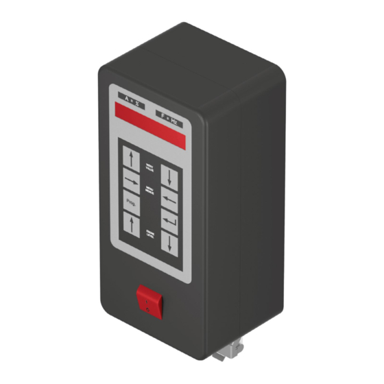
Design and description Design and description Design of frequency controller Display Controller Menu On-/Off switch Fig. 3 Design of the frequency controller SIGA Even the smallest solenoids can be operated safely with the frequency controller SIGA! Operating instructions EN SIGA 07.04.2024 Version 3.0 15-44... -
Page 16: Description
Design and description Description The frequency controller SIGA is used for the control of inductive loads such as bowl feeders and linear feeders. The controller works according to the principle of pulse width modulation (PWM) within the half-waves with an adjustable period between 20 Hz and 99 Hz. -
Page 17: Mounting, Installation And Commissioning
Mounting, installation and commissioning Mounting, installation and commissioning For safe operation, the module must be integrated into the safety concept of the system in which it is installed. The system operator is responsible for the installation of the controller in a system! Safety instructions DANGER... -
Page 18: Assembly
Mounting, installation and commissioning Assembly Fastening the controller Two holes are provided on the lower part of the housing for mounting the controller. These are separated from the interior of the housing. Fig. 4 SIGA controller mounting holes Procedure: 1. Loosen the cover fastening screws. 2. -
Page 19: Installation / Electrical Connection
Mounting, installation and commissioning Installation / electrical connection DANGER Risk of injury due to electric shock! Work on the electrical system carried out unprofessionally can cause serious or fatal injuries. Work on the machine's electrical equipment may only be performed by skilled electrician or trained personnel under the supervision of a skilled electrician in accordance with all relevant electrical regulations. -
Page 20: Connection Options
Mounting, installation and commissioning 6.3.1 Connection options Fig. 5 Connection options for SIGA controller 6.3.2 Important notes on the electrical connection Disconnect the supply voltage before assembly or disassembly work, as well as when changing fuses or modifying the structure. ... -
Page 21: Notes On The High Voltage Test
Mounting, installation and commissioning 6.3.3 Notes on the high voltage test The following safety-relevant points must be observed during the high voltage test: L and N must be connected to each other! Test voltage must not be higher than 1000 VAC! ... -
Page 22: Commissioning
Mounting, installation and commissioning 6.4.2 Commissioning Procedure for commissioning: 1. Before commissioning, check whether the rated voltage of the device matches the local mains voltage. 2. Plug in the mains plug of the controller. 3. Switch on the controller. 4. Set the operating frequency of the vibratory feeder according to the setting instructions on the keypad. -
Page 23: Operation
Operation Operation Safety instructions NOTICE Damage to the frequency controller! If the controller plug is plugged in or unplugged from the vibratory drive when the controller is switched on, the controller may be damaged! Never connect or disconnect the device plug to the vibratory drive when the controller is switched on! NOTICE Damage to the controller due to incorrect control input! -
Page 24: Keyboard And Displays
Operation Keyboard and displays For reasons of simplification and standardization, the following sections describe how the task is performed using the keyboard. Fig. 6 SIGA keypad and display 24 - 44 Operating instructions EN SIGA 07.04.2024 Version 3.0 ... -
Page 25: Switch On The Device
Operation 7.2.1 Switch on the device To adjust the controller, proceed as follows: 1. Check that the plug connection to the vibratory bowl feeder is correct. 2. Switch on the control unit with a mains switch. After an initialization phase, the control unit is ready for operation. The following messages appear one after the other on the display: Here: SIGA system Day, month, year of compilation... -
Page 26: Parameter Setting
Operation 7.2.3 Parameter setting Symbol Description Programming button To change the value of a parameter, the system must be set to programming mode. Pressing this button once prompts the system to authorize changes. Some areas of the parameters are protected with a ... -
Page 27: Overview Of Parameter Levels
Operation Manual setting: Briefly pressing the value buttons increases/decreases/changes the displayed value by one digit (one, tenth or letter). Automatic setting: If the buttons remain pressed, the system first switches to continuous operation and after 3 seconds to fast operation: The values increase/decrease/change automatically at different speeds. -
Page 28: Parameter Level 0
Operation 7.3.1 Parameter level 0 Parameter Display Explanation Defines the amplitude (output voltage) as a percentage. Value between 10 and 99 in increments of 1. 10 = min. set output voltage. 99 = max. set output voltage. Defines the oscillation frequency for the oscillating drive. -
Page 29: Parameter Level 6 (Rolling Sequence Of Parameters)
Operation Parameter Display Explanation Defines the mode in which the vibratory drive should operate. Value adjustable to G and H. G = Full wave operation (El. oscillation - current - above and below the zero line) H = Half-wave operation (electrical oscillation - current - only on one side of the zero line, the other side is faded out) Defines the mode in which the vibratory drive... -
Page 30: Parameter Level B
Operation 7.3.3 Parameter level b Parameter Display Explanation Defines a logic element with the value S or O. The logic signal applied to the input (logic LO when the vibratory drive is running, logic HI when the vibratory drive is stationary) is processed according to the set value as follows (i.e., signal inverted or not inverted): O = logical HI applied remains HI (not... -
Page 31: Parameter Level 0 (Rolling Sequence Of Parameters)
Operation 7.3.4 Parameter level 0 (rolling sequence of parameters) Parameter Display Explanation Parameter L specifies the logical connection of the selected inputs in relation to the vibratory drive. AND (U), OR (O), STAU (S) can be selected as the link. All programmable inputs offered by the software are available. -
Page 32: Amplitude Setting
Operation 7.3.5 Amplitude setting Original display Press the key Dot appears in second LED Programming mode active Amplitude can be changed Set value Example: Value set to 75 Press button, save change Confirmation that changes were saved If no button is pressed for 20 seconds, programming mode is exited, and the original display is shown without a dot. -
Page 33: Frequency Setting
Operation 7.3.6 Frequency setting Original display Press the button Parameter Frequency set to 50.0 Hz is displayed. Press the button The code input is expected Press the button Press the button Press the button Press the button a dot appears in the second LED Programming mode active the value can be set using the value buttons. -
Page 34: Setpoint Setting
Operation 7.3.7 Setpoint setting Original display Press the button Parameter frequency set to 50.0 Hz is displayed. Press the button Press the button The code input is expected Press the button Press the button Press the button Press the button A dot appears in the second LED Programming mode active. -
Page 35: Invert Control Signal (Here Input E6)
Operation 7.3.8 Invert control signal (here input E6) Original display Press the button Press the button code input is expected Press the button Press the button Press the button Press the button a dot appears in the second LED Programming mode active the value can be set using the value buttons. -
Page 36: Remaining Parameters
Operation 7.3.9 Remaining parameters All other available parameters must be programmed in the same way as follows: 1. Moving to the parameter point. 2. Activate programming mode via CODE. 3. Change value. 4. Save. Truth tables (examples) Truth table for AND operation and F1 = O for E6 and Eb Input E6 Input Eb Output A0... - Page 37 Operation Truth table for STAU link and F1 = O for E6 and Eb Input E6 Input Eb Flag Output A0 runni running runnin runni Truth table for STAU link and F1 = S for E6 and Eb (F1 inverts the input signals) Input E6 Input Eb...
-
Page 38: Status Display Of The Inputs And Outputs
Operation Status display of the inputs and outputs Only in display mode 1st parameter - point in the second LED is off / signal levels are inverted as soon as F1 is programmed as S. Drive running. Drive stopped. There is no signal at the sensor input. Signal level LO is processed further. -
Page 39: Fault Elimination
Fault elimination Fault elimination Safety instructions The safety instructions in chap. 2 "Safety instructions" of these installation instructions and the safety instructions of the manufacturer of the frequency controller must be observed. Fault causes and remedy The following table contains an overview of fault causes and how to proceed to eliminate them. -
Page 40: Maintenance And Repair
Replace the fuse as needed: Spare and wear parts, repairs Afag GmbH offers a reliable repair service. Defective devices can be sent to Afag for warranty repair within the warranty period. Repair work may only be carried out by qualified personnel! We recommend that you have the repair carried out at our premises. -
Page 41: 10 Decommissioning And Disposal
Decommissioning and disposal 10 Decommissioning and disposal The controller must be properly dismounted after use and disposed of in an environmentally friendly manner. 10.1 Safety instructions WARNING Risk of injury due to improper decommissioning and disposal! Improperly carried out activities can result in considerable material damage and severe injury. - Page 42 42 - 44 Operating instructions EN SIGA 07.04.2024 Version 3.0 ...
- Page 43 Operating instructions EN SIGA 07.04.2024 Version 3.0 43-44 ...
- Page 44 44 - 44 Operating instructions EN SIGA 07.04.2024 Version 3.0 ...
Need help?
Do you have a question about the SIGA (V6) and is the answer not in the manual?
Questions and answers