Table of Contents
Advertisement
Quick Links
Advertisement
Table of Contents

Related Manuals for Afag IRG1-S


Summary of Contents for Afag IRG1-S
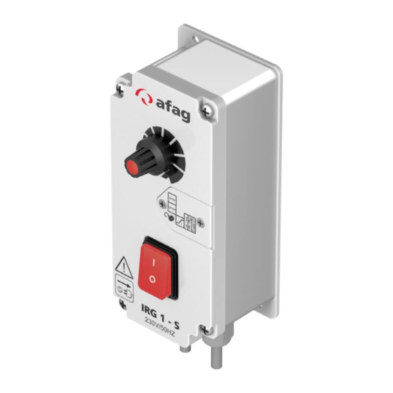
- Page 1 Operating Instructions Controller IRG1-S Translation of the Original Operating Instructions EN Controller IRG1-S (230 V/50 Hz) Order no: 50360105 ◼ Controller IRG1-S (115 V/60 Hz) Order no: 50360106 ◼ Operating instructions EN ◼ IRG1-S ◼ 17.02.2024 ◼ Version 3.0...
- Page 2 Your Afag team © Subject to modifications The controllers have been designed by Afag GmbH according to the state of the art. Due to the constant technical development and improvement of our products, we reserve the right to make technical changes at any time.
-
Page 3: Table Of Contents
General hazards / residual risks ..............11 2.8.1 General hazards at the workplace ............11 2.8.2 Danger due to electricity ..............11 Technical data ...................... 12 Dimensional drawing controller IRG1-S ............. 12 Technical data controller IRG1-S ............... 13 Accessories ....................13 3.3.1 Support ....................13 Transport and storage .................. - Page 4 8.2.1 Maintenance point ................26 8.2.2 Replacing the fuse................26 Spare and wear parts, repairs ..............26 Decommissioning and disposal ................. 27 Safety instructions ..................27 Disposal ...................... 27 4 - 28 Operating instructions EN IRG1-S 17.02.2024 Version 3.0 ◼ ◼ ◼...
-
Page 5: General
General Contents and purpose of this manual These assembly instructions contain important information on assembly, commissioning, functioning and maintenance of the controller IRG1-S to ensure safe and efficient handling and operation. Consistent compliance with these operating instructions will ensure: ▪ permanent operational reliability of the controllers, ▪... -
Page 6: Additional Symbols
In these assembly instructions the following symbols are used to highlight instructions, results, references, etc. Symbol Description Instructions (steps ...) Results of actions References to sections ◼ Enumerations not ordered 6 - 28 Operating instructions EN ◼ IRG1-S ◼ 17.02.2024 ◼ Version 3.0... -
Page 7: Warranty
General Warranty The warranty terms for Afag feeding components and handling systems are the following: ▪ 24 months from initial operation and up to a maximum of 27 months from delivery. ▪ Wear parts are excluded from the warranty (The customer is entitled to a product free of defects. -
Page 8: Safety Instructions
▪ The controllers may only be used in a technically perfect condition in accordance with its intended use and the instructions in this manual as well as in compliance with the safety requirements! 8 - 28 Operating instructions EN ◼ IRG1-S ◼ 17.02.2024 ◼ Version 3.0... -
Page 9: Obligations Of The Operator And The Personnel
▪ refrain from any activity that might compromise safety and health. In addition, the personnel must wear the personal protective equipment required for carrying out their work. ( chap. 2.6). Operating instructions EN ◼ IRG1-S ◼ 17.02.2024 ◼ Version 3.0 9-28... -
Page 10: Personnel Requirements
▪ check the personal protective equipment for proper condition, and ▪ immediately notify the person responsible on site of any defects found on the personal protective equipment. 10 - 28 Operating instructions EN ◼ IRG1-S ◼ 17.02.2024 ◼ Version 3.0... -
Page 11: Changes And Modifications
Changes and modifications No changes may be made to the controller which have not been described in these operating instructions or approved in writing by Afag GmbH. Afag accepts no liability for unauthorised changes or improper assembly, installation, commissioning, maintenance, or repair work. -
Page 12: Technical Data
Technical data Technical data Dimensional drawing controller IRG1-S Fig. 1 Dimensional drawing of IRG1-S controller 12 - 28 Operating instructions EN ◼ IRG1-S ◼ 17.02.2024 ◼ Version 3.0... -
Page 13: 3.2 Technical Data Controller Irg1-S
Technical data 3.2 Technical data controller IRG1-S Accessories 3.3.1 Support Type Designation Order Number for 1 IRG 50450178 for 2 IRG 50450179 Support for 1 IRG extended 50450145 for 2 IRG extended 50450147 Operating instructions EN ◼ IRG1-S ◼ 17.02.2024 ◼... -
Page 14: Transport And Storage
Transport and storage Transport and storage Scope of supply The corresponding documentation is supplied with each controller. Fig. 2 Scope of delivery IRG1-S [Unt] Designation Controller Operating Instructions 14 - 28 Operating instructions EN ◼ IRG1-S ◼ 17.02.2024 ◼ Version 3.0... -
Page 15: Transport
▪ The storage space must be dry and dust free. ▪ Room temperature of the storage space: 0-50 °C. ▪ Relative air humidity: < 90% non-condensing. ▪ Protect the controller from dirt and dust. Operating instructions EN ◼ IRG1-S ◼ 17.02.2024 ◼ Version 3.0 15-28... -
Page 16: Design And Function
Fig. 3 Design of the IRG1-S controller Functional description The electronic controller IRG1-S is used for the control of inductive loads such as bowl feeders and linear feeders. The controller operates according to phase-angle control and thus generate a variable output voltage for the drive solenoid. -
Page 17: Mounting And Installation
Observe the safety instructions in chap. 2 "Safety instructions" of this manual as well as the instructions in chap. 6.3. Operating instructions EN ◼ IRG1-S ◼ 17.02.2024 ◼ Version 3.0 17-28... -
Page 18: Mounting The Controller
▪ Set the slide switch only for the respective application! Connection option type 230V/50Hz Output coupling STAK 20 Sensor plug M8 - 4 pol. Fig. 4 Fastening of controller type 230V/50Hz 18 - 28 Operating instructions EN ◼ IRG1-S ◼ 17.02.2024 ◼ Version 3.0... - Page 19 Mounting and installation Connection option type 115V/60Hz Output coupling STAK 20 Sensor plug M8 - 4 pol. Fig. 5 Fastening of controller type 115V/60Hz Operating instructions EN ◼ IRG1-S ◼ 17.02.2024 ◼ Version 3.0 19-28...
-
Page 20: Installation
Unlocking the Emergency-STOP devices must not cause an uncontrolled restart! ▪ The electrical connections must be covered! ▪ Protective conductor connections must be checked for proper function after installation! 20 - 28 Operating instructions EN ◼ IRG1-S ◼ 17.02.2024 ◼ Version 3.0... -
Page 21: Operation And Settings
The standard settings can be made without removing the front panel. The adjustment elements are accessible after unscrewing the flap on the right-hand side of the front panel. Setting options: Fig. 6 Setting options on the IRG1-S Operating instructions EN ◼ IRG1-S ◼... -
Page 22: Setting Of Control Characteristic (Internal Potentiometer)
115 V devices: Umin 20 V, Umax 105 V). As the Umax trimmer influences the Umin trimmer, the Umax trimmer should be adjusted first and then the Umin trimmer when changing the setting. 22 - 28 Operating instructions EN ◼ IRG1-S ◼ 17.02.2024 ◼ Version 3.0... -
Page 23: Setting The Setpoint
Setting the vibration frequency Adjustment process: To set the vibration frequency, the mechanical vibration frequency of the conveyor must be known. The setting is made using an internal slide switch. Operating instructions EN ◼ IRG1-S ◼ 17.02.2024 ◼ Version 3.0 23-28... -
Page 24: Adjusting Soft-Start
Adjusting soft-start Fig. 10 Adjusting soft-start soft-start output voltage trimmer (0...4 sec). 7.2.5 Carry out release inversion Fig. 11 Setpoint specification Logical function reversal of the enable input 24 - 28 Operating instructions EN ◼ IRG1-S ◼ 17.02.2024 ◼ Version 3.0... -
Page 25: Maintenance
chap. 2 „Safety instructions“ in this Also observe the safety instructions in manual. Operating instructions EN ◼ IRG1-S ◼ 17.02.2024 ◼ Version 3.0 25-28... -
Page 26: Maintenance Activities And Maintenance Intervals
The process is complete. Spare and wear parts, repairs Afag offers a reliable repair service. Defective devices can be sent to Afag for warranty repair within the warranty period. Repair work may only be carried out by qualified personnel! We recommend that you have the repair carried out at our premises. -
Page 27: Decommissioning And Disposal
▪ Electronic parts, electrical scrap, auxiliary and operating materials must be disposed of by approved specialist companies. ▪ Information on proper disposal can be obtained from the responsible local authorities. Operating instructions EN ◼ IRG1-S ◼ 17.02.2024 ◼ Version 3.0 27-28... - Page 28 28 - 28 Operating instructions EN ◼ IRG1-S ◼ 17.02.2024 ◼ Version 3.0...
Need help?
Do you have a question about the IRG1-S and is the answer not in the manual?
Questions and answers