Table of Contents
Advertisement
Quick Links
Translation of the Original Operating Instructions EN
IRG1-D
(230 V/ 50 Hz)
◼
IRG1-D
(110 V/ 60 Hz)
◼
IRG1-D
(230 V/ 50 Hz)
◼
IRG1-D
(110 V/ 60 Hz)
◼
Operating Instructions EN
Operating Instructions
Controller
IRG1-D
Order no.: 50544383
Order no.: 50544384
Order no.: 50574617
Order no.: 50574618
◼
IRG1-D
◼
Date 19.04.2024
◼
Version 2.0
1–28
Advertisement
Table of Contents

Subscribe to Our Youtube Channel
Related Manuals for Afag IRG1-D


Summary of Contents for Afag IRG1-D
- Page 1 Operating Instructions Controller IRG1-D Translation of the Original Operating Instructions EN IRG1-D (230 V/ 50 Hz) Order no.: 50544383 ◼ IRG1-D (110 V/ 60 Hz) Order no.: 50544384 ◼ IRG1-D (230 V/ 50 Hz) Order no.: 50574617 ◼...
- Page 2 Your Afag team © Subject to modifications The controllers have been designed by Afag Automation AG according to the state of the art. Due to the constant technical development and improvement of our products, we reserve the right to make technical changes at any time.
-
Page 3: Table Of Contents
General hazards / residual risks ..............11 2.8.1 Danger due to electricity ..............11 Technical data ...................... 12 Dimensional drawing IRG 1-D ..............12 Technical data IRG1-D ................13 Accessories ....................14 Transport, packaging and storage ..............15 Safety instructions ..................15 Scope of supply .................. - Page 4 9.3.2 Further maintenance ................25 Spare parts and repair work ............... 25 Decommissioning, disassembly, disposal ............26 10.1 Safety instructions ..................26 10.2 Decommissioning ..................26 10.3 Disposal ...................... 26 4 – 28 Operating Instructions EN IRG1-D Date 19.04.2024 Version 2.0 ◼ ◼ ◼...
-
Page 5: General
General Contents and purpose of this manual This manual contains important information on assembly, commissioning, functioning and maintenance of the IRG1-D to ensure safe and efficient handling and operation. Consistent compliance with these operating instructions will ensure: ▪ permanent operational reliability of the controllers, ▪... -
Page 6: Additional Symbols
This does also apply to defective accessories and wear parts. Normal wear and tear are excluded from the warranty. The warranty covers the replacement or repair of defective Afag parts. Further claims are excluded. The warranty shall expire in the following cases: ▪... -
Page 7: Liability
Liability No changes shall be made to the controllers unless described in this manual or approved in writing by Afag. Afag accepts no liability for unauthorized changes or improper assembly, installation, commissioning, operation, maintenance, or repair work. Operating Instructions EN ◼... -
Page 8: Safety Instructions
▪ observance of all instructions given in this manual. ▪ using only original spare parts. Foreseeable misuse Any use other than or beyond the intended use described is considered a misuse of the controller. 8 – 28 Operating Instructions EN ◼ IRG1-D ◼ Date 19.04.2024 ◼ Version 2.0... -
Page 9: Obligations Of The Operator And The Personnel
▪ read and observe these operating instructions, especially the chapter on safety, ▪ observe the occupational safety and accident prevention regulations, ▪ refrain from any activity that might compromise safety and health. Operating Instructions EN ◼ IRG1-D ◼ Date 19.04.2024 ◼ Version 2.0 9–28... -
Page 10: Personnel Requirements
▪ check the personal protective equipment for proper condition, and ▪ immediately notify the person responsible on site of any defects found on the personal protective equipment. 10 – 28 Operating Instructions EN ◼ IRG1-D ◼ Date 19.04.2024 ◼ Version 2.0... -
Page 11: Changes And Modifications
No changes may be made to the controllers which have not been described in these operating instructions or approved in writing Afag Automation AG. Afag Automation AG accepts no liability for unauthorised changes or improper assembly, installation, commissioning, maintenance, or repair work. -
Page 12: Technical Data
Technical data Technical data Dimensional drawing IRG 1-D Fig. 1 Dimensional drawing - IRG1-D 12 – 28 Operating Instructions EN ◼ IRG1-D ◼ Date 19.04.2024 ◼ Version 2.0... -
Page 13: 3.2 Technical Data Irg1-D
Technical data 3.2 Technical data IRG1-D Even very small magnets can be operated safely on the IRG1-D controller. NOTICE Danger of damage controllers! If the load circuit is interrupted via a switch or relay, the controller may be damaged. ▪ When the controller is switched on, never plug in, or unplug the unit plug at the operated oscillating drive! ▪... -
Page 14: Accessories
Technical data Accessories Fig. 2 Accessories 14 – 28 Operating Instructions EN ◼ IRG1-D ◼ Date 19.04.2024 ◼ Version 2.0... -
Page 15: Transport, Packaging And Storage
The controllers are packed in the original packaging (cardboard box). Carefully remove the controller from the original packaging. Scope of supply The corresponding documentation is supplied with each controller (e.g. operating instructions, etc.). Fig. 3 Scope of supply IRG1-D Qty. Designation Controller IRG1-D Operating instructions Operating Instructions EN ◼... -
Page 16: Transport
▪ Relative air humidity: < 90%, non condensing Packaging The controller is transported in the Afag Automation AG transport packaging. If no Afag packaging is used, the controller must be packed in such a way that it is protected against shocks and dust. NOTICE Risk to the environment due to incorrect disposal of the packaging material. -
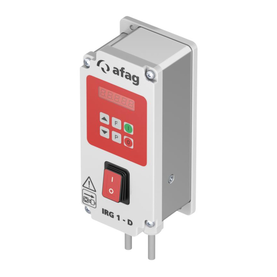
Page 17: Design And Description
2. On/off switch 4. Housing Description of the controller The electronic controller IRG1-D is used for the stepless control of inductive loads such as bowl feeders and linear feeders. The controller operates according to phase-angle control and thus generate a variable output voltage for the drive solenoid. -
Page 18: Installation, Assembly & Setting
M8 4-pol. 4 = Release input Acceleration sensor 1 = +24 V Output 2 = Input 3 = GND 4 = nc Fig. 5 Connection options 18 – 28 Operating Instructions EN ◼ IRG1-D ◼ Date 19.04.2024 ◼ Version 2.0... - Page 19 Power input Output 230V/110V 50/60 Hz 230V Vibratory feeder Fig. 6 Sectional view of the IRG1-D NOTICE Risk of damage to the printed circuit board! Incorrect setting of the slide switches can cause a malfunction or damage to the PCB.
-
Page 20: Operation
General All necessary settings for the vibratory drive are made via the display! Control panel and keyboard Display keypad Fig. 7 Control panel IRG1-D Keys Meaning / Function "I" / "O" Switching the output on and off "F" / "P Change menu items "↑"... -
Page 21: Settings
The internal slide switch must be in the corresponding position. 7.2.6 Setpoint setting Selection: Membrane keypad and/or external setpoint (control current 0(4)... 20 mA) (control voltage 0(2)... 10 V) (alternative). Operating Instructions EN ◼ IRG1-D ◼ Date 19.04.2024 ◼ Version 2.0 21–28... -
Page 22: Full And Half Wave
The smooth start and smooth stop of the output voltage is set under menu C003 with the parameters "/." and "\." (0.1...60 sec). 7.2.9 Release inversion The release inversion is done under menu C003 with parameter "-En. 22 – 28 Operating Instructions EN ◼ IRG1-D ◼ Date 19.04.2024 ◼ Version 2.0... -
Page 23: Fault Elimination
Speed changes from fast to slow and vice versa ▪ Wrong mains voltage solenoid ▪ Check mains voltage Magnet gets hot ▪ Incorrect oscillation frequency ▪ Set oscillation frequency Operating Instructions EN ◼ IRG1-D ◼ Date 19.04.2024 ◼ Version 2.0 23–28... -
Page 24: Maintenance And Repair
▪ Only use trained specialist personnel to carry out the activities. chap. 2 „Safety instructions“ in this Also observe the safety instructions in manual. Maintenance work 9.3.1 Overview Fig. 8 Controller IRG1-D System Interval Maintenance point Maintenance work Remarks [On/Off] Controller Check fuse... -
Page 25: Further Maintenance
Afag for repair within the warranty period. After expiry of the warranty period, the customer may replace or repair defective controllers or wear parts himself or send them to the Afag repair service. Please note that Afag does not assume any warranty for controllers that have... -
Page 26: 10 Decommissioning, Disassembly, Disposal
▪ Electronic parts, electrical scrap, auxiliary and operating materials must be disposed of by approved specialist companies. ▪ Information on proper disposal can be obtained from the responsible local authorities. 26 – 28 Operating Instructions EN ◼ IRG1-D ◼ Date 19.04.2024 ◼ Version 2.0... - Page 27 Operating Instructions EN ◼ IRG1-D ◼ Date 19.04.2024 ◼ Version 2.0 27–28...
- Page 28 28 – 28 Operating Instructions EN ◼ IRG1-D ◼ Date 19.04.2024 ◼ Version 2.0...
Need help?
Do you have a question about the IRG1-D and is the answer not in the manual?
Questions and answers