Advertisement
Quick Links
Advertisement

Subscribe to Our Youtube Channel
Related Manuals for Peak MR06


Summary of Contents for Peak MR06
-
Page 2: Table Of Contents
CONTENTS Product Features and Specifications ............1 Installation Requirement..…………………………...…..…….………………………………………….2 Steps of Installation...………………....…………………......3 Exploded View...……………………………..………….…...….………………………………………….. 10 Operation Instruction..……………………………………..…..…………………………………………..12 Maintenance …………………………………………………………………………………………………….. 14 Trouble Shooting ...………………………………………..…………………………………………….. 15 MR06 Parts List ...……………………………………………..….…………………………………………. 16... -
Page 3: Product Features And Specifications
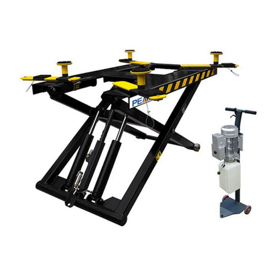
I. PRODUCT FEATURES AND SPECIFICATIONS PORTABLE MID-RISED MODEL MR06 Automatic safety lock: 3 position safety locks, mechanical safety locks release, No ● need of air source. High speed: From 0-1090mm (43”) in just 21 seconds ● Portable design: It is easy to move the unit with the power unit stand ●... -
Page 4: Installation Requirement
II. INSTALLATION REQUIREMENT A. TOOLS REQUIRED Screw Set Grease gun Hook spanner (40~42mm) English Spanner (12″) Pliers Wrench sets : # # # # 、15 、17 、19 Fig. 2 B. POWER SUPPLY The electrical source must be 2.2kw minimum. The source cable size must be 2.5mm²... - Page 5 III. INSTALLATION STEPS A. Check the parts before assembly, make sure all the parts are completed. 1. Packaged lift, Parts box, Power Unit and Power Unit Stand. Move the parts aside, open the outer packing and check the parts according to the shipment parts list (See Fig.
- Page 6 3. Check the parts of the parts bag according to the parts bag list (See Fig. 5) Fig.5 B. Install hydraulic power unit and needle valve (See Fig. 6) Fig. 6...
- Page 7 C. Install oil hose (See Fig. 7) Fig. 7...
- Page 8 D. Install supporting arm 1. Prepare the parts of supporting arms (See Fig. 8) Fig. 8 2. Install supporting arms and pads (See Fig. 9) Fig. 9...
- Page 9 Note: 1. For the safety of operators, the power wiring must contact the floor well. 2. Pay attention to the direction of rotations when using three phase motors. PEAK Single phase motor (See Fig. 10) 1. Connecting the two power supply lines (fire wire L and zero wire N) to terminals of AC contactor marked L1, L2 respectively.
- Page 10 SPX Single phase motor (See Fig. 11) 1.Power supply line (active wire L) connected with wire 4#of control button. 2.Wire 3#of control button connected with wire 6# of motor. 3.Power supply line (neutral wire N) connected with wire 5# of motor. Earth wire 4#...
- Page 11 PEAK three phase motor 1. Circuit diagram (See Fig. 12) Three phase Fig.12 2. Connection Step (See Fig. 13) a. The source wires (L1, L2, L3) are connected with terminals of AC contactor marked L1, L2, L3 respectively. b. Terminals of AC contactor marked L1 are connected with terminals 4# of control button.
-
Page 12: Exploded View
IV. EXPLODED VIEW Model MR06 Fig. 14... - Page 13 CYLINDER Fig.15 SPX power unit 220V,50Hz Fig.16...
- Page 14 PEAK MANUAL POWER UNIT 220V/50HZ/1 phase 380V/50HZ/3 phase Fig.17 SPX Power unit 220V 50Hz single phase(Fig.18) Capacitor Relief valve Protective ring Oil return port Auxiliary Check valve hole Release valve Auxiliary hole Oil outlet Handle for release valve Fig.18...
- Page 15 PEAK Power unit 220V 50Hz single phase (See.Fig19) Capacitor Protective ring Oil return port Oil return port Relief valve Check valve Release valve Throttle valve Oil outlet Handle for release valve Fig.19 PEAK power unit 380V 50Hz Three phase Protective ring...
-
Page 16: Operation Instruction
V. OPERATION INSTRUCTIONS 1. Install the oil hose between oil cylinder and power unit, connect with the power supply wire well. The machine can be ready to use. 2. When lifting vehicle, be sure the center of gravity of vehicle must be in the middle of lift, select the suitable adapters and move the arms to find the support point. -
Page 17: Maintenance
VI. MAINTENANCE SCHEDULE Monthly: 1. Lubricate all moving parts with lubricant (See Fig.22) Fig. 24 2. Check all connectors, bolts and pins to insure proper mounting. 3. Make a visual inspection of all hydraulic hoses/lines for possible wear or leakage. Every six months: 1. -
Page 18: Trouble Shooting
VII. TROUBLE SHOOTING TROUBLE CAUSE REMEDY 1. Button does not work 1. Replace button 2. Wiring connections are not in good 2. Repair all wiring connections condition Motor does not 3. Motor burned out 3. Repair or replace motor 4. Safety Switch is damaged 4. - Page 19 VIII. PARTS LIST FOR MODEL MR06 Note Item Part# Description QTY. (See Fig. 14, Fig.6-7) 640001 Platform 640002A Stackable Adapter Bracket 209052B Stackable Adapter (2.5”) 209051B Stackable Adapter (1.5”) 201046A Rubber Pad Assy. 420138 Socket bolt 209134 Rubber pad 680030C...
- Page 20 Item Part# Description QTY. Note 420097 Straight Fitting 640020 Manual Power Unit 209003 Hex Bolt 209005 Self locking Nut 640021 Power Unit Stand 206006 Washer 201005 Split Pin 640023 Roller Fitting 201020 209119 compensation valve 209060 Straight Fitting For Power Unit 209062 T Fitting Oil Hose...
- Page 21 SPX manual Power Unit 2200V/50HZ/1 phase (See Fig. 16) Item Part# Description QTY. Note Motor 201-1 81400030 Protective Ring 201-2 81400159 Motor Connecting Shaft 201-3 81400063 Valve Body 201-4 81400031 Relief Valve 201-5 81400160 Lock Washer 201-6 81400161 Socket Bolt 201-7 81400162 Inlet Pipe...
- Page 22 PEAK manual Power Unit 220V/50HZ/1 phase (See Fig. 16) Item Part# Description QTY. Note Motor 201A-1 81400048 Protective Ring 201A-2 81400178 AC Contactor 201A-3 81400179 Motor Connecting Shaft 201A-4 81400127 Valve Body 201A-5 81400067 Relief Valve 201A-6 81400106 Throttle Valve...
- Page 23 PEAK manual Power Unit 380V/50HZ/3 phase (See Fig. 16) Item Part# Description QTY. Note Motor 201B-1 81400183 Protective Ring 201B-2 81400178 AC Contactor 201B-3 81400184 Motor Connecting Shaft 201B-4 81400127 Valve Body 201B-5 81400177 Relief Valve 201B-6 81400175 Throttle Valve...
- Page 24 72206401 12/2015...
Need help?
Do you have a question about the MR06 and is the answer not in the manual?
Questions and answers