Table of Contents
Advertisement
Quick Links
Advertisement
Table of Contents

Related Manuals for Peak SML-6


Summary of Contents for Peak SML-6
- Page 1 Original SINGLE POST LIFT Model: SML-6...
-
Page 2: Table Of Contents
CONTENTS Product Features and Specifications ............... 1 Installation Requirement ……………………………………………………….………………...………3 Steps of Installation …...................4 Exploded View ....................14 Test Run ………..................... 24 Operation Instruction .................. 25 Maintenance ....................26 Trouble Shooting ..................27 LIFT DISPOSAL ....................27... -
Page 3: Product Features And Specifications
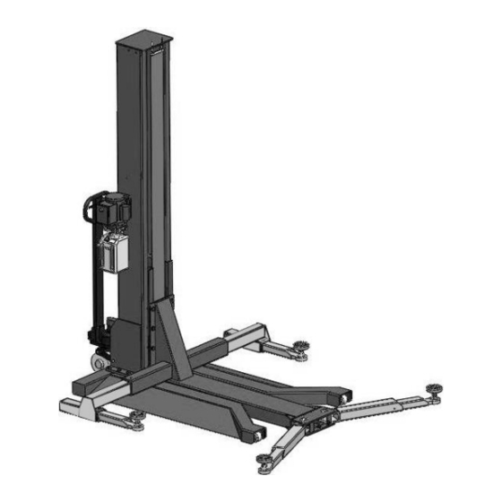
I. PRODUCT FEATURES AND SPECIFICATIONS Fig.1 MOBILE CHAIN-DRIVE SINGLE POST MODEL SML-6 · Compact design. · Hydraulic cylinders, designed and made on ANSI standard, utilizing NOK oil seal in cylinder. · Self-lubricating UHMW Polyethylene sliders and bronze bush. · Single-point safety release, and dual safety design. - Page 4 Arm Swings View 48-1/2” Fig.2...
-
Page 5: Installation Requirement
II. INSTALLATION REQUIREMENT A. TOOLS REQUIRED Screw sets Level Bar Tape Measure(7.5mm) English Spanner(12″) Pliers Socket Head Wrench Wrench set:(10 # # # # 、13 、14 、12 # # # 、19 、24 、30 Fig.3... -
Page 6: Steps Of Installation
B. STORAGE AND INSTALLATION REQUIRMENT Keep or install the equipment in shaded, normal temperature, dry and ventilated environment. C. POWER SUPPLY The electrical source must be 2HP minimum. The source cable size must be 2.5mm² . III. STEPS OF INSTALLATION A. - Page 7 2. Take off the packaging on the machine Take off the packing rack. 3. Move aside the parts and check the parts according to the shipment parts list (See Fig.5 & 6) Fig.5 Shipment list Parts Box (42) Fig.6 4. Check the parts of the parts bag according to the parts bag list (See Fig. 7) Fig.7...
- Page 8 C. Lay the base flat to the ground, confirm installation place according to the ground state, the main purpose is to save space. (See Fig.8) Fig.8 D. Install column and lift platform 1.Lay the column flat to the ground. (See Fig.9) Fig.9 Fig.9 2.Connecting oil hose of cylinder.
- Page 9 3.Fix column to the base plate. (See Fig.11) 4.Fix lifting platform to carriage. (See Fig.12) Fig.11 Fig.12 Fig.
- Page 10 E. Install cover of the safety device, retainer and protective cover (See Fig.13) After install the retainer, tighten slightly with M6*8 cup-head bolt. Install safety device as below Fig.13...
- Page 11 F. Install power unit and oil hoses (See Fig.14) Note: Tighten the oil hose fitting and power unit fitting to avoid oil leakage; Pay attention to the direction of power unit fitting. Tighter the screw with 19# wrench set after installing power unit fitting.
- Page 12 G. Install plastic cover (See Fig.15) Support plate for chain clip 链夹支撑板 Plastic baffle across 塑胶挡板从此处穿过 from here Fig.15 H. Connect the power source according to the data on plate of power unit Note: For the safety of operators, the power wiring must have a good ground connection. Single phase motor (See Fig.
- Page 13 I. Install lifting arms Lowing the carriages down to the lowest position, fix cup head bolt M8*16 (see Fig.17) then tighten the screw (See Fig. 18). Hex screw M8*16 Fig.17 Tighten the screw with wrench Fig.18...
- Page 14 J. Install wheel assembly 1. First tighten the wheel assembly fixed square pipe by socket bolt with lock washer φ12 (Fig.19). Put the wheel assembly into the fixed square pipe then tighten it. (Fig.20), Fig.20 Fig.19 2. Insert the wheel assembly connecting board and fixed by elastic latch (Fig.21). Elastic Latch Fixing Pin Fig.21...
- Page 15 K. Tighten all the hydraulic fittings, and fill the reservoir with hydraulic oil. Note: In consideration of Hydraulic Power Unit’s durability and keep the equipment running in the perfect condition, please use Hydraulic Oil 46#. L. Using level to measure and adjust the column to be vertical (Fig.23). Use level to measure the column by front and side to make sure the column is vertical...
-
Page 16: Exploded View
Ⅳ EXPLOEDED VIEW Model: SML-6 10~13 16~18 22~24 27 28 59 58 57 56 51~53 Fig.24... - Page 17 PARTS LIST FOR SML-6 Item Part# Description QTY. Note 10209009 Cup Head Bold M6*8 10209008 Safety Cover 11206002 Safety Pin 10209007 Safety Spring 11203002 Power Side Safety Device 11203013 Coupling 10209012 Elastic Pin 10420049 Split Pin 10101028 Wheel Assembly 10217013...
- Page 18 Item Part# Description QTY. Note 10203117 Hook with adjustment Screw 10101007 Chain 10207008 Chain Pulley seat assy. 10207010 Cylinder 10201010A Chain Connector 10102501 Parts Box 10683018 Springφ18*φ11*70 11101039 Roller shaft 41080221 Bearing 11101038 Roller 11101675 Roller shaft limit block 10207021 Socket Bolt M6*12 10203054 Rubber Pad Assy.
- Page 19 Rubber Pad Assy.(10203054)Exploded View: QTY. Item Part# Description Fig. 25 10420043 Socket Bolt M8*20 10203043 Double screwed rubber Pads 11203026 Rubber Pad Frame Assy 10201060 O Ring 11203025 Adjusting Rod 10203041 Lock washer 11203024 Revolving Shaft 10203042 Lock Washer 4.2 Lifting Arm (outer)(10101033)Exploded View: Fig.
- Page 20 4.3 Lifting Arm (Inner Left)(10102029)Exploded View: QTY. Item Part# Description 1021149 Cup Head Bolt M8*12 11102610 Outer Arm (Inner-left) 11203101 Lifting Arm (inner) Fig. 27 4.4 Lifting Arm (Inner Right)(10102028)Exploded View: QTY. Item Part# Description 1021149 Cup Head Bolt M8*12 11102612 Outer Arm (Inner-right) 11203101...
- Page 21 4.6 Cylinder (10207010)Exploded View: Fig. 30 QTY. Note Item Part# Description 11207027 Piston Rod 11207028 Piston 10206069 O-Ring 10620053 Support Ring 10620054 Y-Ring 10630027 O-ring 10206071 Hex Nut 11207029 Piston rod adjusting sleeve 10217078 Dust Ring 10520058 O-Ring 11207030 Head Cap 10201034 Bleeding Plug 10207031...
- Page 22 071103 4.7 Manual Power Unit ( )Exploded View: 110V/60HZ/1 Phase Manual Fig. 31...
- Page 23 PARTS LIST FOR MANUAL POWER UNIT (071103) ITEM Part# Description QTY. Note Rubber pad 81400180 Start capacitor 81400130 Run capacitor 81400088 Cup Head Bolt with Washer 10420148 Cover of capacitor 81400066 Motor connecting shaft 81400363 Manifold block 81400362 Lock Wash 10209149 Iron Plug 81400276...
- Page 24 071104 4.8 Manual Power Unit ( )Exploded View: 220V/60HZ/1 Phase Manual Fig. 32...
- Page 25 PARTS LIST FOR MANUAL POWER UNIT (071104) ITEM Part# Description QTY. Note Rubber pad 81400180 Start capacitor 81400130 Run capacitor 81400088 Cup Head Bolt with Washer 10420148 Cover of capacitor 81400066 Motor connecting shaft 81400363 Manifold block 090101 Lock Wash 10209149 Iron Plug 81400276...
-
Page 26: Test Run
Illustration of hydraulic valve for hydraulic power unit Up Button Oil return port Relief valve Release Valve Oil output port Throttle Handle for valve release valve Check Valve Fig. 33 V. TEST RUN 1. Adjust the lower speed (Fig.34) You can adjust the lower speed of the lift if needing: Turn the Throttle Valve in clockwise direction to decrease the lower speed, or increase the speed in counterclockwise direction. -
Page 27: Operation Instruction
2. Test with load After finishing the above adjustment, test running the lift with load. Lift the lift in low position for several times first, make sure the lift can rise and lower without improper. And then test run the lift to top position completely. If there are anything improper, repeat the above adjustment. -
Page 28: Maintenance
8. Slowly lift the lift. Make sure that the car is in a balanced state, then lift the car to the required height and release the UP button 9. Press the release handle of the power unit and lower the lift to the safety lock position. Only after confirming that the safety device is in a normal working state then the car can be maintained. -
Page 29: Trouble Shooting
VIII. TROUBLE SHOOTING TROUBLE CAUSE REMEDY 1.Start Button does not work 1. Replace button 2.Wiring connections are not in good 2. Repair all wiring connection condition Motor does 3. AC contractor burned out 3. Repair or replace contractor not run 4. - Page 30 No:72115105 Date:2019/11...
Need help?
Do you have a question about the SML-6 and is the answer not in the manual?
Questions and answers