TABLE OF CONTENTS INTRODUCTION ......................................... 6 Copyright .......................................... 6 Copyright notice ......................................6 Trademarks ........................................6 Warranty ........................................... 6 Environmental information ................................... 6 Recycling of end-of-life products ..............................6 Warranty registration ....................................7 Getting started ......................................7 Contents ........................................... 7 Icons ............................................
Page 3
Option Connection Mode List ................................97 SPARES PART LIST ......................................98 PARTS REPLACEMENT RECOMMENDATION ..........................99 AVANSIA PRINT CALIBRATION ................................100 Test Pattern X: Print Position Adjustment ..........................101 Test Pattern Y: Print Density ................................102 Test Pattern Z: Print Uniformity ..............................103 Print Test U: Vertical color shifting ...............................
All the information contained in this document is subject to change without prior notice. Evolis cannot be held liable for any errors that may be found in this manual, or for any loss or damage arising accidentally or as a result of dissemination or use of this manual.
As with all Evolis products, a great deal of care has been taken over this manual. Should you find an error, however, please let us know by emailing us at info@evolis.com.
Evolis dealer, who will tell you the procedure to follow. Evolis takes great care over the quality of its packaging, and we ask that you keep this packaging somewhere clean and dry.
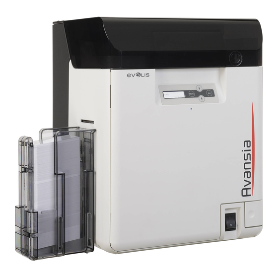
DESCRIPTION OF THE PRINTER Top cover Control Panel Front cover Front cover button On-off switch Card output hopper Card ejection slot Card input feeder 2. Feeding roller 3. Trapdoor cover 4. Card case lock Reject slot Peripheral USB socket Ethernet socket (Lan cable port) Port for enhancing function Security cable slot Power cable socket...
Page 10
Card feeding wheel 2. Reverse feeding wheel 3. Cleaning roller 4. Cleaning tape cassette 5. Reverse wheel 6. Ink ribbon cassette 7. Transfer film cassette 8. Key holder Connecting the output hopper Connecting the reject box Service Manual_AVA1_ENG-20220922_I...
Under no circumstances should you connect the USB data cable before installation of the printer driver is complete. Refer to the section on printer driver installation available in the Avansia User Guide for further details and follow the instructions carefully.
GENERAL OUTLINE Overall Explanation Basic specifications For the basic specifications of this printer, refer to the “User Guide Avansia”. Mechanism components and functions This printer consists of a primary transferring unit, secondary transferring unit, de-curling unit, card transferring unit, card feeder unit, cleaning unit, flip section, card stacker unit, and a unit for mounting optional parts.
Page 13
Primary transferring unit • The primary transferring unit uses a 600-dpi thermal line scan head, which is installed near the inked ribbon. It transfers ink from the inked ribbon to the transfer film while moving the inked ribbon and transfer film. This mechanism is called thermal transferring.
Cassette Handling Good Practices Avansia cassettes must be handled with care because cassettes play a very important role in print and lamination quality. Cassettes have reference posts that must remain in original position: Otherwise, when a reference post is torn, it can create used roll winding issues: badly spun used roll will pull ribbon/film unevenly which will make film/ribbon crease.
Image printing process Primary Transfer Feed Roller (Platen Roller) Overview Presses the Ink Ribbon and Transfer Film against the Printhead. Control description The up and down operation is controlled by the Platen Lift Motor (DM5). In addition to the Primary Transfer Feed Roller (Platen Roller), the Platen Lift Motor (DM5) also controls the up and down movement of the Film Nip Roller.
Ink Ribbon Overview Control description Panel configuration: There are two types, a YMCK four panel configuration and a YMCKK five panel configuration. Regarding position control of the Ink Ribbon, resolution is calculated by measuring the number of clock occurrences from the Ribbon Feed Length Sensor (Wind Up Axis and Supply Axis, SN10 and SN11 - respectively), generated at the time when it passes through the K panel detected by the Ribbon Beginning Sensor (SN9).
Initial Operation of Ink Ribbon and Transfer Film Overview Control description The RFID PCB makes initial communication with Main board and ID-key to acquire the type and remaining amount information of ink ribbon. When ink ribbon is used by initial operation, the remaining amount information of ink ribbon is updated.
Heat Roller Overview Primarily transferred film is transferred to the card using a Heat Roller. Temperature control The Transfer Film on which print data is formed and the leading edge of the card are pressed by a Heat Roller heated to a required temperature in advance and Card Feed Roller 3. The card and the Transfer Film are fed until the trailing edge of the card passes through the Heat Roller, thereby transferring print data formed on the Transfer Film to the card.
Feeding & Transport process Cards [1] set in the card cassette are 2. Dust adhered to the card is removed by the supplied one at a time by the Supply Roller Cleaning Roller [1]. [2]. 3. The cleaned card is fed to the Reverse 4.
Page 20
7. The card is fed to the Decurl Assembly [3] by 8. In case of printing on the second side, the Card Feed Rollers 4 [1] and 5 [2]. If there is a card is fed to the Reverse Assembly [1]. decurl setting, the Decurl Plate [4] of the Decurl Assembly descends and corrects the curling of the card.
Page 21
11. The card is fed by the Card Feed Roller 3 [1], 12. The card is fed to the Decurl Assembly [3] by and the second side is printed. Card Feed Rollers 4 [1] and 5 [2]. If there is a decurl setting, the Decurl Plate [4] of the Decurl Assembly descends and corrects the curling of the card.
USING THE OPERATION PANEL Users can manipulate the operation panel, which is installed on the top of the printer, to display printer status, set printer functions (e.g., card reprinting), re-adjust the printer, and check printer operation. Description Menu Key Keys LCD Panel SET Key LED Status...
"printing" and "error". Normal mode is the default when the printer is turned on. For functions and operation, see “Avansia User Guide". User mode To switch from Normal Mode to User mode: Set printer functions, such as card discharging units.
Switching Menus Service mode and option connection mode have a tree structure classified according to the contents of each menu. Refer to the service mode list or option connection mode list for menu configuration and classification. Switching menus of the same level •...
User Mode List Menu Submenu Setting or Status (display) Possible values Printer Info Card count Reset (YES / NO) Total Count Status Ribbon Capacity Status Film capacity Status Version Base Version Display Main Version Display FW version Printer S/N Display printer SN Printhead S/N Display printhead SN Magnetic Encoder...
Page 26
Menu Submenu Setting or Status (display) Possible values Card Type Card Setup PVC 30mil/0.76, PET-G 30mil, PET 30mil/0.76, PC 30mil/0.76, Composite PVC / CARD1 / CARD2 / CARD3 Decurl (Front) 0 to 15 Decurl (Back) 0 to 15 Std card exit LEFT SIDE / RIGHT SIDE Err card exit RIGHT SIDE / LEFT SIDE...
Error Log Check (error log check menu)] This menu checks the frequency and history of error occurrence. Error Log Check > Error Rate Overview Display of the error occurrence rate. Detail To display the error occurrence rate. 2nd line display: [aa/bbbbbb cc.cc%] •...
ERROR CODE LIST ERROR Common ERROR MESSAGE DESCRIPTION CODE description 01-01 Card empty error (during card print reception) FEEDER EMPTY 01-02 Card empty error (during standby) 04-01 Front cover open 05-01 COVER OPEN Front cover open during initialization) 06-01 Front cover open (during printing) LOW TEMPERATURE 0D-01 Low environmental temperature error (<...
Page 32
1D-09 Abnormal index mark transfer position for hologram film 1D-0A Transfer film position error (non-detection) 1E-05 REMOVE FILM Transfer film installation detection error (during cleaning) 20-XX 21-XX REMOVE CARD FLIP Feeder to flip over card jam error 22-XX 23-XX 24-XX 25-XX FLIP CARD JAM Flip over card jam...
Page 33
64-01 Thermistor temperature error 64-11 CALL TECH SUPPORT Print head thermistor temperature error 64-12 64-21 64-22 Thermistor temperature error 64-31 64-FF Board error (AD converter) 65-XX Heat roller temperature error 67-XX RIBBON KEY ERROR ID-key communication error 68-XX RIBBON KEY EMPTY ID-key empty detection 69-XX RIBBON DEVICE...
ERROR CODE DETAILS Code 01-01-to 3F-XX Error Code Item Description 01-01 Error Message Feeder empty Outline Card empty error (during card print reception) Detection Description The printer detected absence of cards in the card case during card print reception. Remedy [Related parts] Harnesses from the Card Sensor (SN1) to the Main board •...
Page 36
Error Code Item Description 06-01 Error message Cover open Outline Front access cover open error (during printing) 06-01 Detection Description The printer detected the front access cover open during printing. Remedy [Related parts] • Harnesses from the Front Cover Switch (MS1) to the Main board •...
Page 37
Error Code Item Description 11-01 Remedy [Related parts] 11-02 • Ink Ribbon Cassette • Harnesses from the Ribbon Feed Length Sensor (Wind Up Axis) (SN10) to the Main board Harnesses from the Ribbon Wind Up Motor (DM1) to the Main board •...
Page 38
Error Code Item Description 13-01 Remedy [Related parts] 13-02 • Ink Ribbon Cassette 13-03 • Harnesses from the Ribbon Beginning Sensor (SN9) to the Main board Ribbon Beginning Sensor (SN9) • Main board • [Remedy] Check the following items of the ink ribbon cassette. ⋅...
Page 39
Error Code Item Description 13-09 Remedy [Related parts] • Ink Ribbon Cassette • Harnesses from the Ribbon Beginning Sensor (SN9) to the Main board Ribbon Beginning Sensor (SN9) • Main board • [Remedy] Check the following items of the ink ribbon cassette. ⋅...
Page 40
Error Code Item Description 14-XX Remedy [Related parts] • Ink Ribbon Cassette • Harnesses from the Ribbon Beginning Sensor (SN9) to the Main board Ribbon Beginning Sensor (SN9) • Main board • [Remedy] Check the following items of the ink ribbon cassette. ⋅...
Page 41
Error Code Item Description 18-01 Error Message No Film Outline Transfer film empty error (during initialization) Detection Description The printer detected the transfer film empty during initialization. Remedy [Related parts] • Harnesses from the Film Beginning Sensor 2 (SN13) to the Main board Film Beginning Sensor 2 (SN13) •...
Page 42
Error Code Item Description 19-03 Error Message Film Wind up. 19-04 Outline Transfer film wind up speed error (supply axis) Detection The printer detected the wind-up speed error of the transfer film. Description Remedy [Related parts] Transfer Film Cassette • Harnesses from the Film Feed Length Sensor (Supply Axis) (SN15) to •...
Page 43
Error Code Item Description 1C-XX Error Message Invalid Film Outline Transfer film feed operation timeout error Detection Description The printer detected the feed operation timeout of the transfer film. Remedy [Related parts] Transfer Film Cassette • • Harnesses from the Film Beginning Sensor 1 (SN12) to the Main board •...
Page 44
Error Code Item Description 1D-07 Error Message Invalid Film Outline Transfer film empty redetection error Detection After the printer detected the transfer film empty, it detected empty after Description initialization again. Remedy [Related parts] Transfer Film Cassette • Harnesses from the Film Beginning Sensor 1 (SN12) to the Main board •...
Page 45
Error Code Item Description 1D-0A Error Message Invalid Film Outline Transfer film use position error (non-detection) Detection The printer could not detect the transfer film use position. Description 1D-0A Remedy [Related parts] Transfer Film Cassette • Harnesses from the Film Beginning Sensor 1 (SN12) to the Main board •...
Page 46
21-XX Error Message Remove Card: flip Outline Reverse assembly card jam error Detection Description The printer detected a card jam at the Card Sensor (Cleaning Assembly Inlet) (SN24) and the Card Sensor (Cleaning Assembly Outlet) (SN2). Remedy [Related parts] Harnesses from the Card Sensor (Cleaning Assembly Inlet) (SN24) to the Main •...
Page 47
24-XX Error Message Flip Card Jam Outline Reverse assembly card jam error Detection Description The printer detected a card jam at the Card Sensor (SN26) Remedy Check that there are no incorrect settings for the “IC R/W1” connection in “Option Mode”. [Related parts] Harnesses from the Card Sensor (Reverse Assembly Outlet) 26) to...
Page 48
the Main board • Harnesses from the Card Feed Motor (Reverse Assembly) (PM2) to the Main board Card Sensor (Reverse Assembly Outlet) (SN20) • Card Feed Motor (Reverse Assembly) (PM2) • Main board • [Remedy] Check if a card is jammed at the designated position Check the reaction of the Card Sensor (Reverse Assembly Outlet) (SN20) in the sensor check mode (page 27).
Page 49
Error code Item Description 28-XX Error Message Flip Card Jam Outline Reverse assembly card jam error Detection Description The printer detected a card jam in the reverse assembly without the cards on the card sensors (SN2/3/23/24). Remedy [Related parts] Harnesses from the Card Sensor (Cleaning Assembly Outlet) (SN2) to •...
Page 50
Error Code Item Description 2B-XX Error Message Remove Card: mag Outline Reverse assembly card jam error Detection Description The printer detected multiple cards at the card sensors in the reverse assembly. Remedy [Related parts] Harnesses from the Card Sensor (Cleaning Assembly Outlet) (SN2) to •...
Page 51
Error Code Item Description 31-XX Error Message Card Jam Print Outline Secondary transfer assembly card jam error Detection Description The printer detected a card jam at the Card Sensor (Reverse Assembly Outlet) ) and the Card Edging Sensor (Secondary Transfer Assembly) (SN5). Remedy [Related parts] •...
Page 52
Error Code Item Description 34-XX Error Message Card Jam Print Outline Secondary transfer assembly card jam error Detection Description The printer detected a card jam at the Card Edging Sensor (Secondary Transfer Assembly) ( ) and the Card Sensor (Ejection Assembly Left) ( Remedy [Related parts] Harnesses from the Card Edging Sensor (Secondary Transfer...
Page 53
Error Code Item Description 36-XX Error Message Remove Card: prtr Outline Secondary transfer assembly card jam error (multiple cards) Detection Description The printer detected multiple cards in the secondary transfer assembly. Remedy [Related parts] • Harnesses from the Card Sensor (Reverse Assembly Outlet) (SN3) to the Main board Harnesses from the Card Edging Sensor (Secondary Transfer •...
Page 54
Error Code Item Description 39-XX Error Message Remove Card: fdr Outline Card supply assembly card jam error Detection Description The printer detected a card jam at the Card Sensor (Cleaning Assembly Inlet) (SN24) and the Card Sensor (Cleaning Assembly Outlet) (SN2). Remedy [Related parts] Harnesses from the Card Sensor (Cleaning Assembly Inlet) (SN24) to...
Page 55
Error Code Item Description 3C-XX Error Message Remove Card: fdr Outline Card double feeding jam error of the card supply assembly Detection Description The printer detected the card double feeding jam at the Card Sensor (Cleaning Assembly Outlet) (SN2) during card feeding. Remedy [Related parts] •...
Page 56
Error Code Item Description 3F-XX Error Message Remove Card: fdr Outline Card supply assembly card jam error (multiple cards) Detection Description The printer detected multiple cards in the card supply assembly. Remedy [Related parts] Harnesses from the Card Sensor (Cleaning Assembly Outlet) ( ) to •...
Code 40-XX to BF-01 Error Code Item Description 40-XX Error Message Call Tech Support Outline Reverse assembly rotation operation error Detection Description Rotation operation error of the reverse assembly was detected. Remedy [Related parts] Harnesses from the Reverse Assembly Position Sensor 1 (SN7) to the •...
Page 58
Error Code Item Description 43-XX Error Message Call Tech Support Outline Decurl assembly lift operation error Detection Description Lift operation error of the decurl assembly was detected. Remedy [Related parts] • Harnesses from the Decurl Assembly Position Sensor (SN19) to the Main board Harnesses from the Decurl Assembly Drive Motor (DM7) to the Main •...
Page 59
Error Code Item Description 54-XX Error Message Call Tech Support Outline Magnetic R/W unit hardware error Detection Description Hardware error of the Magnetic R/W unit was detected. Remedy [Related parts] • Harnesses from the Magnetic R/W Unit to the Main board Magnetic R/W Unit •...
Page 60
Error Code Item Description 62-03 Error Message Call Tech Support Outline Fan operation error Detection Description Operation error of the heat roller cooling fan was detected. Remedy [Related parts] • Harnesses from the Heat Roller Cooling Fan (FAN3) to the Main board Heat Roller Cooling Fan (FAN3) •...
Page 61
Error code Item Description 64-01 Error Message Call Tech Support Outline Thermistor temperature error Detection Description The heat roller thermistor (TM2) detected a temperature outside of the controlled range. Remedy [Related parts] • Harnesses from the Heat Roller Thermistor (TM2) to the Main board Heat Roller Thermistor (TM2) (Unit of replacement: Heat Roller) •...
Page 62
Error Code Item Description 65-XX Remedy [Related parts] • Harnesses from the Heat Roller to the Main board • Heat Roller • Main board [Remedy] Check/replace the related harness/cable, connector and parts. 67-XX Error Message Ribbon Key Err Outline ID-key communication error Detection Description ID-key communication is in an abnormal condition.
Page 63
Error Code Item Description 6E-XX Error Message Call Tech Support Outline Board error (FPGA) Detection Description Access to the FPGA failed. Remedy [Related parts] • Main board [Remedy] Restart the PC and printer. Reinstall the firmware. Check/replace the related parts. 6F-XX Error Message Firmw.
Page 64
Error code Item Description BE-XX Error Message Printhead error Outline Printhead data download error Detection Description Resistance data of the printhead has been not downloaded. Remedy [Related parts] • Main board [Remedy] Download the head resistance data. If this error occurs routinely, contact to the sales company. BF-01 Error Message Download Error...
EXPLODED VIEW Drawing 1 LCD FOR OPERATION PANEL LCD MAIN BOARD CP011782 CP011689 REJECT BOX CI010222 TOP BLACK COVER S10203 OUTPUT CARD HOPPER S10202 REAR TOP COVER CP011784 FILTER COVER CP011789 REAR BLACK COVER S10204 DUST FILTER CP011777 Service Manual_AVA1_ENG-20220922_I...
Page 66
Drawing 2 FRONT SIDE COVER : LEFT CP011787 FRONT COVER CP013456 REAR SIDE COVER : LEFT CP011785 FRONT SIDE COVER : RIGHT CP012516 REAR SIDE COVER : RIGHT CP011786 Service Manual_AVA1_ENG-20220922_I...
Page 67
Drawing 3 FEEDER FOAM CP011776 FACE COVER CP011783 CARD FEEDER S10201 TRANSFER FILM CASSETTE S10199 INK RIBBON CASSETTE S10200 Service Manual_AVA1_ENG-20220922_I...
SENSORS / MOTORS/ FANS/SWITCHES FONCTION LIST Part Part Description Location Function Card sensor Card feed (feeder) Detection of card empty Card Sensor (Cleaning Detection of the card (flip: cleaning Assembly Outlet) position) Card Sensor (Reverse Detection of the card (Flip section Card feed (flip turn) Assembly Outlet) position)
Page 80
Part Part Description Location Function Power Switch Power on/power off Chassis Heat Roller thermistor Detection of temperature (Heat roller) Inner air thermistor Detection of temperature (Inside air) Else Outer air thermistor Detection of temperature (Outside air) Printhead thermistor Detection of temperature (Thermal head) PCB1 Main board Chassis...
SENSOR CHECK Sensor Check > SN01-SN10 Overview Level indications for sensors (SN1 - SN10) Detail Level indications for sensors (SN1 - SN10) Use Case At error occurrence Adj/Set/Operate Select the item, and then press SET key. Meth od Display/Adj/Set The sensor level is displayed on the 2nd line of the LCD in turn from the left end (bit9).
Page 82
Sensor Check > SN21-SN26 The sensor level is displayed on the 2nd line of the LCD in turn from Display/Adj/Set the left end. Range Parts Name Status [Not used] SN21 1: Block light [Not used] SN22 1: Block light Card Sensor (Ejection Assembly SN23 1: Block light Right)
ACTION CHECK PM1: Card Action Check > PM1: Card > PM1: Overview Operation check of the Card Supply Motor (PM1) Forward To operate the Card Supply Motor (PM1) for the specified period of Detail time (1 to 20 seconds) to the feed direction. Use Case Checking the operation Adj/Set/Operate...
PM3: Turn Action Check > PM3: Turn > PM3: Overview Operation check of the Reverse Assembly Rotation Motor (PM3) Forward (counterclockwise) To operate the Reverse Assembly Rotation Motor (PM3) for the Detail specified period of time (1 to 20 seconds) to the counterclockwise direction.
HB2: Film Action Check > HB2 : Film > Overview HB2: Operation check of the Film Feed Motor (HB2) (feed direction) Forward To operate the Film Feed Motor (HB2) for the specified period of time Detail (1 to 20 seconds) to the feed direction. Use Case Checking the operation Adj/Set/Operate...
DM1&DM2: Ink Action Check > DM1&DM2 : Ink > Low speed operation check of the Ribbon Wind Up Motor Low: Overview (DM1)/Ribbon Supply Motor (DM2) (feed direction) Forward To operate the Ribbon Wind Up Motor (DM1) and Ribbon Supply Detail Motor (DM2) for the specified period of time (1 to 20 seconds) to the feed direction.
DM3&DM4: Film Action Check > DM3&DM4: Film > Low speed operation check of the Film Wind Up Motor Low: Overview (DM3)/Ribbon Film Supply Motor- Low: Forward Overview Low Forward speed operation check of the Film Wind Up Motor (DM3)/ Ribbon Film Supply Motor (DM4) (feed direction) To operate the Film Wind Up Motor (DM3) and Ribbon Film Detail...
DM5: Head Action Check > DM5: Head > DM5: Up Overview Operation check of the Platen Lift Motor (DM5) (move up) Detail To operate the Platen Lift Motor (DM5) for the specified period of time (1 to 20 seconds). The nip mechanism of the printhead and transfer film feed roller is moved to the upper position.
DM6: Heat Action Check > DM6: Heat > DM6: Up Overview Operation check of the Heat Roller Lift Motor (DM6) (move up) Detail To operate the Heat Roller Lift Motor (DM6) for the specified period of time (1 to 20 seconds). The nip mechanism of the heat roller and stripping shaft is moved to the upper position.
Card Pass Test Action Check > Card Pass Test > Print Overview Specification of the number of the card feed operation Number Detail To specify the number of the card feed operation. Use Case Checking the operation Adj/Set/Operate Enter the setting value. Meth od Press the SET key, and then confirm the setting value.
Error Log Check > Error Overview Display of the frequency of every error Code Detail To display the frequency of every error. 2nd line display: [GG-GG HH/II] (when selecting error code) Rate GG-GG: Error codes and detailed codes (up to 99 items from the latest) HH: Number of occurrences of the same error code II: Total number of errors stored in the log...
Page 92
Printer Setup > Parallel Print Overview ON/OFF of the parallel process function for multiple cards Detail To set ON/OFF of the parallel process function for multiple cards. ON: Perform the parallel processing (continuous printing). Print up to 2 cards at once through parallel processing in the printer. OFF: Do not perform the parallel processing (prints one card at a time).
Page 93
Printer Setup > Parallel Print Overview ON/OFF of the parallel process function for multiple cards Detail To set ON/OFF of the parallel process function for multiple cards. ON: Perform the parallel processing (continuous printing). Print up to 2 cards at once through parallel processing in the printer. OFF: Do not perform the parallel processing (prints one card at a time).
Revision Check Revision Check > Revision Overview Display of the revision of the printer configuration (8-digit) Adj/Set/Ope N/A (Display only) rate Method Rbn Back Overview Set of the duty of the Ribbon Supply Motor (DM2) at the primary Tension transfer Detail Set the duty of the Ribbon Supply Motor (DM2) at the primary transfer.
Revision Check > Revision Overview Display of the revision of the printer configuration (8-digit) Adj/Set/Ope N/A (Display only) rate Method FilmTension(1st Overview Set of the duty of the Film Wind Up Motor (DM3) and Ribbon Wind Up Motor (DM1) Detail Set the duty of the Film Wind Up Motor (DM3) and Ribbon Wind Up Motor (DM1).
Page 96
Card Setup > Card Feed Overview Set of the card supply source Detail To set the card supply source. Adj/Set/Operate Select the setting value. Meth- od Press the SET key, and then confirm the setting value. Caution The following movement is not applied. Print of the test print in the service mode •...
Option Connection Mode List Level 1 Level 2 Level 3 Level 4 Default Value Display/Adj/ Overview Set Range Magnetic Connection Display of the version and Encoder specifications of magnetic R/W unit connected Coercivity LOW (Lo-Co) LOW (Lo-Co) Set of the coercive force HIGH (Hi-Co) when writing Encode Posi tion1...
SPARES PART LIST Product Product Description Step Page Code S10143 PRINT HEAD S10195 MAIN BOARD S10196 POWER SUPPLY S10197 CLEANING ROLLER STATION S10198 CLEANING TAPE CASSETTE S10199 TRANSFER FILM CASSETTE S10200 INK RIBBON CASSETTE S10201 CARD FEEDER S10202 OUTPUT CARD HOPPER S10203 TOP BLACK COVER S10204...
Product Product Description Step Page Code CP011978 DECURL SPRING CP010901 BOARD RFID CP013577 BUSHING Ø6 Ø10 LG6 WITH FLATS CP013456 FRONT COVER CP013659 ROLLER: FILM CP013457 ROLLER: PRINT PLATEN • * = Replacement procedure not available PARTS REPLACEMENT RECOMMENDATION Product code Name Advice of replacement CP013577...
In case of part replacement (Mainboard, Print Head, HRU, …)), Avansia printer will require calibration, hence modification of some print settings. To do so, we use Test pattern cards from Avansia firmware. We recommend the use of test pattern cards hence to set Avansia printers in the following order: Test Pattern X: Print position Adjustment 2.
Test Pattern X: Print Position Adjustment The following card can be printed from LCD menu: Adjustment >> Position >> Print Test X. This card is used to check the following: A. VTC (top and bottom) and HRZ (left and right) values measured on printed card should be the same, each ~ equal to 2mm.
Test Pattern Y: Print Density To obtain lighter or darker printing, please use Brightness/Contrast/Saturation settings from the driver (page )instead of modifying densities. The following card can be printed from LCD menu: Adjustment >> Density >> Print Test Y. In the following array, each different printed area from the card has been identified: This card is used to check the following: A.
Test Pattern Z: Print Uniformity The following card can be printed from LCD menu: Adjustment >> Position >> Print Test Z. This card is used to check printing uniformity. Color density must be consistent on the whole card. Adjustment >> Density >> YMC | K Adjustment >>...
Print Test U: Vertical color shifting The following card can be printed from LCD menu: Adjustment >> Position >> Print Test U. This card is used to check vertical color shifting. Here is how to use it. Printed card shows 3 columns of lines printed with each panel in order to detect shifting from a panel to another.
Print Test D: Horizontal color shifting The following card can be printed from LCD menu: Adjustment >> Position >> Color Shift HRZ >> Shift HRZ Front >> Print Test D. This card is used to check vertical color shifting. Here is how to use it. Goal of this card is to check the 6 areas with parallel lines printed in different colors (hence with different panels).
Page 106
Same settings exist for both card side Adjustment >> Position >> Color Shift HRZ >> Shift HRZ Back >> Print Test D-B. Each side should be set by application of the following steps. Note that exists an auto color shifting adjustment (Image Setup >> Color Shifting). It is advised to start calibration by using this option, hence set each manual color shifting option to 0.
Test Pattern B: Edge line or faded line detection, Uniformity, Density The following card can be printed from LCD menu: Adjustment >> Wrinkle >> Adjust Wrinkle >> Print Test This card can be used to detect wrinkle issue as it is more prone to generate the issue. Because of the black background, this design can be used to detect/fix edge line issue and/or faded line issue.
REPLACEMENT PROCEDURES These procedures describe how to replace most spare parts. In general, only dismantling is described. Unless otherwise indicated, reassembling should be carried out by reversing the steps. The replacement procedures for certain spare parts may not be presented here, due to the simplicity of dismantling.
Step 1 – REAR BLACK COVER – S10204 Remove the four screws. Remove the six screws. Put the new rear black cover back and carry out the steps in reverse. Service Manual_AVA1_ENG-20220922_I...
Step 2 –REAR TOP COVER – CP011784 Remove the four screws. Remove the two screws. Service Manual_AVA1_ENG-20220922_I...
Page 112
Put the new rear black cover back and carry out the steps in reverse. Check that it is clipped in correctly on both sides. Service Manual_AVA1_ENG-20220922_I...
Step 3 – REAR SIDE COVER - LEFT AND RIGHT – CP011785 – CP011786 Carry out Step 1-1 to Step 1-2 (page 110). 2. Put the new rear side cover (left or right) back in place and put the screws back. 3.
Step 4 – FRONT SIDE COVER: RIGHT – CP011787 Remove the four screws. 2. Open the top cover (a) and remove the card feeder (b). Service Manual_AVA1_ENG-20220922_I...
Page 115
3. Open the front cover (a) and the trapdoor cover (b). 4. Remove the two screws and lift the left front side cover to remove it. 5. Carry out the steps in reverse. Service Manual_AVA1_ENG-20220922_I...
Step 5 – FRONT SIDE COVER: RIGHT– CP012516 Carry out step 9-1 to step 9-5 (page 130). 2. Remove the two black screws. 3. Remove the two screws of the front side cover and open it. Service Manual_AVA1_ENG-20220922_I...
Page 117
4. Rear side, remove the two screws. 5. Open the cables holder. Service Manual_AVA1_ENG-20220922_I...
Page 118
6. Move the hinge outwards 7. Remove the two screws. Service Manual_AVA1_ENG-20220922_I...
Page 119
8. Lift the metal plate to the left. 9. Disengage it from the front side cover. Service Manual_AVA1_ENG-20220922_I...
Page 120
10. Disengage the front side cover. 11. Carry out the steps in reverse. Service Manual_AVA1_ENG-20220922_I...
Step 6 – TOP BLACK COVER – S10203 Remove the four screws. 2. Remove the plastic V-rings and the axis. Service Manual_AVA1_ENG-20220922_I...
Page 122
3. Remove the dampers and remove the top black cover. 4. Replace the top black cover and carry out the steps in reverse. Service Manual_AVA1_ENG-20220922_I...
Step 7 – MAIN BOARD – S10195 Before replacing the main bard contact Evolis support to request the .npr files of the print head installed and the printer serial number. Serial number + serial number head If possible, list the settings and write them down in below array to keep them before replacing the main board.
Page 124
• Setting items of Service Mode Level 1 Level 2 Level 3 Level 4 Level 5 Adjustment Position Print POS VTC Print POS HRZ Color Shift VTC Color Shift HRZ Shift HRZ Front Shift HRZ Y-F Shift HRZ M-F Shift HRZ C-F Shift HRZ Back Shift HRZ Y-B Shift HRZ M-B...
Page 125
Remove the four screws. 2. Remove the screw of the ground spring blade. Service Manual_AVA1_ENG-20220922_I...
Page 126
3. Unplug the main board cables and remove the eight screws. 4. Replace the main board, put the screws back and connect the cables. Check the position of the switch. 5. Put the rear top cover back. Service Manual_AVA1_ENG-20220922_I...
Page 127
Downloading files [Downloading main firmware] (see Avansia User Guide). Obtain the latest firmware from Evolis website or other sources and download it to the printer. b. Downloading head resistance value data Obtain resistance value data for the print head installed in the printer and then download it to the printer.
Step 8 – POWER SUPPLY – S10196 Carry out step 1-1 (page 110). 2. Remove the four screws. 3. Unplug the power supply cable. Service Manual_AVA1_ENG-20220922_I...
Page 129
4. Remove the four screws. 5. Put the new power supply back and carry out the steps in reverse. Service Manual_AVA1_ENG-20220922_I...
Step 9 – HEAT ROLLER MODULE – S10248 Remove the ink ribbon and transfer film cassettes. asically, good practice for cassette handling consists in making sure cassette reference posts remain in original position when storing or manipulating the cassettes. OPPOSED TO 2.
Page 131
4. Unplug the main board and power supply cables. Undo the cables from the cable holders. 5. Remove the three screws of the rear door. Service Manual_AVA1_ENG-20220922_I...
Page 132
6. Open the rear door. 7. Undo the cables from the cable holder. Remove the two screws. Service Manual_AVA1_ENG-20220922_I...
Page 133
8. Unplug the two sensors. 9. Remove the three screws. Service Manual_AVA1_ENG-20220922_I...
Page 134
10. Undo the cables from the cables holder and unplug them. 11. Remove the four screws. Service Manual_AVA1_ENG-20220922_I...
Page 135
12. Remove the heat roller horizontally. Service Manual_AVA1_ENG-20220922_I...
Page 136
13. To put the new heat roller module back carry out the step in reverse. Check that it is correctly in place. 14. Carry out the steps in reverse. Service Manual_AVA1_ENG-20220922_I...
Step 10 – HEAT ROLLER – CP011845 Carry out Step 9-1 to step 9-11 (page 130). 2. Make a position marker (for the metal plate) and then remove both screws. 3. Remove the metal plate. Service Manual_AVA1_ENG-20220922_I...
Page 138
4. Disengage the right cover of the heat roller. 5. Disengage the spring to remove the left cover of the heat roller. Service Manual_AVA1_ENG-20220922_I...
Page 139
6. Remove the V-ring. 7. Remove the axis. Service Manual_AVA1_ENG-20220922_I...
Page 140
8. Cut the cable clamp. 9. Remove the two screws and the plastic film. Service Manual_AVA1_ENG-20220922_I...
Page 141
10. Pass the cables through the holes. 11. Remove the heat roller. Pay attention to the cables. Service Manual_AVA1_ENG-20220922_I...
Page 142
12. Pass the cable of the new heat roller through the holes. 13. Carry out Step 10-10 to step 10-6 in reverse. 14. Put the spring on the left cover of the heat roller. Service Manual_AVA1_ENG-20220922_I...
Page 143
15. Insert the spring then the cover. Check the position of the spring. 16. Insert the right cover of the heat roller. Service Manual_AVA1_ENG-20220922_I...
Page 144
17. Put the metal plate back. 18. Put the two screws back in, but do not tighten them. Adjust the position, using the position mark made in step 10-2. Hold and tighten the two screws. 19. Carry out Step 9-11 to step 9-1 (page 130) in reverse.
Step 11 – CLEANING ROLLER STATION - S10197 Turn off the power. 2. Open the front cover 3. Remove the cleaning tape cassette (blue part). 4. Remove the cleaning tape cassette handle, lift it and pull. Service Manual_AVA1_ENG-20220922_I...
Page 146
5. Remove the screw and separate the two parts of the cleaning roller station. 6. Remove the two both cleaning rollers. 7. Put the bright cleaning roller then the matt roller. 8. Assemble the cleaning roller station and put the screw back. Service Manual_AVA1_ENG-20220922_I...
Step 12 – OPTICAL SENSOR (SN9-SN12) – CP011847 Carry out step 9-1 to step 9-5 (page 130). 2. Remove the two screws. 3. Open the cables holder. Service Manual_AVA1_ENG-20220922_I...
Page 148
4. Disengage gently the cables holder from the metal bottom plate. 5. Disengage gently the sensors support. Service Manual_AVA1_ENG-20220922_I...
Page 149
6. Unplug the sensors cables. 7. Remove the screws to replace the sensors. 8. Carry out the steps in reverse. Service Manual_AVA1_ENG-20220922_I...
Step 13 – OPTICAL SENSOR (SN6) – CP011854 Open the top cover (a) and remove card feeder (b). 2. Open the front cover (a) and the trapdoor cover (b). Service Manual_AVA1_ENG-20220922_I...
Page 151
3. Remove the four screws. 4. Remove the two screws and lift the left front side cover to remove it. Service Manual_AVA1_ENG-20220922_I...
Page 152
5. Open the cables holder. 6. Remove the screw of the sensor support. Service Manual_AVA1_ENG-20220922_I...
Page 153
7. Disengage gently the sensor support. 8. Unplug the sensor cable. Service Manual_AVA1_ENG-20220922_I...
Page 154
9. Unclip the sensor and remove it. 10. Carry out the steps in reverse. Service Manual_AVA1_ENG-20220922_I...
Step 14 – OPTICAL SENSOR (SN2, SN24) – CP011854-CP012327 Open the top cover (a) and remove card feeder (b). 2. Open the front cover (a) and the trapdoor cover (b). Service Manual_AVA1_ENG-20220922_I...
Page 156
3. Remove the cleaning tape cassette (blue part), lift and pull. 4. Remove the cleaning tape cassette handle, lift it and pull. Service Manual_AVA1_ENG-20220922_I...
Page 157
5. Remove the two black screws of the face cover to open the right-side cover. 6. Unplug the two sensors. Service Manual_AVA1_ENG-20220922_I...
Page 158
7. Remove the two screws. Service Manual_AVA1_ENG-20220922_I...
Page 159
8. Disengage gently the sensors support. 9. Unclip the broken sensor. Service Manual_AVA1_ENG-20220922_I...
Page 160
10. Pay attention to the ground metal plate. It passes into the hole of the support. 11. Carry out the steps in reverse. Service Manual_AVA1_ENG-20220922_I...
Step 15 – DECURL MODULE – CP011976 Open the top cover (a) and remove card feeder (b). 2. Open the front cover (a) and the trapdoor cover (b). Service Manual_AVA1_ENG-20220922_I...
Page 162
3. Remove the cleaning tape cassette (blue part), lift and pull. 4. Remove the flip over wheel. Service Manual_AVA1_ENG-20220922_I...
Page 163
5. Remove the transfer film and the ink ribbon cassettes. ood practice for cassette handling consists in making sure cassette reference posts remain in original position when storing or manipulating the cassettes. OPPOSED TO Service Manual_AVA1_ENG-20220922_I...
Page 164
6. Remove the two screws of the operation panel cover. 7. Remove the screw and unplug the LCD mainboard cable. Service Manual_AVA1_ENG-20220922_I...
Page 165
8. Remove the eight screws of the face cover (remember the position of the two black screws). 9. Remove the face door and the face cover. Service Manual_AVA1_ENG-20220922_I...
Page 166
10. Carry out step 9-1 to step 9-5 (page 130). 11. Remove the two screws of the metal plate. 12. Remove this screw (near the heat roller module). Service Manual_AVA1_ENG-20220922_I...
Page 167
13. Unplug these cables. 14. Open the cables holder. Service Manual_AVA1_ENG-20220922_I...
Page 168
15. Find and unplug these two cables. 16. And unplug these one. Service Manual_AVA1_ENG-20220922_I...
Page 169
17. Pass the cables through the hole of the chassis. 18. Remove the screw of the caulking decurl axis. Service Manual_AVA1_ENG-20220922_I...
Page 170
19. Remember the decurl spring position. 20. Remove the plastic V-ring. Service Manual_AVA1_ENG-20220922_I...
Page 171
21. Remove the caulking decurl axis. 22. Pass the cables through the hole of the chassis to remove the decurl module. Service Manual_AVA1_ENG-20220922_I...
Page 172
23. Pass the cables of the new decurl module through the hole of the chassis. 24. Position the spring as shown below. Service Manual_AVA1_ENG-20220922_I...
Page 173
25. Insert the spring in the chassis and slide the axis through the spring and the decurl module. 26. Carry out step 15-20 to step 15-1 in reverse. 27. Put the springs and the levers in place: see picture below. Service Manual_AVA1_ENG-20220922_I...
Step 16 – PRINT HEAD – S10143 It is necessary to download "Head resistance data", which is supplied along with the thermal head, into PC. In case download of "Head resistance data" is not performed properly, thermal head may be damaged.
Page 175
2. Remove the screw of the print head cover. 3. Unplug the connector and remove the screw securing the print head. Then, remove the print head. Service Manual_AVA1_ENG-20220922_I...
Page 176
4. Remove the screw and the head cable from the holder. 5. Unplug the head cable. Service Manual_AVA1_ENG-20220922_I...
Page 177
6. Reconnect the head and put the head support back. 7. Put the screw back. Service Manual_AVA1_ENG-20220922_I...
Page 178
8. Check the presence of the spring before put the print head back. 9. Put the print head in place and put the screw back. Service Manual_AVA1_ENG-20220922_I...
Page 179
10. Plug the print head cable. 11. Put the print head cover back and its screw. Service Manual_AVA1_ENG-20220922_I...
Page 180
13. If necessary, set the following parameters in service mode. For item details, see “Using the operation panel"(page 22) and chapter “Avansia print calibration “(page 100). Test Pattern X: Print position Adjustment Test Pattern Y: Print Density Test Pattern Z: Print Uniformity Test Pattern U: Vertical Color Shifting Adjustment Test Pattern D (Front &...
STEP 17 - BUSHING Ø6 Ø10 LG6 WITH FLATS – CP013577 Remove the eight screws of the face cover (remember the position of the two black screws). 2. Remove the white clip then remove the bushing, put in place the new bushing and the white clip. 3.
STEP 18 – FRONT COVER - CP013456 Power off the printer. 2. Open the cover. 3. Remove both screws from the LCD protective panel and disengage it from the door. 4. Remove the ground cable and undo the grounding plate from the hooks (retrieve them). Service Manual_AVA1_ENG-20220922_I...
Page 183
5. Remove the thin V-rings (pay attention to not lose them) and remove the axles from their place. 6. Carry out the steps in reverse order. Pay attention to put the ground cable in its holder. Service Manual_AVA1_ENG-20220922_I...
STEP 19 – ROLLER:PRINT PLATEN - CP013457 1. Open the front cover and remove both cassettes. ood practice for cassette handling consists in making sure cassette reference posts remain in original position when storing or manipulating the cassettes. OPPOSED TO 2.
Page 185
3. Remove the screw. 4. Pull gently the platen towards you and press on the ball bearing at the same time. 5. Tilt and remove it from the platen. Service Manual_AVA1_ENG-20220922_I...
Page 186
6. Retrieve the ball bearing then the spring from the roller. 7. Remove the print platen roller. Service Manual_AVA1_ENG-20220922_I...
Page 187
8. Locate the roller hole then tilt the roller platen. 9. Retrieve the V ring and put it on the new roller. Insert the side with the V-ring into the hole shown above. Service Manual_AVA1_ENG-20220922_I...
Page 188
10. Put the spring back then the ball bearing. 11. Insert the ball bearing in the platen. Service Manual_AVA1_ENG-20220922_I...
Page 189
12. Press on the ball bearing and the platen then put the screw back. 13. Put the roller print platen back in place and verify that the roller turns freely. 14. Put the cassette back and print cards to verify the printing quality. Service Manual_AVA1_ENG-20220922_I...
STEP 20 – ROLLER: FILM - CP013659 Be methodical for this replacement. There are great risks of losing parts. If you do not have the tools or if the procedure seems too complicated, do not attempt the replacement. Turn off the power. 2.
Page 191
5. Remove the ink ribbon and transfer film cassettes. asically, good practice for cassette handling consists in making sure cassette reference posts remain in original position when storing or manipulating the cassettes. OPPOSED TO 6. Remove the eight screws of the face cover (remember the position of the two black screws). Gently pivot together the front and the face cover.
Page 192
7. Retrieve the springs and the levers: see picture below. 8. Carry out steps 9-2 to 9-12 (page 130). 9. At the back of the printer undo the cables from their holder Remove the screw from the fan carter. 10. Remove the screw from the fan carter. Gently disengage the carter. Put the different modules on the left of the printer.
Page 193
11. Remove the plastic V-ring and then the black bearing. Then remove the V-ring and the transparent washer. Disengage the belt from the pulley. 12. Remove both screws from sensors support. Gently disengage it from the axle. 13. Remove the following parts. ⋅...
Page 194
14. Disconnect the different cables shown ci-under and undo them from their holder. 15. Remove the seven screws shown ci under. Make a mark with a pen to easily find their place. 16. Gently separate the motor support to remove the belt. Service Manual_AVA1_ENG-20220922_I...
Page 195
17. Loosen both screws and remove the pulley. Pay attention: a good screwdriver is necessary to avoid damaging the screw heads. 18. Remove the both V-rings (1) and then the ball bearing (2). 19. Remove the plastic ring (5), the gear (6), the parallel pin (7) and then the V-ring (8). Service Manual_AVA1_ENG-20220922_I...
Page 196
20. Remove both screws. 21. Remove the V-ring and then the ball bearing. 22. Remove the three screws from the film roller assembly. Service Manual_AVA1_ENG-20220922_I...
Page 197
23. Gently remove the film roller assembly. Remove the film roller and replace it by the new one. Check you have all these parts. 24. Carry out the steps in reverse and print cards to verify the printing quality. Pay attention to the steps below. •...
Servicing accessory: Evolis Avansia Adhesive cleaning card. Before cleaning, remove cards from the printer. Evolis Avansia cleaning cards can only be used once. The frequency and quality of cleaning are determining factors to prolong the life of the print head, printer, prevent printing, transport and feeding issue. Special care should be taken for this operation.
Page 199
5. “Cool down” is displayed; wait until the figure drops to 70 (around 10 mn if the printer is hot). 6. “Remove film” is displayed 7. Open the front cover (a) and remove the Transfer film (b) then close the front cover. ood practice for cassette handling consists in making sure cassette reference posts remain in original position when storing or manipulating the cassettes.
Page 200
9. Open the black cover (a) open the feeder (b) and remove the cards (c). 10. “Cleaning Set Cleaning Card” is displayed 11. Remove the film protection from the Evolis Avansia adhesive cleaning card and insert it as shown on the picture.
Page 201
12. “Cleaning Set: Start” is displayed: Press on Set 13. “Cleaning Cleaning “is displayed: The cleaning starts automatically. 14. “Cleaning Complete” is displayed: The cleaning is completed, and the cleaning card is ejected. 15. Put back the cassettes, close the front cover (b) and put back the card (c). Service Manual_AVA1_ENG-20220922_I...
Page 202
16. Close the feeder (a) and the top cover (b). Your printer is ready to use. Service Manual_AVA1_ENG-20220922_I...
Cleaning roller replacement An adhesive cleaning roller is delivered with the Transfer film, it has to be installed each time you change the ribbon. Open the front cover. 2. Remove the cleaning tape cassette. Service Manual_AVA1_ENG-20220922_I...
Page 204
3. Lift up the tape spindle and remove the cleaning roller. 4. Put back the new cleaning roller. 5. Clip the cleaning roller. Service Manual_AVA1_ENG-20220922_I...
Page 205
6. Put back cleaning tape cassette (blue part). 7. Close the front cover. Service Manual_AVA1_ENG-20220922_I...
MANUAL PRINTER CLEANING Recommended cleaning cycle: Every 10000 cards or after each technical hardware maintenance. Servicing accessories: Evolis pre-saturated cleaning cards, cotton swabs, wipes, dry air pressure spray. Remove cards from the printer. Cleaning cards can only be used once.
Feeding roller cleaning Create the tool (with a plastic card and scissors) to simulate the door being closed. 2. Power on the printer. 3. Open the top cover (a) and remove the card feeder (b). Service Manual_AVA1_ENG-20220922_I...
Page 208
6. Select PM1 card to clean the feeder roller. 7. Use Evolis pre-saturated cleaning card. Press the feeder roller surface with the pre-saturated cleaning card (keep firmly the cleaning card in your hand) and at the same time press on Set to launch the motor.
Flip over rollers cleaning Create the tool (with a plastic card and scissors) to simulate the door being closed. 2. Power on the printer. 3. Open the top cover (a) and remove the card feeder (b). Service Manual_AVA1_ENG-20220922_I...
Page 210
4. Open the door and insert the tool. 5. Open the trapdoor cover. 6. By using the operation panel go to the service mode, then Action check (see USING THE OPERATION PANEL, page 22). List of Action check used to clean the printer rollers: Action Check PM1: Card PM1: Forward...
Page 211
9. Select “PM2 card Forward “to clean the other flip over rollers. 10. Rotate the flip over wheel and locate the others flip over rollers as shown. Use Evolis pre-saturated cleaning card. Insert the Evolis pre-saturated cleaning card into the flip over (keep firmly the cleaning card in your hand) and at the same time press on “Set “to launch the motor.
Transport rollers cleaning Create the tool (with a plastic card and scissors) to simulate the door being closed. 2. Power on the printer. 3. Open the top cover (a) and remove the card feeder (b). Service Manual_AVA1_ENG-20220922_I...
Page 213
4. Open the door and insert the tool. 5. Open the trapdoor cover. Tip over the decurl locker and lift the decurl module 6. By using the operation panel go to the service mode, then Action check (see USING THE OPERATION PANEL, page 22).
Page 214
8. Use Evolis pre-saturated cleaning card. Press the transport rollers surface with the pre-saturated cleaning card (keep firmly the cleaning card in your hand) and at the same time press on “Set “to launch the motor. Run the motor as many times as necessary until the rollers are clean.
Primary transfer rollers cleaning Create the tool (with a plastic card and scissors) to simulate the door being closed. 2. Power on the printer. 3. Open the door and insert the tool. 4. Remove the Transfer film cassette and the ink ribbon cassette. Service Manual_AVA1_ENG-20220922_I...
Page 216
ood practice for cassette handling consists in making sure cassette reference posts remain in original position when storing or manipulating the cassettes. OPPOSED TO 5. Cut the card lengthwise. Service Manual_AVA1_ENG-20220922_I...
Page 217
7. Select “HB2: Reverse “to clean the film roller. 8. Use Evolis pre-saturated cleaning cut card. Insert it under the film roller as shown below. 9. Press the film roller surface with the pre-saturated cleaning cut card (keep firmly the cleaning card with your finger) and at the same time press on “Set “to launch the motor.
Page 218
10. Insert a Evolis pre-saturated cleaning card or a wipe or a cleaning swab between print platen roller and the print head. Clean the print platen roller surface by manually rotating it. Do not hesitate to blow with a dry air pressure spray.
Cleaning rollers cleaning Turn off the power. 2. Open the front cover 3. Remove the cleaning tape cassette (blue part). 4. Remove the cleaning tape cassette handle, lift it and pull. Service Manual_AVA1_ENG-20220922_I...
Page 220
5. Clean the rollers with Evolis wipes. 6. Put back the cleaning tape cassette. 7. Put back cleaning tape cassette (blue part). Service Manual_AVA1_ENG-20220922_I...
Page 221
8. Close the front cover. Service Manual_AVA1_ENG-20220922_I...
Filter Cleaning Turn off the printer. 2. Remove the filter cover on the rear of the printer. 3. Remove the filter from the filter cover. 4. Use a dry air pressure spray to clean the filter. Service Manual_AVA1_ENG-20220922_I...
Page 223
5. Put back the filter into the filter cover. 6. Put back the filter cover on the rear of the printer. Service Manual_AVA1_ENG-20220922_I...
Print head cleaning Directly touching the end of the print head may deteriorate printing quality or cause damage to the printer. The print head is heated to a high temperature immediately after printing. Therefore, do not begin cleaning the print head until it cools down. Turn off the power 2.
Page 225
OPPOSED TO 5. Use an Evolis’ cotton swab to clean the heating element of the print head. Service Manual_AVA1_ENG-20220922_I...
Page 226
Area to clean with cotton swab Be careful of static electricity when cleaning the print head to avoid issues such as electrostatic damage to the print head. Wait until the alcohol is completely dry before turning the power ON. Service Manual_AVA1_ENG-20220922_I...
PRINTING TROUBLESHOOTTING CASSETTE HANDLING GOOD PRACTICES Avansia cassettes have to be handled with care because cassettes play a very important role in print and lamination quality. Cassettes have reference posts that have to remain in original position: Otherwise, when a reference post is torn, it can create used roll winding issues: badly spun used roll will pull ribbon/film unevenly which will make film/ribbon crease.
Page 228
Basically, good practice for cassette handling consists in making sure cassette reference posts remain in original position when storing or manipulating the cassettes. OPPOSED TO Cards and ribbons should be stored away from dust and heat. Service Manual_AVA1_ENG-20220922_I...
Ribbon Key Error 67-05 If message occurs at early beginning of initialization, the initialization probably is a discrepancy between printer zone and ribbon key zone. If message is displayed after ribbon check (initialization process), then it’s more likely discrepancy between ribbon type and ribbon type value from the key. If initialization reached the end and message is displayed during printer usage, it could then be generated by RFID tag/reader.
COLOR SHIFTING Depending of the design sent to the printer color shifting can be visible on printed card. This de-synchronization can be noticed vertically or horizontally. Refer to the example bellow: Service Manual_AVA1_ENG-20220922_I...
Color shift: Cleaning To prevent color shifting, complete printer cleaning cycle is advised. Recommended cleaning cycle: Every 1000 cards or after each technical hardware maintenance. The frequency and quality of cleaning are determining factors to prolong the life of the print head, printer, prevent printing, transport and feeding issue.
Color shift: Adjustment Vertical color shifting – Print Test U The following card can be printed from LCD menu: Adjustment >> Position >> Print Test U. This card is used to check vertical color shifting. Here is how to use it. Printed card shows 3 columns of lines printed with each panel in order to detect shifting from a panel to another.
Page 233
The following card can be printed from LCD menu: Adjustment >> Position >> Color Shift HRZ >> Shift HRZ Front >> Print Test D. Note that from Avansia Firmware version 5.6 exists an automatic color shifting adjustment (Image Setup >> Color Shifting).
Page 234
This card is used to check horizontal color shifting. Here is how to use it. Goal of this card is to check the 6 areas with parallel lines printed in different colors (hence with different panels). Each rectangle area should be perfect white and contain from left to right: 1 long blue line (C panel) 1 short yellow line (Y panel) and 1 short magenta line (M panel).
Page 235
Same settings exist for both card side Adjustment >> Position >> Color Shift HRZ >> Shift HRZ Back >> Print Test D-B. Each side should be set by application of the following steps. On this example, we can notice magenta on left hand side of the areas and yellow on right hand side of the areas.
MISSING PRINTING Missing printing or faded areas Some areas on printed card show faded or missing printing areas. Samples Basically, this happens when less heat is applied on one side of the ribbon Check if Uniformity setting make sense. 2. Replace the ink ribbon/ transfer film by a new one 3.
Missing printing: Metal plate adjustment Power off the printer. Open the front cover. Remove the transfer film and ink ribbon cassettes. asically, good practice for cassette handling consists in making sure cassette reference posts remain in original position when storing or manipulating the cassettes. OPPOSED TO Remove the 8 screws shown by red circles and remove inner cover.
Page 238
Insert 1mm thickness gauge under 2 red arrows in the picture below. Then, fix 3 screws. Caution: Don't untighten all of 3 screws at the same time or the whole metal plate would move right and left. So, it is recommended to tight just 2 screws (center and right or center and left) and adjust metal plate eight one side (right/left) after the other.
Missing printing: White line(s) on the prints Clean the print head (page 224). 2. Replace the print head (page 174). Service Manual_AVA1_ENG-20220922_I...
In case download of "Head resistance data" is not performed properly, thermal head may be damaged. 2. Make sure that cards of suitable quality and compatibility are used. 3. Only use Evolis High Trust ribbons. 4. Clean the print head (page 224). 5. Only use an Evolis power cable.
Deprecated Kindly note some machines (early SN) only have 2 screws (no center screw). Same applies, adjust eight one side after the other by untightening only one screw from the side you need to adjust. Kindly note that if machine received a big shock (impact), 1mm eight wouldn’t be adequate value anymore but 1.1mm, 1.2mm, etc.
Film cassette film tilt adjustment method After printing about 20 sheets, remove the film cassette from the printer. Check the direction of the film. 2. Loosen the fixing screw one turn, and then turn the adjustment dial to adjust. Before adjustment, be sure to loosen the fixing screws. If the adjustment dial is turned without loosening the screws, the internal parts may be damaged.
Page 244
Guideline for adjusting the adjustment dial Moving to the rear side Moving to the front side Adjust only when necessary Supply spool side adjustment dial When the film moves to the front side When the film moves to the rear side When the film moves to the rear side When the film moves to...
Page 245
4. After about 20 sheets are printed again, the tilt state of the film is checked. It is OK if it slightly hits the flange. I the adjustment is insufficient, repeat the above procedure from step 2 to increase the adjustment value.
Color wrinkles: Print head Check if printhead manufacturer is TDK (early SN) or not: TDK printheads are known to generate color wrinkle more often than current printheads assembled in Avansia printer. Replace printhead by a new one (page 174). Service Manual_AVA1_ENG-20220922_I...
Deprecated Color wrinkles: Plastic bearing replacement procedure (from plastic to metal) Place a ribbon cassette on the desk like this. Remove the e-ring with straight slot driver, slide the plastic bearing and remove it. Slide the peeling pin like below and remove it from the cassette. Service Manual_AVA1_ENG-20220922_I...
Page 248
Insert the ball bearing in the new peeling pin and the E-ring with long-noise plier (only one edge of the peeling pine). Insert the new peeling pin to the sheet metal slit like below. (Cautions) When the peeling pin is installed, do not scratch the pin surface by rubbing to the sheet metal edge strongly.
Color wrinkles: Creased ribbon Ribbon crease is generated by too much heat applied during primary transfer. This is more often noticed when printing dense images. Printhead heats up high and ribbon get loosened (stretched) by heat excess. Service Manual_AVA1_ENG-20220922_I...
CLEAR WRINKLES Depending of the design sent to the printer transparent wrinkles can be visible on printed card. This issue occurs during secondary transfer (lamination). Service Manual_AVA1_ENG-20220922_I...
Clear wrinkles: Clear film Replace the clear film by a new one. Clear wrinkles: cassettes It is possible to print even if one of the two cassettes is not well inserted in the printer. There is no error massage to tell that the cassette is not well inserted. In that case an horizontal brown strip on 1/5 of the printed card and retransfer wrinkles appear (especially if the clear film cassette is not well inserted).
Clear wrinkles: used film rolls Check used film roll. Normal appearance is a bulge on each side: If bulge is only on one side, then used film is winded with a bad hence pulled with a bad angle. Service Manual_AVA1_ENG-20220922_I...
Clear wrinkles: cassettes If cassette reference post is torn, then it creates an angle when film is pulled. This may make the film crease which generates clear wrinkles during lamination. Cassettes have reference posts that have to remain aligned in original position: Otherwise, when a reference post is torn, it can create used roll winding issues: badly spun used roll will pull ribbon/film unevenly which will make film/ribbon crease.
Page 254
IMPORTANT: CASSETTE HANDLING GOOD PRACTICES Avansia cassettes have to be handled with care because cassettes play a very important role in print and lamination quality. Basically, good practice for film cassette handling consists in making sure cassette reference posts remain in original position when storing or manipulating the film cassette.
LAMINATION ISSUE Area(s) without printing are visible on cards surface. Be careful, can easily be confused with Rip-off issue. Service Manual_AVA1_ENG-20220922_I...
Page 257
Check card types: From LCD menu you can select card type settings. Card types offered by Avansia are presets: PVC 30mil/0.76 • PET-G 30mil • PET 30mil/0.76 • PC 30mil/0.76 • Composite PVC • In case none of cars type presets apply to customer card type, exists other card types which are customizable (speed and heat).
Rubbing mark On some printed cards mostly in case of dense designs you may notice a matte area. This generally occurs on right side of the printed card and more often looks like a matte vertical stripe 4-5 mm wide very close to card right edge.
Page 259
This issue occurs during secondary transfer when separate layer separates from base film. Sometimes cohesive failure happens under some conditions like high density image (primary transfer heat alters RT film structure), wrong transferring temperature, card material. This cohesive failure part looks matte (or whitish) and should not be confused with edge line, check below an example of Rubbing mark vs.
Clear film Replace the clear film by a new one. Card quality The cards may have surface defaults, replace the cards by new cards. Be sure that the cards used match with the printer specifications. Keep cards away from dust and heat. Service Manual_AVA1_ENG-20220922_I...
EDGE LINE An edge line may be visible at the end of the printing card. This line can disappear with a print pos card adjustment. Example card: Service Manual_AVA1_ENG-20220922_I...
"BK Sub-Heat Adj" to "-40" in printer settings: User mode >> Image Setup >> BK Sub-Heat Adj If you notice this issue and/or after Avansia printer firmware upgrade to 5.5 firmware version (and higher), check the following parameter is set with adequate value (-40 or below): User mode >>...
Page 264
If you notice black stains on cad edge with designs that don’t use K panel at all, issue is generated for the same reason (printhead heat management between YMC and K panels): Once BK Sub-Heat Adj set to -40 (or below) above issue should disappear. Service Manual_AVA1_ENG-20220922_I...
LOADING CARDS PROBLEMS Check the card thickness gauge setting Incorrect setting of the card thickness gage can lead to loading problems. We advise to check the card thickness in order to set the gauge correctly. 2. Clean the printer Cleaning the printer may resolve loading problems due to excessive amounts of dirt in various parts of the internal items.
• First driver tab allows to perform basic settings such as page orientation. Please note that despite set on single side print, Avansia printer will still print dual sided. Activation • of dual sided print in the driver will only allow to set graphical settings for front and back of the card, with possible different settings between front and back.
Graphics tabs functionalities Using the printing settings and tools to configure the printing system. Color settings from Graphics (front side) • Brightness: will decrease/increase design brightness. • Contrast: will decrease/increase design highlights and shadows. • Saturation: will decrease/increase design vividness. Service Manual_AVA1_ENG-20220922_I...
Black panel settings: Please note that any functionality using area setting should be used under pixel unit (not inch nor mm) otherwise result may not be accurate. Black Printing Selection • • BLACK conversion area Allows to set BLACK conversion area. Default setting for this conversion area is for the whole card and applies following settings: ⋅...
Page 269
Print color in grayscale • When selected, this option will convert all colors in grayscale. ⋅ Grayscale (CMY) Colour data is converted in grayscale and printed with YMC panels. ⋅ Black(K) Colour data is converted in grayscale and printed with K panel. BLACK printing only •...
No-transfer area setting: Area (1 / 2 / 3 / 4 / 5): • Allows to set areas where inhibitor (I) panel will apply. Basically, it will be areas where secondary transfer (lamination) will not transfer printed RT film. Service Manual_AVA1_ENG-20220922_I...
UV layer transfer • UV layer bitmap file (No gradation) Allows to select monochrome bitmap file that will be used as UV pattern (static pattern). UV layer bitmap file (With gradation) • Allows to select grayscale/color bitmap file that will be used as UV pattern (static pattern). ⋅...
Configuration tab Type of ribbon • Displays ribbon type read from ribbon key. Color matching: • This can be used to solve colorimetry when printed colors do not meet expectations. • Yellow: Range covers -3 to +3. The more value is decreased, the more printed designs will turn blue. The more value is increased, the more printed designs will turn yellow.
Page 273
Graphical Edge Adjustment: • This setting can be used to obtain sharper or smoother printed designs. Affects Image Setup >> Sharpness setting. • Color printing quality: Displays current printer setting for <parameter> • Black printing quality: Displays current printer setting for <parameter> •...
Maintenance tab • Printing test: Evolis card printer graphical test card. Service Manual_AVA1_ENG-20220922_I...
Page 275
• Printer details: • Ribbon details: Service Manual_AVA1_ENG-20220922_I...
Page 276
• Printer operation panel (User Mode) Almost a copy of printer LCD menu settings though broken down in a different manner, displays current printer settings: Printer Info • • Version • Printer Setup Image Setup • • Ribbon Setup • Card Setup •...
Page 277
Chip port#1: displays chip port#1 (smart card encoder) status (CONNECTED / DISCONNECTED) ⋅ Chip port#2 displays chip port#2 (smart card encoder) status (CONNECTED / DISCONNECTED) ⋅ External box: display external box status (CONNECTED / DISCONNECTED) External box option is not available for sale from Evolis Service Manual_AVA1_ENG-20220922_I...
Page 278
Printer Setup: • ⋅ Buzzer: Activate or deactivate printer buzzer. ⋅ Power Save Mode: Power save mode selection. Available settings are HEATER OFF or PRINTER OFF. If printer remains idle enough to reach Power Save Time limit, shuts down heater or printer accordingly. ⋅...
Page 279
Image Setup • This menu displays current print settings but also allows to modify it. Service Manual_AVA1_ENG-20220922_I...
Page 280
Ribbon Setup • ⋅ Ribbon type: Displays current ribbon type read from ribbon key. ⋅ Film type: Allows to set RT film, Clear Film or Holographic Film. ⋅ Ribbon Near End: Allows to set warning threshold for near empty Ribbon. ⋅...
Page 281
Card Setup • ⋅ Card type: Allows to select card type (secondary transfer = lamination) from the combo list. ⋅ Decurl (Front|Back): Allows to check/modify decurl settings. Please note that decurl settings may require adjustments when changing from one sided print to double sided prints and/or when changing card type settings.
Page 282
Heater Setup • This is where customizable card types can be set from the driver. As a reminder, card types of presets correspondence is as following: “Transportation Speed” and “Heat Roller Temperature” have different preset value depending on Heat roller version (revision) installed in the printer. Version (revision number) can be checked from below menu: Service Manual_AVA1_ENG-20220922_I...
Page 283
Following preset value are applied under expected general usage environment (outside temperature: 23°C). Please note these values are slightly changed according to outside temperature. Outside temperature detected by printer can be checked with [User mode -> Image Setup -> Test Print (PatU)] where temperature is “A'A”...
Printer Utilities From Windows control panel >> Devices and Printers, right click on “Evolis Avansia” instance and select “Properties” to gain access to Avansia driver HMI: • Create a LOG file. • Printer firmware update. Service Manual_AVA1_ENG-20220922_I...
Page 285
Ribbon Utilities. • • Miscellaneous. Printer status monitor is Avansia service which is functionally depending on Windows spooler and allows to display real time printer status while printing: Service Manual_AVA1_ENG-20220922_I...
Evolis printers under the SUPPORT section on the Evolis website at www.evolis.com. This section offers downloads of the latest versions of firmware, print drivers, and user manuals, videos about using and maintaining Evolis printers, and an FAQ* section giving answers to the most frequently asked questions. Service Manual_AVA1_ENG-20220922_I...
Need help?
Do you have a question about the AVANSIA and is the answer not in the manual?
Questions and answers