Sign In
Upload
Manuals
Brands
Deif Manuals
Measuring Instruments
XDi 96
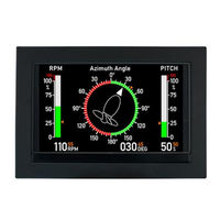
Deif XDi 96 Flexible Display Indicator Manuals
Manuals and User Guides for Deif XDi 96 Flexible Display Indicator. We have
1
Deif XDi 96 Flexible Display Indicator manual available for free PDF download: Designers Handbook
Deif XDi 96 Designers Handbook (206 pages)
FleXible Display indicator
Brand:
Deif
| Category:
Measuring Instruments
| Size: 10 MB
Table of Contents
Table of Contents
2
Useful Reference Documents
9
General Information
10
Warnings, Legal Information, and Safety
10
Warnings and Notes
10
Legal Information and Disclaimer
10
Safety Issues
10
Electrostatic Discharge Awareness
11
Factory Settings
11
About the Designer's Handbook
11
General Purpose
11
Intended Users
11
Contents and Overall Structure
11
Product Introduction
12
Virtual Indicator Library
13
Product Profile (PP)
14
Virtual Indicator (VI)
14
VI-Setup Profile (VS)
15
Library Types
15
XDI Type and Related Library Classes
15
Upload a New Library
16
Input Data for XDI
16
Object Dictionary - Object Index Table
16
Data Type Instance
16
Sourcing Data to the XDI
17
Canopen TPDO or RPDO (1)
17
XDI-Net as Data Input (2)
18
DAM-MPDO as Data Input (3)
19
SDO Data Transfer (3A)
19
Analogue Data Input (4)
19
Digital Data Input (5)
20
NMEA Serial Data Input (6)
20
NMEA Serial Data Output (7A and 7B)
21
Change Selected Input Via Menu
21
Multi Sources and Automatic Fall-Back
21
Example - Fall-Back Function Used in the Standard Heading Indicator Library
22
Menu Structure
26
Installation Wizard
27
Surveyor Info
27
General Menu Structure
28
Soft Keys Description (Left to Right)
28
Submenus
28
Installation
31
Unpacking
31
Esd
31
Box Content
31
Panel Mounting of XDI
31
Cut-Out and Mounting Depth Behind Panel
31
Waterproof Mounting
32
Mounting Instructions
32
Installing a CAN Bus System
33
XDI CAN Bus Ports
33
CAN Bus System Wiring
33
CAN Backbone and Termination
33
CAN Bus Cable Recommendation
34
Shielding and Grounding of the CAN Bus Cables
35
XDI Power Supply and CAN Connections
36
Strain Relief of Cable and Termination of Cable Shield
36
Supply Voltage Monitoring
37
Warning/Alert Output
38
First Time Setup Using the Wizard
38
Rotate the Display180
38
Manual Setup Procedure
38
Step 1 - Select CAN Node ID
38
Step 2 - Select Product Profile
39
Step 3 - Select Virtual Indicator
39
Step 4 - Select VI Setup Profile
40
Step 5 - Finish - XDI Without NX2 Module
40
Step 5 - NMEA Setup - XDI with NX2 Module
40
NMEA Auto Scan and Input Selection
41
NMEA Auto Setup Example
41
Change NMEA Setup
46
Skipping the Wizard
46
Automated XDI Setup Via CAN
47
Detailed Product Description
48
XDI CAN Bus
48
Detailed XDI-Net/Canopen Description
48
XDI-Net for Easy Integration
48
CAN Nodeid
48
Overall CAN Bus Parameter Settings
50
Important XDI-Net Restrictions
50
The CAN Bus Mode
51
CAN Bus Changes Via Menu
51
Error Indication
52
XL, BW, BRW-2 and TRI-2 with Scan
54
Extension Modules
54
AX1 Analogue Extension Module
55
Reference Voltage for Potentiometer Applications
55
Analogue Input Types
55
Analogue Scaling
56
Analogue Multi-Point Linearisation
57
AX1 Input Circuit - Principle Diagram
59
Input Protection
59
Common Mode Rejection
60
Connecting to the AX1 Module
64
Configuration of the AX1 Module
65
Share Analogue Data Via CAN
78
DX1 Digital Extension Module
79
DX1 Input Circuit - Principle Diagram
79
Connecting to the DX1 Module
79
Digital Inputs Configuration
80
Digital Dimmer Input
84
Relay Outputs
85
NX1 and NX2 NMEA Interface Module
87
Connection of the NX Modules
87
Connection and Cable for NMEA
88
NMEA Inputs
88
NMEA Outputs
88
Contact Inputs
88
XDI Menu System and Functions
90
XDI Menu Level 1 - Short Push
90
Dimmer Level Up/Down (Button 2 and 3)
90
Menu Level 1 Functions Only in XDI-N
91
Toggle between Screens (Button 1)
91
Using Screen Mode Grouping in System Integration
91
Quick Menu (Only XDI-N)
92
Change Unit Profile
92
Change Unit Profile Setup
93
Change Unit Profile in a CAN Bus System
94
Mode Group Setup
94
Date/Time Setup
100
Quick Access to the User Menu
103
Menu Level 2 - Long Double Push (Easy Access)
104
Surveyor Information (INFO)
105
Master Reset
105
User Menu
107
Dimmer
107
Normal Dimmer Function
107
Fixed Dimmer Level
108
Dimmer Groups
109
Dimmer Setup
111
Day/Night Colour Shift
118
Virtual Indicator Colour Modes
118
Auto Day/Night Shift Mode
121
Warning and Sound
123
Warning Log
123
Warning Setup
124
Warning Marks
125
Sound Setup
126
Rotate Display
126
Installation Menu
126
Accessing the Installation Menu
127
Restart Setup Wizard
127
Edit Virtual Indicator
128
Text and Units
128
Warning Marks/Restricted Band
131
Indicators
133
Adjust Input Settings
135
XDI-Net - Input Adjust and Special Use
136
XDI-Net Adjust Menu - Prop RPM% Set Point 1
136
Canopen MPDO as Data Source
137
Canopen TPDO/RPDO Input Adjust
138
PDO Converter for Azimuth/Rudder
138
Canopen Rudder Transmitter (for Example DEIF RTC 600)
140
PDO Converter for Pitch
140
PDO Converter for RPM
141
Universal PDO Converters
143
Advanced CAN Functions
143
Canopen PDO Converter Synchronisation Via XDI-Net
143
AX1 Analogue Input Adjust
144
AX1 Analogue Input - Azimuth/Rudder Set Point 1
144
AX 1 Analogue Input for RPM Set Point
147
DX1 Digital Input Adjust
149
DX1 Digital RPM from Pickup
149
External Input for Control Flags
151
AX1 - Analogue Input as "Digital" Control Input
151
DX1 - Universal Digital Input of a Control Flag
152
DX1 Relay Output Adjust
152
Product-Related Events
153
Relay Mode
153
Relay Event Mode
153
Indicator-Related Relay Setup
158
Relay Activation Indication on a VI
160
NMEA Output Using NX1 (or NX2)
160
NMEA Output in Standard Virtual Indicators
161
NX1/NX2 NMEA0183 Setup Menu
161
COM Port Setup
162
NMEA Output Setup
163
NMEA Input Setup (NX2 Only)
165
When Is Manual NMEA Input Selection Necessary
171
Manual Input Configuration
171
Adjust a Wind Sensor Misalignment from a Menu
171
Changing Filter Settings
173
The Other Input Configuration Parameters
174
CAN Bus Changes Via Menu
174
Service Menu
175
NMEA Monitor
175
Product Information Page
179
Product Configuration Page
180
Trouble Shooting Help
180
Appendix 1: Colour Calibration - Service Instruction
181
Display Colour Calibration
181
Introduction
181
Colour and Backlight Adjustment
182
Access the New Display Calibration Function
182
Display Calibration
183
Menu Functions
183
Colour Adjustment
183
Some Experience
184
Save or Undo Your Display Calibration
184
What Happens if You Install a New Library Package
185
Master Reset
185
Display Calibration Step by Step (Example)
186
Reservation
187
Appendix 2: Application Examples
189
Application 1 - XDI Azimuth System, Canopen and XDI-Net
189
Azimuth and RPM Indicator System with Set Point
189
Azimuth, Pitch and RPM System with Set Point
191
Application 2 - Azimuth Canopen and Analogue System
193
Azimuth and RPM Indicator System with Set Point
193
Azimuth, Pitch and RPM System with Set Point
194
Application 3 - Azimuth Analogue System Using XDI-Net
195
Azimuth and RPM Indicator System with Set Point
195
Azimuth, Pitch and RPM System with Set Point
196
Application 4 - Azimuth, RPM Pickup Analogue System Using XDI-Net
198
Azimuth and RPM Indicator System with Set Point
198
Azimuth, Pitch and RPM System with Set Point
199
Application 5 - XDI Rudder System Using Canopen and XDI-Net
200
System Overview
201
Setup Procedure
201
Application 6: XDI Rudder System, Analogue Angle Transmitter and XDI-Net
202
System Overview
202
Setup Procedure
203
Application 7 - Dimmer Control
203
XDI-Net, CAN TPDO or Analogue Dimmer Using AX1
204
Push-Button Dimmer Using DX1
204
Application 8 - Group Dimmer Control
205
Terminology, Terms, and Abbreviations
206
Advertisement
Advertisement
Related Products
Deif XDi Series
Deif XDi 144
Deif XDi 192
Deif XL72
Deif XL96
Deif XL144
Deif XL192
Deif XL
Deif BRW-2
Deif BW
Deif Categories
Controller
Measuring Instruments
Control Unit
Monitor
Control Systems
More Deif Manuals
Login
Sign In
OR
Sign in with Facebook
Sign in with Google
Upload manual
Upload from disk
Upload from URL