Table of Contents
Advertisement
Quick Links
Advertisement
Table of Contents

Related Manuals for Allied Telesis AT-IMC1000T/SFP


Summary of Contents for Allied Telesis AT-IMC1000T/SFP
- Page 1 AT-IMC1000T/SFP Industrial Gigabit Media Converter User Manual 613-001978 Rev A...
- Page 2 Allied Telesis, Inc. has been advised of, known, or should have known, the possibility of such damages. AT-IMC1000T/SFP Industrial Gigabit PoE+ Media Converter User Manual...
- Page 3 • II CE Mark Warning This is a Class-A product. In a domestic environment this product may cause radio interference in which case the user may be required to take adequate measures. AT-IMC1000T/SFP Industrial Gigabit PoE+ Media Converter User Manual...
-
Page 4: Table Of Contents
Installing Copper Ethernet Cable ................. 16 Installing SFP Module and Fiber Cable ............... 16 Hardware Installation ....................17 Selecting a Location ..................... 17 Installation Steps......................17 Troubleshooting .......................21 Reviewing the Safety Guidelines ...................22 AT-IMC1000T/SFP Industrial Gigabit PoE+ Media Converter User Manual... -
Page 5: Overview
“fiber to building” applications at central offices or local sites. On the copper port, it supports MDI/MDIX auto detection, so you don’t need to use crossover wires. Furthermore, the AT-IMC1000T/SFP can work normally in an extended temperature range from -40°C to 75°C and accepts a wide voltage range from +12 ~ 48 VDC. -
Page 6: Features
Wide Operating Temperature: -40°C to 75°C ture Operating Humidity 5% to 95% Storage Environment -40°C to 85°C Dimensions Metal case. IP-30, 30mm (W) x 140mm (H) x 95mm (D) Installation DIN-Rail and Wall-mount design AT-IMC1000T/SFP Gigabit Ethernet Industrial Media Converter... -
Page 7: Packing List
IEC60068-2-32 (Free fall), IEC60068-2-27 (Shock), IEC60068-2-6 (Vibration) 1.3 Packing List • 1 x AT-IMC1000T/SFP Industrial Gigabit Media Converter 1 set of Wall Mount kit (2 brackets and 4 screws) • 1 x ATI Product Insert and China-RoHS HS/TS Substances Concentration Chart •... -
Page 8: Hardware Description
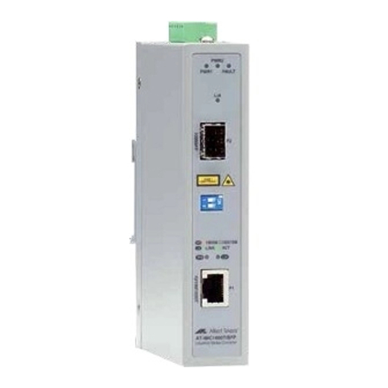
In this paragraph, we will introduce the Industrial Media Converter’s hardware spec, port, cabling information, and wiring installation. 2.1 Front Panel The Front Panel of the AT-IMC1000T/SFP Industrial Media Converter is shown as below. FIGURE 2-1 Front Panel of the Industrial Media Converter 2.2 Top View The top panel of the Industrial Media Converter is equipped one terminal block connector of two DC power inputs. -
Page 9: Wiring The Power Inputs
1. Insert the positive and negative wires into the V+ and V- contacts on the terminal block connector. FIGURE 2-4 Wire-clamp Screws 2. Tighten the wire-clamp screws to prevent the wires from loosing. AT-IMC1000T/SFP Industrial Gigabit PoE+ Media Converter User Manual... -
Page 10: Wiring The Fault Alarm Contact
Green Fiber connected to network Blink Networking is active Fiber not connected to network Amber Link to 1000 Mbps network Not connected to network or not working at speed of 1000M AT-IMC1000T/SFP Industrial Gigabit PoE+ Media Converter User Manual... -
Page 11: Dip-Switch
Auto MDI/MDIX means that you can connect to another switch or workstation without chang- ing straight through or crossover cabling. See figures as below for straight through and crossover cable schematic. AT-IMC1000T/SFP Industrial Gigabit PoE+ Media Converter User Manual... - Page 12 6 TD- 6 TD- 1 RD+ 1 RD+ 2 RD- 2 RD- Media Converter Router or PC 3 TD+ 3 TD+ 6 TD- 6 TD- 1 RD+ 1 RD+ 2 RD- 2 RD- AT-IMC1000T/SFP Industrial Gigabit PoE+ Media Converter User Manual...
-
Page 13: Mounting Installation
3.1 DIN-Rail Mounting The DIN-Rail clip is screwed on the AT-IMC1000T/SFP Industrial Media Converter when out of factory. If the DIN- Rail clip is not installed on the back of the media converter, please see the following figure to screw the DIN-Rail on the switch. - Page 14 4. Lightly push the chassis down onto the upper DIN-Rail track until the bottom of the chassis can swing back toward the wall and under the bottom DIN-Rail track. See Figure 3-2. FIGURE 3-3 Push the chassis down AT-IMC1000T/SFP Industrial Gigabit PoE+ Media Converter User Manual...
-
Page 15: Wall-Mount Plate Fixing
DIN-Rail. 6. To remove the AT-IMC1000T/SFP Industrial Media Converter, lightly press down on the chassis and pull the bottom of the chassis away from the bottom DIN-Rail track. Then lift the chassis up off the upper DIN-Rail track. -
Page 16: Cabling Installation
Insert the proper SFP module and connect fiber cabling as explained in steps 7 and 8 of paragraph 5.2. The SFP port (P2) LED on the unit will light up when the AT-IMC1000T/SFP is powered on and the link partner net- work device is active,. -
Page 17: Hardware Installation
Here are the guidelines for choosing a location for the media converter: • The AT-IMC1000T/SFP Industrial Media Converter may be installed on a desktop, on a wall or on DINRAIL. Note: The DINRAIL bracket must be ordered separately from the AT-PC2002/POE+ media converter The power outlet should be located near the unit and be easily accessible. - Page 18 7. Insert the transceiver into the SFP module. Notice that the triangle mark is the bottom of the module. FIGURE 5-1 SFP module to bay FIGURE 5-2 SFP module inserted into its bay AT-IMC1000T/SFP Industrial Gigabit PoE+ Media Converter User Manual...
- Page 19 See Figure 2-6 for the location of the fiber cable release tabs. FIGURE 5-4 Remove LC connector 2. Second, push down the metal loop and pull the SFP module out by the plastic part. AT-IMC1000T/SFP Industrial Gigabit PoE+ Media Converter User Manual...
- Page 20 Hardware Installation Installation Steps FIGURE 5-5 Pull out the SFP module AT-IMC1000T/SFP Industrial Gigabit PoE+ Media Converter User Manual...
-
Page 21: Troubleshooting
• If the LED indicators are normal and the connected cables are correct and the packets still cannot transmit. Please check your system's Ethernet devices' configuration or status. AT-IMC1000T/SFP Industrial Gigabit PoE+ Media Converter User Manual... -
Page 22: Reviewing The Safety Guidelines
The protection provided by the equipment may be impaired if the equipment is used in a manner not specified by Allied Telesis, Inc. Do not remove the cover from the unit or change any of the internal cables or wiring. Only an authorized Allied Telesis service technician should make repairs to this device. - Page 23 Caution: The unit does not contain serviceable components. Please return damaged units for servicing. E42 Caution: During normal operations, the SFP module may have a case temperature that exceeds 70° C (158° F). If you remove the module, exercise caution when handling with unprotected hands. E43 AT-IMC1000T/SFP Industrial Gigabit PoE+ Media Converter User Manual...
Need help?
Do you have a question about the AT-IMC1000T/SFP and is the answer not in the manual?
Questions and answers