
Related Manuals for Allied Telesis AT-IMC1000TP/SFP


Summary of Contents for Allied Telesis AT-IMC1000TP/SFP
- Page 1 AT-IMC1000TP/SFP Industrial Gigabit PoE+ Media Converter User Manual 613-001966 Rev A...
- Page 2 Allied Telesis, Inc. has been advised of, known, or should have known, the possibility of such damages. AT-IMC1000TP/SFP Industrial Gigabit PoE+ Media Converter...
- Page 3 Consult the dealer or an experienced radio/TV technician for help. • II CE Mark Warning This is a Class-A product. In a domestic environment this product may cause radio interference in which case the user may be required to take adequate measures. AT-IMC1000TP/SFP Industrial Gigabit PoE+ Media Converter...
-
Page 4: Table Of Contents
Table of Contents Overview ..........................5 Introduction ........................5 Features........................... 6 Packing List ........................7 Supported SFP ........................ 7 Safety Precaution......................7 Hardware Description ......................8 Front Panel........................8 Top View ........................8 Wiring the Power Inputs....................9 LED Indicators ......................10 SFP Speed DIP-Switch.................... -
Page 5: Overview
EMI immunity and long-distance transmission capability. Therefore, the AT-IMC1000TP/SFP is an ideal solution for “fiber to building” applications at central offices or local sites.The SFP slot accepts one of a range of SFP fiber modules which allows you to customize the speed (100M/1000M) and dis- tance capability of the fiber optic port for your installation. -
Page 6: Features
32.725W Operating Tempera- -40°C to 75°C ture Operating Humidity 5% to 95% (non-condensing) Storage Environment -40°C to 85°C Dimensions Metal case, IP-31 36.7mm (W) x 108.4mm (H) x 94.5mm (D) Installation DIN-Rail, Wall-mount (optional) AT-IMC1000TP/SFP Gigabit PoE+ Industrial Media Converter... -
Page 7: Packing List
1 x ATI Product Insert and China-RoHS HS/TS Substances Concentration Chart • 1.4 Supported SFP For a list of supported transceivers, refer to the AT-IMC1000TP/SFP Data Sheet which can be found on the AT- IMC1000TP/SFP 2-Port Gigabit Ethernet PoE+ Industrial Media Converter product page at alliedtelesis.com. 1.5 Safety Precaution Warning: Please use a protection devices on the inputs of the power supplies that supply DC voltage to the AT- IMC1000TP/SFP Gigabit PoE+ Industrial Media Converter. -
Page 8: Hardware Description
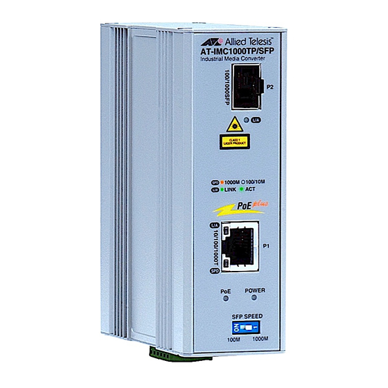
In this section, we will introduce the Industrial Gigabit Media Converter’s hardware spec, port, cabling information, and wiring installation. 2.1 Front Panel The Front Panel of the AT-IMC1000TP/SFP Industrial Gigabit Media Converter is shown as below. FIGURE 2-1 Front Panel of the Industrial Gigabit Media Converter 2.2 Top View For IP31 rating, the top panel of the device is without terminal block. -
Page 9: Wiring The Power Inputs
The wire gauge for the terminal block should be in the range between 12~ 24 AWG 3. To tighten the wire-clamp screws located at the bottom of the unit (see above picture) highlighted in red for pre- venting DC wires loosing AT-IMC1000TP/SFP Industrial Gigabit PoE+ Media Converter... -
Page 10: Led Indicators
4. Tighten the two screws on each end of the connector to secure it to the chassis. 2.4 LED Indicators The LEDs located on the front panel of the AT-IMC1000TP/SFP display power status and network status. Each of them has its own specific meaning as below table. -
Page 11: Sfp Speed Dip-Switch
The table below shows the 10BASE-T/ 100BASE-TX /1000Base-T MDI and MDI-X port pin outs. Table 2-4: MDI/MDI-X Pin Assignments Pin MDI-X Signal Name MDI Signal Name Receive Data plus Transmit Data plus (RD+) (TD+) Receive Data minus Transmit Data minus (RD-) (TD-) AT-IMC1000TP/SFP Industrial Gigabit PoE+ Media Converter... - Page 12 Transmit and receive data 2 (positive lead) TRD-(2) Transmit and receive data 2 (negative lead) TRD-(1) Transmit and receive data 1 (negative lead) TRD+(3) Transmit and receive data 3 (positive lead) TRD-(3) Transmit and receive data 3 (negative lead) AT-IMC1000TP/SFP Industrial Gigabit PoE+ Media Converter...
- Page 13 Fiber segment using single-mode connector type must use 9/125μm single-mode fiber cable. You can connect two devices in the distance supported by SFP modules. Fiber segment using multi-mode connector type must use 50/ 125 or 62.5/125μm multi-mode fiber cable. You can connect two devices up to 550m distances. AT-IMC1000TP/SFP Industrial Gigabit PoE+ Media Converter...
-
Page 14: Mounting Installation
1. Use the screws to screw on the DIN-Rail clip on the industrial switch. 2. To remove the DIN-Rail clip, reverse step 1. FIGURE 3-1 DIN-Rail Bracket Mounting Screw Location 3. First, insert the top of DIN-Rail bracket onto the top of the DIN-Rail track. AT-IMC1000TP/SFP Industrial Gigabit PoE+ Media Converter... - Page 15 FIGURE 3-3 Bottom of DIN-Rail Bracket Attached to Bottom of DIN-Rail 5. Check the DIN-Rail clip is tightly fixed on the track. 6. To remove the industrial switch from the track, reverse the steps above. AT-IMC1000TP/SFP Industrial Gigabit PoE+ Media Converter...
-
Page 16: Wall-Mount Plate Fixing
5. Use the hook holes at the corners of the wall-mount plates to hang the industrial switch on the wall. 6. To remove the wall-mount plates, reverse the steps above. FIGURE 3-4 Attaching Wall Mount Plates AT-IMC1000TP/SFP Industrial Gigabit PoE+ Media Converter... -
Page 17: Cabling Installation
Insert the proper SFP module and connect fiber cabling as explained in steps 7 and 8 of paragraph 5.2.1. The SFP port (P2) LED on the unit will light up when the AT-IMC1000TP/SFP is powered on and the link partner net- work device is active,. -
Page 18: Hardware Installation
4. To hang the unit on the DIN-Rail track or wall, please refer to the Mounting Installation section. 5. Power on the AT-IMC1000TP/SFP and the power LED indicator on the unit will light up. Please refer to the Wir- ing the Power Inputs section on how to wire the power. - Page 19 Installation Steps 7. Insert the transceiver into the SFP module. Notice that the triangle mark is the bottom of the module. FIGURE 5-1 Insertion of a transceiver into the SFP module FIGURE 5-2 Transceiver inserted AT-IMC1000TP/SFP Industrial Gigabit PoE+ Media Converter...
- Page 20 FIGURE 5-3 LC connector to the transceiver 5.2.2 Removing the LC connector from the transceiver 1. Press the upper side of the LC connector from the transceiver and pull it out to release FIGURE 5-4 Remove the LC connector AT-IMC1000TP/SFP Industrial Gigabit PoE+ Media Converter...
- Page 21 Hardware Installation Installation Steps 2. Push down the metal loop and pull the transceiver out by the plastic part. FIGURE 5-5 Pull out from the SFP module AT-IMC1000TP/SFP Industrial Gigabit PoE+ Media Converter...
-
Page 22: Troubleshooting
• If the LED indicators are normal and the connected cables are correct and the packets still cannot transmit, please check your system's Ethernet devices' configuration or status. AT-IMC1000TP/SFP Industrial Gigabit PoE+ Media Converter... -
Page 23: Reviewing The Safety Guidelines
The protection provided by the equipment may be impaired if the equipment is used in a manner not specified by Allied Telesis, Inc. Do not remove the cover from the unit or change any of the internal cables or wiring. Only an authorized Allied Telesis service technician should make repairs to this device. - Page 24 Caution: The unit does not contain serviceable components. Please return damaged units for servicing. E42 Caution: During normal operations, the SFP module may have a case temperature that exceeds 70° C (158° F). If you remove the module, exercise caution when handling with unprotected hands. E43 AT-IMC1000TP/SFP Industrial Gigabit PoE+ Media Converter...
Need help?
Do you have a question about the AT-IMC1000TP/SFP and is the answer not in the manual?
Questions and answers