
Related Manuals for Allied Telesis AT-MCF2000 Series


Summary of Contents for Allied Telesis AT-MCF2000 Series
- Page 1 AT-MCF2000 Multi-channel Media Converter Series Fast and Gigabit Ethernet Media Converter Modules: AT-MCF2012LC AT-MCF2012LC/1 AT-MCF2032SP Enclosures: AT-MCF2000 AT-MCF2300 ◆ Installation Guide 613-001052 Rev. A...
- Page 2 Allied Telesis, Inc. reserves the right to make changes in specifications and other information contained in this document without prior written notice. The information provided herein is subject to change without notice. In no event shall Allied Telesis, Inc. be liable for any incidental, special, indirect, or consequential damages whatsoever, including but not limited to lost profits, arising out of or related to this manual or the information contained herein, even if Allied Telesis, Inc.
- Page 3 Electrical Safety and Emissions Standards This product meets the following standards. U.S. Federal Communications Commission Radiated Energy Note: This equipment has been tested and found to comply with the limits for a Class A digital device pursuant to Part 15 of FCC Rules.
- Page 4 PDF document titled “Translated Safety Statements” (613-000990) posted on the Allied Telesis website at www.alliedtelesis.com. This document is also included on the documentation CD that is shipped with the product.
-
Page 5: Table Of Contents
Contents Preface ................................13 How this Guide is Organized ..........................14 Where to Find Web-based Guides ........................16 Contacting Allied Telesis ..........................17 Online Support ............................17 Email and Telephone Support........................17 Returning Products ............................ 17 Sales and Corporate Information ....................... 17 Warranty.............................. - Page 6 Contents Stack Port ................................. 62 Reset Button ..............................63 SD Slot ................................65 Chassis ID Jumper............................66 LEDs ................................. 67 General Status LEDs..........................67 RS-232 Terminal Port LED......................... 68 10/100/1000Base-T Management Port LEDs..................... 69 ID LEDs ..............................70 Stack Port LED ............................70 Secure Digital Memory Card Slot LED .......................
- Page 7 AT-MCF2000 Media Converter Series Installation Guide Chapter 22: Starting a Local Management Session ................. 143 Chapter 23: Troubleshooting the Modules ....................145 AT-MCF2012LC, AT-MCF2012LC/1 and AT-MCF2032SP Media Converter Modules........146 AT-MCF2000AC and AT-MCF2300AC Power Supply Modules..............150 AT-MCF2KFAN and AT-MCF2300FAN Modules ................... 151 AT-MCF2000M Management Module ......................
- Page 8 Contents...
- Page 9 Figure 1: AT-MCF2000 and AT-MCF2300 Chassis......................27 Figure 2: AT-MCF2000 Chassis Slots ..........................28 Figure 3: AT-MCF2300 Chassis Sots ...........................29 Figure 4: AT-MCF2000 Series Media Converter Module .....................32 Figure 5: Front Panel of the AT-MCF2012LC Module ......................33 Figure 6: Front Panel of the AT-MCF2012LC/1 Module .......................33 Figure 7: Front Panel of the AT-MCF2032SP Module......................33...
- Page 10 Figures Figure 50: Removing a Blank Cover from a Media Converter Slot ..................107 Figure 51: Removing the Battery Insulator .........................108 Figure 52: Installing a Media Converter Module .........................109 Figure 53: Securing a Media Converter Module .........................109 Figure 54: Removing the Blank Panel from the Management Slot ..................111 Figure 55: Setting the Chassis ID Jumper on the AT-MCF2000M Management Module...........113 Figure 56: Removing the Battery Insulator .........................113 Figure 57: Installing the Management Module........................114...
- Page 11 Tables Table 1: Hardware Components ............................22 Table 2: Management Software ............................25 Table 3: AT-MCF2000 Chassis Slots ..........................28 Table 4: AT-MCF2300 Chassis Slots ..........................29 Table 5: Twisted Pair Cabling and Distances ........................35 Table 6: Fiber Optic Ports ..............................36 Table 7: “A” Activity LED ..............................42 Table 8: Link LEDs in the Link Test Mode ...........................44 Table 9: “L”...
- Page 12 Tables...
-
Page 13: Preface
Preface This is the installation guide for the AT-MCF2000 Series of multi-channel, Fast and Gigabit Ethernet media converter products. In this guide you’ll learn about the features of the product and how to install the components. This preface contains the following sections: “How this Guide is Organized”... -
Page 14: How This Guide Is Organized
The chapters in the second section contain the installation instructions. If you are installing a new system, Allied Telesis recommends that you perform the chapters as they are presented in the section, skipping any chapters that are not relevant to your installation. To upgrade or expand an existing system, go straight to the appropriate chapters. - Page 15 AT-MCF2000 Media Converter Series Installation Guide Chapter 14, “Installing the AT-MCF2000S Stacking Module” on page Chapter 15, “Installing the Chassis in an Equipment Rack” on page Chapter 16, “Grounding the AT-MCF2300 Chassis” on page 123 Chapter 17, “Installing the SFP Modules in the AT-MCF2032SP Module”...
-
Page 16: Where To Find Web-Based Guides
Preface Where to Find Web-based Guides The installation and user guides for all of the Allied Telesis products are available for viewing in portable document format (PDF) from our web site at www.alliedtelesis.com. -
Page 17: Contacting Allied Telesis
All the products in the AT-MCF2000 Media Converter Series have a 2 Year Warranty. All Allied Telesis warranties are subject to the terms and conditions set out in the Allied Telesis Limited Warranties on our web site at www.alliedtelesis.com/warranty. Management... - Page 18 Preface...
-
Page 19: Section I: Features
Section I Features The chapters in this section are listed here: Chapter 1, “AT-MCF2000 Multi-channel Media Converter Series” on page 21 Chapter 2, “AT-MCF2000 and AT-MCF2300 Chassis” on page 27 Chapter 3, “AT-MCF2012LC, AT-MCF2012LC/1 and AT-MCF2032SP Modules” on page 31 Chapter 4, “AT-MCF2000M Management Module”... - Page 20 Section I: Features...
-
Page 21: Chapter 1: At-Mcf2000 Multi-Channel Media Converter Series
Chapter 1 AT-MCF2000 Multi-channel Media Converter Series The multi-channel media converters in the AT-MCF2000 Series are a simple and reliable method for consolidating large numbers of geographically separated Fast Ethernet or Gigabit Ethernet networks into a central location over fiber optic cable. -
Page 22: Hardware Components
SFP module. The SFP slots let you customize the channels for different operating distances. For the list of supported SFP modules, contact your Allied Telesis sales representative. 1389 AT-MCF2000 This 1U chassis has slots for two 12-channel media... - Page 23 AT-MCF2000 Media Converter Series Installation Guide Table 1. Hardware Components Component Description AT-MCF2300 This 3U chassis can accommodate up to four 12- channel media converter modules, primary and redundant power supplies, and the optional management or stacking module. AT -M CF 2K PN L1 AT -M...
- Page 24 Chapter 1: AT-MCF2000 Multi-channel Media Converter Series Table 1. Hardware Components Component Description AT-MCF2300AC This is the power supply module for the AT-MCF2300 Chassis. The chassis can accommodate two power modules for redundancy. AT -M C F2 30 0A 1392 AT-MCF2KFAN This is the cooling module for the AT-MCF2000 Chassis.
-
Page 25: Management Software Components
AT-MCF2000 Media Converter Series Installation Guide Management Software Components Table 2 lists the management software programs of the AT-MCF2000 Media Converter Series. Table 2. Management Software Management Software Description AT-S85 This is the management software for the AT-MCF2012LC, AT-MCF2012LC/1 and AT-MCF2032SP Media Converter Modules. - Page 26 Chapter 1: AT-MCF2000 Multi-channel Media Converter Series Section I: Features...
-
Page 27: Chapter 2: At-Mcf2000 And At-Mcf2300 Chassis
Chapter 2 AT-MCF2000 and AT-MCF2300 Chassis The AT-MCF2000 Chassis and the AT-MCF2300 Chassis are illustrated in Figure 1. AT-MCF2000 AT -M C F2 K P N L1 AT -M C F2 K P N L1 1415 AT-MCF2300 A T- M C F 2K P N L A T- M... -
Page 28: Figure 2: At-Mcf2000 Chassis Slots
Chapter 2: AT-MCF2000 and AT-MCF2300 Chassis Figure 2 shows the front and back panels of the AT-MCF2000 Chassis. AT-MCF2KPNL1 AT-MCF2KPNL1 1107-a Slots 1 and 2 MANAGEMENT AT-MCF2KPNL2 AT-MCF2KPNL2 AT-MCF2KPNL3 1108-a Slot B Slot A Management Slot Figure 2. AT-MCF2000 Chassis Slots Table 3 lists the slots in the unit. -
Page 29: Figure 3: At-Mcf2300 Chassis Sots
AT-MCF2000 Media Converter Series Installation Guide Figure 3 illustrates the front and back panels of the AT-MCF2300 Chassis. Slots 1 to 4 AT-MCF2KPNL1 AT-MCF2KPNL1 AT-MCF2KPNL1 AT-MCF2KPNL1 MANAGEMENT AT-MCF2KPNL2 AT-MCF2KPNL2 AT-MCF2KPNL3 Slot A Management Slot B Slot AT-MCF2300FAN Module Fan Cover AT-MCF2300FAN STATUS NORMAL... - Page 30 Chapter 2: AT-MCF2000 and AT-MCF2300 Chassis Table 4. AT-MCF2300 Chassis Slots Slot/Module Module A and B These slots are for the AT-MCF2300AC Power Supply Module. The chassis requires only one power supply module, but a second module can be installed for power redundancy. If there are two power supply modules in the unit, they load- share the power requirements of the chassis.
- Page 31 Chapter 3 AT-MCF2012LC, AT-MCF2012LC/1 and AT-MCF2032SP Modules This chapter contains the following sections: “Overview” on page 32 ❒ “Front Panels” on page 33 ❒ “Media Converter Channels” on page 34 ❒ “Twisted Pair Ports” on page 35 ❒ “Fiber Optic Ports” on page 36 ❒...
-
Page 32: Chapter 3: At-Mcf2012Lc, At-Mcf2012Lc/1 And At-Mcf2032Sp Modules
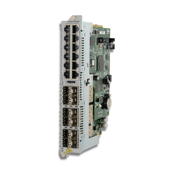
(CRC) detection to prevent the propagation of incomplete or fragmented packets on your network. 1390 Figure 4. AT-MCF2000 Series Media Converter Module The standards and features of the modules are listed here: IEEE 802.3 10Base-T ❒... -
Page 33: Front Panels
AT-MCF2000 Media Converter Series Installation Guide Front Panels The model names can be found on the left side of the faceplates. Figure 5 shows the front panel of the AT-MCF2012LC Media Converter Module. CH11 CLASS 1 LED PRODUCT CH10 CH12 1119 Figure 5. -
Page 34: Media Converter Channels
Chapter 3: AT-MCF2012LC, AT-MCF2012LC/1 and AT-MCF2032SP Modules Media Converter Channels The media converter modules have twelve independent media converter channels that forward Fast or Gigabit Ethernet network traffic. Each channel has one twisted pair port and one fiber optic port. The channels on the AT-MCF2012LC and AT-MCF2012LC/1 Media Converter Modules have 10/100Base-TX twisted pair ports and 100Base-FX fiber optic ports. -
Page 35: Twisted Pair Ports
AT-MCF2000 Media Converter Series Installation Guide Twisted Pair Ports Table 5 lists the cable specifications for the twisted pair ports. Table 5. Twisted Pair Cabling and Distances Maximum Speed Cable Type Operating Distance 10 Mbps Standard TIA/EIA 568-B-compliant 100 m (328 ft) Category 3 or better shielded or unshielded cabling with 100 ohm impedance and a frequency of 16... -
Page 36: Fiber Optic Ports
Chapter 3: AT-MCF2012LC, AT-MCF2012LC/1 and AT-MCF2032SP Modules Fiber Optic Ports Table 6 lists the specifications for the fiber optic cabling for the AT-MCF2012LC and AT-MCF2012LC/1 Media Converter Modules. Table 6. Fiber Optic Ports Maximum Media Converter Connector Operating Fiber Optic Cable Module Distance AT-MCF2012LC... -
Page 37: Channel Operating Modes
AT-MCF2000 Media Converter Series Installation Guide Channel Operating Modes The media converter channels support these operating modes: Link Test mode ❒ MissingLink mode ❒ Smart MissingLink mode ❒ The operating modes of the channels are set with the Mode button on the front panel of the module explained in “Mode Button”... - Page 38 Instead, you might set the channel to the Link Test mode. Furthermore, Allied Telesis does not recommend using the MissingLink mode when you’re trying to troubleshoot a network problem that might have its roots with a link problem.
-
Page 39: Smart Missinglink Mode
AT-MCF2000 Media Converter Series Installation Guide diagnose the problem. Rather, you should use the Link Test or the Smart MissingLink modes to troubleshoot a link problem. Smart The Smart MissingLink mode, the third operating mode of the media converter channels, is nearly identical to the MissingLink mode. It, too, MissingLink enables the ports of a channel to pass the “Link”... -
Page 40: Guidelines To Using The Channel Operating Modes
SNMP traps. Allied Telesis does not recommend using the Smart MissingLink mode ❒ on a channel that is connected to managed devices. As explained in “Smart MissingLink Mode”... -
Page 41: Port And Channel Leds
AT-MCF2000 Media Converter Series Installation Guide Port and Channel LEDs The LEDs on a media converter module reflect packet activity, link status, duplex mode and collisions of the ports, as well as the operating modes of the channels. “A” Activity LED The Activity (A) LEDs blink whenever the ports are transmitting or receiving network packets. -
Page 42: L" Link Leds
Chapter 3: AT-MCF2012LC, AT-MCF2012LC/1 and AT-MCF2032SP Modules Activity LEDs Figure 11. Activity LEDs for the Fiber Optic Ports on the AT-MCF2032SP Module The Activity LED is defined in Table 7. Table 7. “A” Activity LED Link LED State Description A port is not receiving or transmitting network packets. -
Page 43: Figure 13: Link Led For A Fiber Optic Port On The At-Mcf2012Lc And At-Mcf2012Lc/1 Modules
AT-MCF2000 Media Converter Series Installation Guide The Link LEDs for the fiber optic ports on the AT-MCF2012LC and the AT-MCF2012LC/1 Modules are located just to the right of the ports, as shown in Figure 10. Link LED Figure 13. Link LED for a Fiber Optic Port on the AT-MCF2012LC and AT-MCF2012LC/1 Modules The Link LEDs for the fiber optic ports on the AT-MCF2032SP Module are the first pair of LEDs between the SFP slots, shown in Figure 14. -
Page 44: Table 8: Link Leds In The Link Test Mode
Chapter 3: AT-MCF2012LC, AT-MCF2012LC/1 and AT-MCF2032SP Modules Link Test Mode When a channel is set to the Link Test mode, the Link LEDs report the current states of the connections between the ports and the local and remote network devices. The Link LED of a port will be on when a port has a link to its network device and it will be off when a port does not have a link. -
Page 45: Table 9: "L" Link Leds In The Missinglink Mode
AT-MCF2000 Media Converter Series Installation Guide Table 9. “L” Link LEDs in the MissingLink Mode Link LED Channel Ports Description States Twisted Pair One or both ports in the channel Port can not establish links with their network devices. Fiber Optic Port Twisted Pair Steady Green or Both ports in the channel have... -
Page 46: Cdc And Fdc Duplex Mode And Collision Leds
Chapter 3: AT-MCF2012LC, AT-MCF2012LC/1 and AT-MCF2032SP Modules Table 10. “L” Link LEDs in the Smart MissingLink Mode (Continued) Link LED Channel Ports Description States Twisted Pair The fiber optic port in the channel Port can establish a link with its network device, but the twisted pair port is Fiber Optic Port Flashing Green... -
Page 47: Figure 15: Duplex Mode And Collision Leds On The At-Mcf2012Lc And At-Mcf2012Lc/1 Modules
AT-MCF2000 Media Converter Series Installation Guide CH11 CLASS 1 LED PRODUCT CH10 CH12 Figure 15. Duplex Mode and Collision LEDs on the AT-MCF2012LC and AT-MCF2012LC/1 Modules CLASS 1 LASER PRODUCT RDY/FLT Figure 16. Duplex Mode and Collision LEDs on the AT-MCF2032SP Module Section I: Features... -
Page 48: Ml, And Sml Channel Operating Mode Leds
Chapter 3: AT-MCF2012LC, AT-MCF2012LC/1 and AT-MCF2032SP Modules The CDC and FDC LEDs are described in Table 11. Table 11. CDC and FDC Duplex Mode and Collisions LEDs State Description The twisted pair port in the channel has not established a link with its network device. -
Page 49: Rdy/Flt Led
AT-MCF2000 Media Converter Series Installation Guide CLASS 1 LASER PRODUCT RDY/FLT Figure 18. Channel Operating Mode LEDs on the AT-MCF2032SP Module RDY/FLT LED The AT-MCF2032SP Module has a RDY/RDY LED that displays general status information about the unit. RDY/FLT CLASS 1 LASER PRODUCT RDY/FLT 1418... -
Page 50: Hbi And Hbo Heartbeat Leds
Chapter 3: AT-MCF2012LC, AT-MCF2012LC/1 and AT-MCF2032SP Modules Table 12. RDY/FLT LED State Description Steady Amber The module is storing a new version of its management software in flash memory. Caution Do not power off the chassis or remove the module when the LED is amber. Doing so may damage the module. -
Page 51: Mode Button
AT-MCF2000 Media Converter Series Installation Guide Mode Button You use the Mode button shown in Figure 21 to set the operating modes of the channels. You also use it to view the duplex mode and collisions on the ports of a channel with the CDC and FDC LEDs, explained in “CDC and FDC Duplex Mode and Collision LEDs”... -
Page 52: Figure 23: Channel Leds On The At-Mcf2032Sp Module
Chapter 3: AT-MCF2012LC, AT-MCF2012LC/1 and AT-MCF2032SP Modules Channel selection on the AT-MCF2032SP Module is indicated with the row of numbered LEDs beneath the SFP slots. CLASS 1 LASER PRODUCT RDY/FLT Figure 23. Channel LEDs on the AT-MCF2032SP Module You can select only one channel at a time. After you’ve selected a channel, the CDC and FDC LEDs reflect the duplex mode settings and the collisions of the channel’s two ports. -
Page 53: Guidelines To Using The Media Converter Modules
AT-MCF2000 Media Converter Series Installation Guide Guidelines to Using the Media Converter Modules Here are the guidelines to using the AT-MCF2012LC, AT-MCF2012LC/1, and AT-MCF2032SP Media Converter Modules. In order for two network devices to forward traffic to each other through ❒... - Page 54 Chapter 3: AT-MCF2012LC, AT-MCF2012LC/1 and AT-MCF2032SP Modules Section I: Features...
-
Page 55: Chapter 4: At-Mcf2000M Management Module
Chapter 4 AT-MCF2000M Management Module This chapter describes the optional AT-MCF2000M Management Module: “Overview” on page 56 ❒ “Front Panel” on page 58 ❒ “10/100/1000Base-T Management Port” on page 59 ❒ “RS-232 Terminal Port” on page 61 ❒ “Stack Port” on page 62 ❒... -
Page 56: Overview
Chapter 4: AT-MCF2000M Management Module Overview The AT-MCF2000M Management Module, together with its AT-S97 Management Software, lets you monitor the operations of the media converter modules and configure the parameter settings of the ports. Management is supported both locally (out-of band) through the RS-232 Terminal port on the module and remotely over a network (in-band) through the 10/100/1000Base-T Ethernet port from Telnet and SSH clients. - Page 57 Download new versions of the management software to the ❒ management module and the media converter modules. Note For the complete list of the management features, refer to the AT-S85 and AT-S97 Management Software Command Line User’s Guide, available from the Allied Telesis web site. Section I: Features...
-
Page 58: Front Panel
Chapter 4: AT-MCF2000M Management Module Front Panel Figure 25 illustrates the front panel of the AT-MCF2000M Management Module. AT-MCF2000M LINK 1000 LINK 10/100 LINK PORT ACTIVITY STACK MANAGEMENT TERMINAL BOOT FAULT RESET SYSTEM MASTER POWER 10/100/1000BASE-T RS-232 BUSY 1421 Figure 25. Front Panel of the AT-MCF2000M Management Module The components on the front panel are described here: Stack port -This port is used to connect multiple chassis together so ❒... -
Page 59: 10/100/1000Base-T Management Port
AT-MCF2000 Media Converter Series Installation Guide 10/100/1000Base-T Management Port The 10/100/1000Base-T Management port is a standard Ethernet, Fast Ethernet, and Gigabit Ethernet port that is used by the module to communicate with your network. You have to connect this port to a device on your network, such as a Fast Ethernet or Gigabit Ethernet switch, if the module will be performing any of these management functions: Remote management using the Telnet or Secure Shell (SSH) - Page 60 Chapter 4: AT-MCF2000M Management Module The wiring configuration of the port is set automatically with auto-MDI/ MDI-X to either MDI or MDI-X, depending on the wiring configuration of the end node. This allows you to use a straight-through twisted pair cable regardless of the wiring configuration of the port on the network device.
-
Page 61: Terminal Port
AT-MCF2000 Media Converter Series Installation Guide RS-232 Terminal Port You use this port for local management of the module with a console or a PC with a terminal emulation program. This management method, which does not require the module to have an Internet Protocol (IP) address, is referred to as local or out-of-band management because it is not conducted over a network. -
Page 62: Stack Port
Chapter 4: AT-MCF2000M Management Module Stack Port You use the Stack port to connect the chassis to another chassis that has the AT-MCF2000S Stacking Module so that you can manage the units simultaneously. For background information, refer to Chapter 5, “AT-MCF2000S Stacking Module”... -
Page 63: Reset Button
AT-MCF2000 Media Converter Series Installation Guide Reset Button The Reset button on the front panel of the management module is used to initialize the AT-S97 Management Software and the active master configuration file. Here are situations where you might want to reset the module: If you select a new active master configuration file and want to ❒... -
Page 64: Figure 26: Pressing The Reset Button
Chapter 4: AT-MCF2000M Management Module A T -M C F 2 0 0 0 M ST A C LI N K AC T M A N A G EM EN T 10 00 LI N K AC T 10 /1 00 TE R M LI N K IN A L... -
Page 65: Sd Slot
Software Command Line Interface User’s Guide. Note The management module supports 128 MB, 256 MB, and 512 MB secure digital memory cards from Allied Telesis. For ordering information, contact your Allied Telesis sales representative or visit our web site. Note Do not remove a secure digital memory card from the management module when the slot’s L/A LED is amber. -
Page 66: Chassis Id Jumper
Chapter 4: AT-MCF2000M Management Module Chassis ID Jumper The circuit board of the module has a jumper for setting the chassis ID number for the stacking feature. The jumper has two settings, 0 and 31. The default setting is 0. For more information, refer to “Chassis ID Numbers”... -
Page 67: Leds
AT-MCF2000 Media Converter Series Installation Guide LEDs The section describes the LEDs on the management module. General Status The System, Master and Power LEDs on the left side of the panel display general status information. LEDs AT-MCF2000M LINK 1000 LINK 10/100 LINK PORT ACTIVITY STACK... -
Page 68: Terminal Port Led
Chapter 4: AT-MCF2000M Management Module Table 14. General Status LEDs (Continued) State Description Power The management module is not receiving power or the power is not within the permitted operating range. Green The management module is receiving power. RS-232 Terminal The RS-232 Terminal port, used for local management of the chassis or stack, has a L/A (Link/Activity) LED. -
Page 69: 10/100/1000Base-T Management Port Leds
AT-MCF2000 Media Converter Series Installation Guide 10/100/1000Base- The 10/100/1000Base-T Management port has a L/A (Link/Activity) LED and a D/C (Duplex-mode/Collisions) LED. T Management Port LEDs AT-MCF2000M LINK 1000 LINK 10/100 LINK PORT ACTIVITY STACK MANAGEMENT TERMINAL BOOT FAULT RESET SYSTEM MASTER POWER 10/100/1000BASE-T... -
Page 70: Id Leds
Chapter 4: AT-MCF2000M Management Module Table 17. Duplex-mode/Collisions LED on the Management Port State Description Flashing Amber The port is operating in half-duplex mode with collisions. ID LEDs The two ID LEDs are used to identify the module’s chassis ID number. This number, which, as explained in “Chassis ID Jumper”... -
Page 71: Secure Digital Memory Card Slot Led
AT-MCF2000 Media Converter Series Installation Guide The states of the Link/Activity LED are defined in Table 18. Table 18. Link/Activity LED on the Management Port State Description The chassis is not part of a stack or the port has not established a link with the Stack port in another chassis. - Page 72 Chapter 4: AT-MCF2000M Management Module Section I: Features...
-
Page 73: Chapter 5: At-Mcf2000S Stacking Module
Chapter 5 AT-MCF2000S Stacking Module This chapter describes the optional AT-MCF2000S Stacking Module. The sections in the chapter are: “Overview” on page 74 ❒ “Topology” on page 75 ❒ “Maximum Number of Media Converter Modules in a Stack” on ❒ page 76 “Cabling the Stack Ports”... -
Page 74: Overview
Chapter 5: AT-MCF2000S Stacking Module Overview If you want to be able to manage all of the AT-MCF2000 and AT-MCF2300 Chassis in your network, you could install the AT-MCF2000M Management Module in each chassis. However, with this approach you would have to manage the devices separately and if you wanted to remotely manage the units, you would have to assign each management module a unique IP address. -
Page 75: Topology
AT-MCF2000 Media Converter Series Installation Guide Topology The topology of a management stack is a daisy-chain. At one end of the chain is the chassis with the AT-MCF2000M Management Module. The Stack port on the management module is connected to one of the Stack ports on the AT-MCF2000S Stacking Module in the next chassis, which in turn is connected to the next chassis, and so on. -
Page 76: Maximum Number Of Media Converter Modules In A Stack
Chapter 5: AT-MCF2000S Stacking Module Maximum Number of Media Converter Modules in a Stack The maximum size of a stack is based on the number of media converter modules and not on the number of enclosures. The maximum number of media converter modules a stack can have is sixteen. -
Page 77: Cabling The Stack Ports
AT-MCF2000 Media Converter Series Installation Guide Cabling the Stack Ports Table 20 contains the specifications for the cable for the Stack ports on the management and stacking modules. Table 20. Cable Requirements for the Stack Ports Maximum Cable Type Operating Distance Standard straight-through or crossover TIA/EIA 100 m (328 ft) 568-B-compliant Enhanced Category 5 (Cat 5e) -
Page 78: Figure 38: Cabling Two At-Mcf2000S Stacking Modules
Chapter 5: AT-MCF2000S Stacking Module To connect two stacking modules, connect either of the Stack ports in one chassis to either of the Stack ports in the next chassis. All combinations are supported. AT-MCF2000S AT-MCF2000S STACK 1 LINK STACK 2 LINK STACK 1 STACK 2... -
Page 79: Chassis Id Numbers
AT-MCF2000 Media Converter Series Installation Guide Chassis ID Numbers To be a member of a stack, a chassis must have a unique chassis ID number in the range of 0 to 31. (There is no relationship between the chassis ID range and the maximum number of units in a stack.). You use the numbers to identify the units when managing them with the management software. -
Page 80: Figure 40: Chassis Id Dip Switches On The At-Mcf2000S Stacking Module
Chapter 5: AT-MCF2000S Stacking Module CHASSIS_ID A T -M C F 2 0 0 0 S S TA C LI N K PO RT AC T AC TI VI TY S TA C C H A S S IS 1400 Figure 40. -
Page 81: Leds
AT-MCF2000 Media Converter Series Installation Guide LEDs The L/A (Link/Activity) LEDs on the Stack ports are defined in this table. Table 21. LEDs on the AT-MCF2000S Stacking Module State Description The port has not established a link with a Stack port on another stacking module. -
Page 82: Chassis Id Leds
Chapter 5: AT-MCF2000S Stacking Module Chassis ID LEDs The Chassis ID LEDs display the ID number assigned to the module with the DIP switches. For information, refer to “Chassis ID Numbers” on page 79. Section I: Features... -
Page 83: Guidelines To Building A Stack
AT-MCF2000 Media Converter Series Installation Guide Guidelines to Building a Stack Here are the guidelines to building a management stack of AT-MCF2000 and AT-MCF2300 Chassis: A stack can have up to sixteen media converter modules. ❒ A stack can have both AT-MCF2000 and AT-MCF2300 Chassis. ❒... - Page 84 Chapter 5: AT-MCF2000S Stacking Module Section I: Features...
-
Page 85: Section Ii: Installation
Section II Installation This section presents the installation instructions in the following chapters: Chapter 6, “Reviewing the Safety Precautions” on page 87 Chapter 7, “Selecting a Location” on page 91 Chapter 8, “Unpacking the AT-MCF2000 or AT-MCF2300 Chassis” on page 93 Chapter 9, “Removing the Rubber Feet”... - Page 86 Section II: Installation...
-
Page 87: Chapter 6: Reviewing The Safety Precautions
PDF document “Translated Safety Statements” (613- 000990) posted on the Allied Telesis website at www.alliedtelesis.com. This document is also included on the documentation CD that is shipped with the product. -
Page 88: Chapter 6: Reviewing The Safety Precautions
Chapter 6: Reviewing the Safety Precautions Warning: Do not work on equipment or cables during periods of lightning activity. Warning: Power cord is used as a disconnection device. To de- energize equipment, disconnect the power cord. Warning: This unit might have more than one power source. To reduce the risk of electric shock, disconnect all power sources before servicing the unit. - Page 89 AT-MCF2000 Media Converter Series Installation Guide Caution: Risk of explosion if battery is replaced by an incorrect type. Replace only with the same or equivalent type recommended by the manufacturer. Dispose of used batteries according to the manufacturer’s instructions. Attention: Le remplacement de la batterie par une batterie de type incorrect peut provoquer un danger d’explosion.
- Page 90 Chapter 6: Reviewing the Safety Precautions Section II: Installation...
-
Page 91: Chapter 7: Selecting A Location
Chapter 7 Selecting a Location Here are the guidelines for choosing a location for the AT-MCF2000 or AT-MCF2300 Media Converter Chassis: The power outlet should be located near the unit and be easily ❒ accessible. If the chassis will have two power supplies, the power sources should ❒... -
Page 92: Chapter 7: Selecting A Location
Chapter 7: Selecting a Location Section II: Installation... -
Page 93: Chapter 8: Unpacking The At-Mcf2000 Or At-Mcf2300 Chassis
AT-MCF2300 Chassis As you unpack the shipping container for the chassis, refer to the appropriate table in this chapter to verify the contents. If an item is missing or damaged, contact your Allied Telesis sales representative for assistance. Note You should retain the original packaging material in the event you ever need to return the unit to Allied Telesis. -
Page 94: Table 23: At-Mcf2300 Chassis Items
Chapter 8: Unpacking the AT-MCF2000 or AT-MCF2300 Chassis Table 22. AT-MCF2000 Chassis Items Component Description Five blank slot covers (preinstalled) 1404 One Installation and User Documentation CD 1405 Table 23 lists the items included in the shipping container for the AT-MCF2300 Media Converter Chassis. - Page 95 AT-MCF2000 Media Converter Series Installation Guide Table 23. AT-MCF2300 Chassis Items Component Description Two rack-mount brackets 1406 Eight rack-mount bracket screws One fan cover (preinstalled) 1407 Seven blank slot covers (preinstalled) 1404 One grounding lug 1409 One Installation and User Documentation CD 1405 Section II: Installation...
- Page 96 Chapter 8: Unpacking the AT-MCF2000 or AT-MCF2300 Chassis Section II: Installation...
-
Page 97: Chapter 9: Removing The Rubber Feet
Chapter 9 Removing the Rubber Feet This procedure is optional. It is used to remove the rubber feet from the bottom of the chassis. It should only be performed if you’ll be installing the chassis in an equipment rack. By removing the rubber feet, it may be possible to install the enclosure closer to the device below it, thus allowing you to install more devices in the rack. -
Page 98: Chapter 9: Removing The Rubber Feet
Chapter 9: Removing the Rubber Feet Section II: Installation... -
Page 99: Chapter 10: Installing The At-Mcf2000Ac Or At-Mcf2300Ac Power Supply Module
Chapter 10 Installing the AT-MCF2000AC or AT-MCF2300AC Power Supply Module Note The AT-MCF2000AC and AT-MCF2300AC Modules are the power supply units for the AT-MCF2000 Chassis and the AT-MCF2300 Chassis, respectively. Before installing a power supply module, check to be sure you have the correct module for the chassis. Caution To maintain adequate airflow and cooling, the AT-MCF2000 Chassis must have two AT-MCF2000AC Power Supply Modules or one... -
Page 100: Table 24: At-Mcf2000Ac Or At-Mcf2300Ac Power Supply Module Items
One Installation and User Documentation CD or one foldout AT-MCF2000AC or AT-MCF2300AC Power Module Installation Guide 1405 Note You should retain the original packaging material in the event you need to return the unit to Allied Telesis. Section II: Installation... -
Page 101: Figure 44: Installing The At-Mcf2000Ac Power Supply Module
AT-MCF2000 Media Converter Series Installation Guide 3. Position the module as shown in Figure 44 and slide it into the slot until it is flush with the chassis. You may need to exert light pressure to seat the module on the connectors on the back panel in the chassis. Caution To prevent damaging the connector pins on the backplane, do not force the module into place. -
Page 102: Figure 46: Installing A Retaining Clip
Chapter 10: Installing the AT-MCF2000AC or AT-MCF2300AC Power Supply Module 5. Position the retaining clip as shown in Figure 46 and press the sides of the clip towards the center while inserting the short ends into the holes in the bracket. S TA TU S PS U... -
Page 103: Chapter 11: Installing The At-Mcf2Kfan Module
Chapter 11 Installing the AT-MCF2KFAN Module Caution To maintain adequate airflow and cooling, the AT-MCF2000 Chassis must have either two AT-MCF2000AC Power Supply Modules or one AT-MCF2000AC Module and one AT-MCF2KFAN Module. The AT-MCF2300 Chassis comes with the preinstalled AT-MCF2300FAN Module and does not use the AT-MCF2KFAN Module. -
Page 104: Table 25: At-Mcf2Kfan Module Items
Chapter 11: Installing the AT-MCF2KFAN Module 2. Unpack the media converter module from its shipping container and verify the package contents, listed in Table 25. If any item is missing or damaged, contact your Allied Telesis sales representative for assistance. Table 25. AT-MCF2KFAN Module Items... -
Page 105: Figure 48: Installing The At-Mcf2Kfan Fan Module
AT-MCF2000 Media Converter Series Installation Guide 3. Position the module as shown in Figure 48 and slide it into the slot until it is flush with the chassis. You may need to exert light pressure to seat the module on the connector on the back panel in the chassis. Caution To avoid damaging the connector pins on the backplane, do not force the module into place. - Page 106 Chapter 11: Installing the AT-MCF2KFAN Module Section II: Installation...
-
Page 107: Chapter 12: Installing A Media Converter Module
Chapter 12 Installing a Media Converter Module Note The media converter modules support hot swapping. The chassis can be powered on when you install a media converter module. Note There are no adjustable switches on the circuit boards of the media converter modules. -
Page 108: Figure 51: Removing The Battery Insulator
2. Unpack the media converter module from its shipping container and verify the package contents, listed in Table 26. If any item is missing or damaged, contact your Allied Telesis sales representative for assistance. Table 26. AT-MCF2000 Media Converter Module Items... -
Page 109: Figure 52: Installing A Media Converter Module
AT-MCF2000 Media Converter Series Installation Guide 4. Align the edges of the module with the guides in the slot and carefully slide the module into the chassis until it is flush with the front of the chassis. Light pressure may be needed to seat the module on the connector on the backplane in the chassis. - Page 110 Chapter 12: Installing a Media Converter Module Section II: Installation...
-
Page 111: Chapter 13: Installing The At-Mcf2000M Management Module
Chapter 13 Installing the AT-MCF2000M Management Module Note Because the AT-MCF2000M Management Module supports hot- swapping, you can install it while the chassis is powered on. Caution The module is sensitive to and can be damaged by electrostatic discharge. Wear a grounding device and observe electrostatic discharge precautions when installing the module in the chassis. -
Page 112: Table 27: At-Mcf2000M Management Module
Note You should retain the packaging material in the event you need to return the unit to Allied Telesis. 3. If you plan to build a stack that will have two management modules, you must change the chassis ID number of one of the modules from the default setting 0 to 31 as shown in Figure 55. -
Page 113: Figure 55: Setting The Chassis Id Jumper On The At-Mcf2000M Management Module
AT-MCF2000 Media Converter Series Installation Guide Chassis ID Jumper A T -M C F 2 0 0 0 M ST AC LI NK AC T M AN AG EM EN T 10 00 LI NK AC T TE RM 10 /10 0 LI NK IN AL AC T... -
Page 114: Figure 57: Installing The Management Module
Chapter 13: Installing the AT-MCF2000M Management Module 5. Align the edges of the module with the guides in the slot and carefully slide the module into the chassis until it is flush with the front of the chassis. Light pressure may be necessary to firmly seat the module connector on the connector on the back panel of the chassis. -
Page 115: Chapter 14: Installing The At-Mcf2000S Stacking Module
Chapter 14 Installing the AT-MCF2000S Stacking Module Note Because the AT-MCF2000S Stacking Module supports hot- swapping, you can install it while the chassis is powered on. Caution The module is sensitive to and can be damaged by electrostatic discharge. Wear a grounding device and observe electrostatic discharge precautions when installing the module in the chassis. -
Page 116: Table 28: At-Mcf2000S Module Items
Note You should retain the packaging material in the event you need to return the unit to Allied Telesis. 3. Assign the module a unique chassis ID number by setting the SW2 DIP switches. (For background information, refer to “Chassis ID Numbers”... -
Page 117: Figure 60: Setting The Chassis Id Dip Switches
AT-MCF2000 Media Converter Series Installation Guide DIP Switch 1 DIP Switch 1 CHASSIS_ID A T - M C F 2 0 0 0 S S T A C LI N K PO R A C T T A C TI VI TY S T A C C H A S S IS... -
Page 118: Figure 62: Securing The At-Mcf2000S Stacking Module
Chapter 14: Installing the AT-MCF2000S Stacking Module 5. Secure the module to the chassis by tightening the two captive screws with a cross-head screwdriver. A T -M C F 2 0 0 0 S ST A C LI N K ST A C P O R T A C... -
Page 119: Chapter 15: Installing The Chassis In An Equipment Rack
Chapter 15 Installing the Chassis in an Equipment Rack To install the chassis in a standard 19-inch equipment rack: 1. Attach a rack-mount bracket to one side of the chassis using four of the screws included with the unit. 1109-a Figure 64. -
Page 120: Figure 66: Rack-Mount Bracket Positions On The At-Mcf2300 Chassis
Chapter 15: Installing the Chassis in an Equipment Rack The brackets for the AT-MCF2300 Chassis are designed so that you install the unit flush with the front of the equipment rack or recessed one or two inches. You can also install the unit so that it extends two inches from the front of the rack. -
Page 121: Figure 67: Invalid Rack-Mount Bracket Positions On The At-Mcf2300 Chassis
AT-MCF2000 Media Converter Series Installation Guide Caution For maximum safety and stability of the device in the rack, use four screws to secure each bracket to the chassis. The brackets should not be installed in either of the positions shown in Figure 67. - Page 122 Chapter 15: Installing the Chassis in an Equipment Rack Section II: Installation...
-
Page 123: Chapter 16: Grounding The At-Mcf2300 Chassis
Chapter 16 Grounding the AT-MCF2300 Chassis If you installed the AT-MCF2300 Chassis in an equipment rack, perform this procedure to ground the unit. This procedure requires these items: Phillips head No. 2 screwdriver 10 AWG solid wire (The length of the wire will depend on your installation.) Crimping tool Grounding lug (included with the chassis) -
Page 124: Figure 70: Removing The Grounding Lug Screws
Chapter 16: Grounding the AT-MCF2300 Chassis 1387 Figure 70. Removing the Grounding Lug Screws 4. Attach the grounding lug to the back panel of the chassis using the two screws removed in the previous step. 1408 Figure 71. Attaching the Grounding Lug 5. -
Page 125: Chapter 17: Installing The Sfp Modules In The At-Mcf2032Sp Module
Chapter 17 Installing the SFP Modules in the AT-MCF2032SP Module Review the following information before installing the SFP modules in the AT-MCF2032SP Module: SFP modules can be installed while the chassis is powered on. You should install an SFP module before connecting its fiber optic cable. -
Page 126: Figure 73: Installing An Sfp Module
Chapter 17: Installing the SFP Modules in the AT-MCF2032SP Module Caution SFP modules are sensitive to and can be damaged by electrostatic discharge. Wear a grounding device and observe electrostatic discharge precautions when installing the modules in the chassis. 3. If the transceiver is being installed in a slot in the top row, position it with the label facing up. - Page 127 AT-MCF2000 Media Converter Series Installation Guide Note Do not remove the dust cap from an SFP transceiver until you are ready to connect a fiber optic cable. Dust contamination can adversely affect a fiber optic port. 6. Repeat this procedure to install the remaining SFP modules. Section II: Installation...
- Page 128 Chapter 17: Installing the SFP Modules in the AT-MCF2032SP Module Section II: Installation...
-
Page 129: Chapter 18: Cabling The Ports On The Media Converter Module
Chapter 18 Cabling the Ports on the Media Converter Module You should review “Media Converter Channels” on page 34 and “Guidelines to Using the Media Converter Modules” on page 53 before you begin to connect the network cables to the ports on a media converter module. - Page 130 Chapter 18: Cabling the Ports on the Media Converter Module Section II: Installation...
-
Page 131: Chapter 19: Cabling The At-Mcf2000M And At-Mcf2000S Modules
Chapter 19 Cabling the AT-MCF2000M and AT-MCF2000S Modules To cable the ports on the AT-MCF2000M Management Module and the AT-MCF2000S Stacking Module: 1. To provide the management module with access to your network, connect a standard TIA/EIA 568-B-compliant Enhanced Category 5 (Cat 5e) shielded or unshielded cable to the 10/100/1000Base-T Management port. -
Page 132: Figure 76: Cabling The At-Mcf2000M Management Module To The At-Mcf2000S Stacking Module
Chapter 19: Cabling the AT-MCF2000M and AT-MCF2000S Modules 2. To build a management stack, connect a standard straight-through or crossover TIA/EIA 568-B-compliant Enhanced Category 5 (Cat 5e) shielded or unshielded cabling with 100 ohm impedance to the Stack port. Connect the other end of the cable to either of the Stack ports on the AT-MCF2000S Stacking Module in the next chassis as shown in Figure 76. -
Page 133: Figure 77: Cabling Two At-Mcf2000S Stacking Modules
AT-MCF2000 Media Converter Series Installation Guide AT-MCF2000S AT-MCF2000S LINK STACK 1 STACK 2 STACK 1 LINK STACK 2 PORT ACTIVITY CHASSIS ID CHASSIS ID PORT ACTIVITY AT-MCF2000S AT-MCF2000S LINK STACK 1 STACK 2 STACK 1 LINK STACK 2 PORT ACTIVITY CHASSIS ID PORT ACTIVITY CHASSIS ID... - Page 134 Chapter 19: Cabling the AT-MCF2000M and AT-MCF2000S Modules Section II: Installation...
-
Page 135: Chapter 20: Powering On The Chassis
Chapter 20 Powering on the Chassis This procedure uses the AT-MCF2000 Chassis for illustration purposes. To apply power to the AT-MCF2000 or AT-MCF2300 Chassis: 1. Set the ON/OFF switch on the module to the OFF position. S TA T U S PS U NO RM FA UL... -
Page 136: Figure 80: Connecting The Ac Power Cord
Chapter 20: Powering on the Chassis 3. Plug the power cord into the AC power connector on the power module. S TA T U S PS U NO RM FA UL FA N A T -M C F 2 K P N L 1116-a Figure 80. - Page 137 AT-MCF2000 and AT-MCF2300 Installation Guide Note If the media converter chassis has two power supplies, you can protect it from a power circuit failure by connecting the power cords to outlets on different circuits. This completes the installation procedure. For instructions on how to verify the operations of the modules in the chassis, refer to the next chapter.
- Page 138 Chapter 20: Powering on the Chassis Section II: Installation...
-
Page 139: Chapter 21: Verifying The Installation
Chapter 21 Verifying the Installation The instructions in this chapter are used to verify the proper operations of the modules and should be performed after the initial installation of the chassis or whenever you add or replace modules. The sections are: “AT-MCF2000AC and AT-MCF2300AC Power Supply Module”... -
Page 140: At-Mcf2000Ac And At-Mcf2300Ac Power Supply Module
Chapter 21: Verifying the Installation AT-MCF2000AC and AT-MCF2300AC Power Supply Module To verify the status of the AT-MCF2000AC or AT-MCF2300AC Power Supply Module: Verify that the PSU LED on the power supply is green. If there are two ❒ power supplies in the chassis, the STATUS LEDs should be green on both modules. -
Page 141: At-Mcf2012Lc, At-Mcf2012Lc/1 And At-Mcf2032Sp Media Converter Modules
AT-MCF2000 Media Converter Series Installation Guide AT-MCF2012LC, AT-MCF2012LC/1 and AT-MCF2032SP Media Converter Modules This procedure explains how to verify the operations of the individual channels on a media converter module, using the Link Test mode and the Link LEDs. The procedure assumes the following: The media converter chassis is powered on. -
Page 142: At-Mcf2000M Management Module
Chapter 21: Verifying the Installation AT-MCF2000M Management Module To verify the installation of the optional AT-MCF2000M Management Module: Verify that the Power LED on the module is green. ❒ Verify that the System LED is steady or flashing green. ❒ If the 10/100/1000Base-T Management port is connected to a network ❒... -
Page 143: Chapter 22: Starting A Local Management Session
Chapter 22 Starting a Local Management Session To start a local management session on the optional AT-MCF2000M Management Module: Note The initial management of the AT-MCF2000M Management Module has to be from a local management session. 1. Connect the DIN-8 connector on the RS-232 Serial Management cable included with the AT-MCF2000M Management Module to the RS-232 Terminal port on the management module. -
Page 144: Figure 83: Command Line Prompt
After you have logged on, the local management session starts and the command line interface (CLI) prompt is displayed, as shown in Figure 83. Allied Telesis AT-MCF2000M - AT-S97 <No System Name> Figure 83. Command Line Prompt 6. To test the management module and the installation, enter this... -
Page 145: Chapter 23: Troubleshooting The Modules
Chapter 23 Troubleshooting the Modules If you encounter a problem with the product, you may be able to resolve it with the information in the following sections: “AT-MCF2012LC, AT-MCF2012LC/1 and AT-MCF2032SP Media ❒ Converter Modules” on page 146 “AT-MCF2000AC and AT-MCF2300AC Power Supply Modules” on ❒... -
Page 146: At-Mcf2012Lc, At-Mcf2012Lc/1 And At-Mcf2032Sp Media Converter Modules
Chapter 23: Troubleshooting the Modules AT-MCF2012LC, AT-MCF2012LC/1 and AT-MCF2032SP Media Converter Modules Problem 1: One of the channel LEDs is slowly pulsing. (The channel LEDs are the CH LEDs on the AT-MCF2012LC and AT-MCF2012LC/1 Modules and are the row of unmarked LEDs beneath the fiber optic ports on the AT-MCF2032SP Module.) Solution: This is normal. - Page 147 AT-MCF2000 Media Converter Series Installation Guide Problem 4: The Link LED for the twisted pair port in a channel is off, but the Link LED for the fiber optic port is on or blinking. Solution: The twisted pair port is unable to establish a link to a network device.
- Page 148 Chapter 23: Troubleshooting the Modules If you installed the optional management module, use the ❒ management software to verify that the port is enabled. If the remote network device is a management device, use its ❒ management firmware to determine whether its port is enabled. Test the attenuation on the fiber optic cable with a fiber optic tester to ❒...
- Page 149 AT-MCF2000 Media Converter Series Installation Guide and observe the Link LEDs on the ports. If one of the Link LEDs periodically blinks, the link may be intermittent. See Problem 8 for suggestions on possible causes and resolutions. Problem 8: A channel is operating in the Link Test mode and the Link LED of a port is blinking.
-
Page 150: At-Mcf2000Ac And At-Mcf2300Ac Power Supply Modules
Chapter 23: Troubleshooting the Modules AT-MCF2000AC and AT-MCF2300AC Power Supply Modules Problem 1: The PSU LED is off. Solution: The power supply module is not receiving power or has failed. Try the following: Verify that the module is fully seated in the power supply slot in the ❒... -
Page 151: At-Mcf2Kfan And At-Mcf2300Fan Modules
AT-MCF2000 Media Converter Series Installation Guide AT-MCF2KFAN and AT-MCF2300FAN Modules Problem 1: The STATUS LED on the AT-MCF2KFAN Module is off. Solution: The fan module is not receiving power or has failed. Try the following: Verify that the module is fully seated in the power supply slot in the ❒... -
Page 152: Figure 84: Covering A Broken Fan On The At-Mcf2300Fan Module
Chapter 23: Troubleshooting the Modules 0 0 0 F F A N F A N F A N 1394 0 0 0 F F A N F A N F A N 1395 Figure 84. Covering a Broken Fan on the AT-MCF2300FAN Module Section II: Installation... -
Page 153: At-Mcf2000M Management Module
AT-MCF2000 Media Converter Series Installation Guide AT-MCF2000M Management Module Problem 1: The POWER LED on the module is off. Solution: Try the following: Verify that the STATUS LEDs on the power supply modules in the ❒ chassis are steady green. If the LEDs are off or signalling a fault condition, refer to “AT-MCF2000AC and AT-MCF2300AC Power Supply Modules”... - Page 154 Chapter 23: Troubleshooting the Modules Problem 4: You are unable to start a local management session on the management module. Solutions: Try the following: Verify that the RS-232 Serial Management Cable is securely ❒ connected to the RS-232 Terminal port on the module and to the port on the terminal or personal computer.
-
Page 155: At-Mcf2000S Stacking Module
AT-MCF2000 Media Converter Series Installation Guide AT-MCF2000S Stacking Module Problem 1: The Chassis ID number LEDs are off. Solution: The AT-MCF2000S Module is not receiving power or has failed. Try the following: Verify that the STATUS LEDs on the power supply modules in the ❒... - Page 156 Chapter 23: Troubleshooting the Modules Section II: Installation...
-
Page 157: Chapter 24: Replacing The Modules
164 “Replacing the AT-MCF2300FAN Module” on page 168 ❒ Note All of the modules in the AT-MCF2000 Series support hot swapping. You do not have to power off the chassis to remove or install a new module. Note Unused chassis slots should be kept covered with the AT-MCF2KPNL Slot Covers to prevent dust from entering the unit and to ensure proper airflow and cooling in the enclosure. -
Page 158: Replacing A Media Converter Module
Chapter 24: Replacing the Modules Replacing a Media Converter Module Caution The media converter modules are sensitive to and can be damaged by electrostatic discharge. Wear a grounding device and observe electrostatic discharge precautions when handling the modules. To remove a media converter module: 1. -
Page 159: Figure 87: Removing The Sfp Modules From The At-Mcf2032Sp Module
AT-MCF2000 Media Converter Series Installation Guide 3. If you are replacing an AT-MCF2032SP Module, remove and label the SFP modules. Figure 87. Removing the SFP Modules from the AT-MCF2032SP Module 4. Using a cross-head screwdriver, loosen the two captive screws that secure the module to the chassis and slide the module from the unit. -
Page 160: Figure 89: Installing The At-Mcf2Kpnl1 Slot Cover Over A Media Converter Slot
Chapter 24: Replacing the Modules 5. To install a new module, refer to Chapter 12, “Installing a Media Converter Module” on page 107. Note If the chassis is unmanaged, the channels in the replacement module use their current settings or if the module is new, the default values. -
Page 161: Replacing The At-Mcf2000M Or At-Mcf2000S Module
AT-MCF2000 Media Converter Series Installation Guide Replacing the AT-MCF2000M or AT-MCF2000S Module To remove or replace the AT-MCF2000M Management Module or the AT-MCF2000S Stacking Module: Caution The modules are sensitive to and can be damaged by electrostatic discharge. Wear a grounding device and observe electrostatic discharge precautions when handling the modules. -
Page 162: Figure 91: Removing The At-Mcf2000M Management Module Or The At-Mcf2000S Stacking Module
Chapter 24: Replacing the Modules 2. Using a cross-head screwdriver, loosen the two captive screws that secure the module to the chassis and slide out the module. A T -M C F 2 0 0 0 M ST A C LI N K AC T M A N... -
Page 163: Figure 92: Installing The At-Mcf2Kpnl3 Slot Cover On The Management Slot
AT-MCF2000 Media Converter Series Installation Guide 4. If you are not installing a replacement module, position the AT-MCF2KPNL3 Slot Cover and secure it with the two captive screws. A T - M C F 2 K A T - M F A N C F 2 K P N L... -
Page 164: Replacing The At-Mcf2000Ac Or At-Mcf2300Ac Power Supply
Chapter 24: Replacing the Modules Replacing the AT-MCF2000AC or AT-MCF2300AC Power Supply To remove or replace the AT-MCF2000AC or AT-MCF2300AC Power Supply: 1. Set the ON/OFF switch on the module to the OFF position. S TA T U S PS U NO RM FA UL FA N... -
Page 165: Figure 94: Removing The Power Cord
AT-MCF2000 Media Converter Series Installation Guide 3. Raise the retaining clip and disconnect the power cord from the module. S TA TU S PS U NO RM FA UL FA N A T -M C F 2 K P N L S TA TU S PS U... -
Page 166: Figure 95: Removing The At-Mcf2000Ac Or At-Mcf2300Ac Power Supply Module
Chapter 24: Replacing the Modules 4. Using a cross-head screwdriver, loosen the two captive screws and slide the power module from the unit. S T A T U S PS U N O R M A L FA U FA N A T -M C F 2 K P N L... -
Page 167: Figure 96: Installing The At-Mcf2Kpnl2 Slot Cover Over The Power Supply Slot
AT-MCF2000 Media Converter Series Installation Guide 6. If you are not installing a replacement module, position the AT-MCF2KPNL2 Slot Cover and secure it with the two captive screws. A T - M C F 2 K P N L A T - M C F 2 K P N L A T - M... -
Page 168: Replacing The At-Mcf2300Fan Module
Chapter 24: Replacing the Modules Replacing the AT-MCF2300FAN Module Caution Do not operate the AT-MCF2300 Chassis without the AT-MCF2300FAN Module. Otherwise, the chassis may overheat, which can damage the modules. To replace the AT-MCF2300FAN Module in the AT-MCF2300 Chassis: 1. If you used the fan cover to cover a broken fan, remove it from the fan opening and store it on the right side of the back panel. -
Page 169: Figure 98: Removing The At-Mcf2300Fan Module
AT-MCF2000 Media Converter Series Installation Guide 2. Using a cross-head screwdriver, loosen the two captive screws that secure the module to the chassis and remove the module from the unit. A T -M C F 2 0 0 0 F A F A N F A N F A N... -
Page 170: Figure 99: Installing A New At-Mcf2300Fan Module
Chapter 24: Replacing the Modules 3. Slide the new module into position. Light press may be necessary to firmly seat the module on the connector in the chassis. Then secure the module by tightening the two captive screws with a cross-head screwdriver. -
Page 171: Appendix A: Technical Specifications
Appendix A Technical Specifications Environmental Specifications Operating Temperature: 0° C to 40° C (32° F to 104° F) Storage Temperature: -20° C to 70° C (-° 4F to 158° F) Operating Humidity: Less than 80% noncondensing Storage Humidity: Less than 95% noncondensing Maximum Operating Altitude: 3,048 m (10,000 ft) Maximum Non-operating Altitude:... -
Page 172: Safety And Electromagnetic Emissions Certifications
Appendix A: Technical Specifications Safety and Electromagnetic Emissions Certifications EMI (Emissions): FCC Class A, EN55022 Class A, EN61000-3-2, EN61000-3-3, VCCI Class A, C-TICK, CE EMC (Immunity): EN55024 Electrical and Laser Safety: EN60950-1 (TUV), UL 60950-1 ( ), EN60825 Compliance Marks: , TUV, C-Tick AT-MCF2000 Chassis Dimensions:... -
Page 173: At-Mcf2000Ac Power Supply Module
AT-MCF2000 Media Converter Series Installation Guide AT-MCF2000AC Power Supply Module Dimensions: 4.1 x 13.3 x 20.6 cm (1.6 x 5.3 x 8.1 in.) (H x W x D) Weight: 1.25 kg (2.75 lb.) Input Voltage: 100-240 VAC 50/60 Hz Output Voltages: 12 volts and 3.3 volts Maximum Input Current: Power Consumption:... -
Page 174: At-Mcf2012Lc, At-Mcf2012Lc/1 And At-Mcf2032Sp Media Converter Modules
Appendix A: Technical Specifications AT-MCF2012LC, AT-MCF2012LC/1 and AT-MCF2032SP Media Converter Modules Specifications Dimensions: 3.2 x 20.6 x 16.5 cm (1.26 x 8.1 x 6.5 in.) (H x W x D) Weight - AT-MCF2012LC and AT-MCF2012LC/1: 685 g (1.50 lb.) Weight - AT-MCF2032SP: 0.78 kg (1.71 lb.) Input Voltage: 12 volts and 3.3 volts... -
Page 175: 100Base-Fx Fiber Optic Ports
AT-MCF2000 Media Converter Series Installation Guide 100Base-FX Table 30 lists the specifications for the 100Base-FX fiber optic ports on the AT-MFC2012LC Module. Fiber Optic Ports Table 30. Fiber Optic Port Specifications for the AT-MFC2012LC Module General Maximum Distance 2 km Fiber Optic Cable 50/125 µm or 62.5/125 µm (core/ cladding) multimode fiber optic... -
Page 176: At-Mcf2000M Management Module
Appendix A: Technical Specifications AT-MCF2000M Management Module Specifications Dimensions: 3.1 x 9.7 x 20.8 cm (1.2 x 3.8 x 8.2 in.) (H x W x D) Weight: 340 g (0.75 lb.) MTBF: 590,000 hrs 10/100/1000Base- Figure 100 identifies the location of pin 1 on the connector. T Port Pin-outs Pin 1 Figure 100. -
Page 177: Terminal Port Pinouts
AT-MCF2000 Media Converter Series Installation Guide Table 33. 10/100/1000Base-T Management Port Pinouts at 1000 Mbps Pair 3 + Pair 3 - Pair 2 - Pair 4 + Pair 4 - RS-232 Terminal Figure 101 illustrates the pin layouts for the DIN-8 connector and port of the RS-232 Terminal port. -
Page 178: At-Mcf2000S Stacking Module
Appendix A: Technical Specifications AT-MCF2000S Stacking Module Dimensions: 3.1 x 9.7 x 20.8 cm (1.2 x 3.8 x 8.2 in.) (H x W x D) Weight: 295 g (0.65 lb.) MTBF: 1,010,000 AT-MCF2KFAN Module Dimensions: 4.1 x 13.3 x 20.6 cm (1.6 x 5.3 x 8.1 in.) (H x W x D) Weight:... -
Page 179: Appendix B: Dip Switch Settings For The At-Mcf2000S Stacking Module
Appendix B DIP Switch Settings for the AT-MCF2000S Stacking Module The SW2 DIP switches on the AT-MCF2000S Stacking Module are used to assign the module a chassis ID number. The range is 1 to 30. Every chassis in a stack must have a unique number. The settings are listed in Table 35 and Table 36. -
Page 180: Table 36: Sw2 Dip Switch Settings (Id Numbers 16 To 30) For The At-Mcf2000S Stacking Module
Appendix B: DIP Switch Settings for the AT-MCF2000S Stacking Module Table 36. SW2 DIP Switch Settings (ID Numbers 16 to 30) for the AT-MCF2000S Stacking Module Chassis ID Number Switch Note DIP switch 6 is not used. -
Page 181: Appendix C: Cleaning Fiber Optic Connectors
Appendix C Cleaning Fiber Optic Connectors The fiber optic connector consists of a fiber optic plug and its adapter. The end of the fiber optic cable is held in the core of the ferrule in the plug. Light signals are transmitted through the core of the fiber. Even minor smudges or dirt on the end face of the fiber, completely invisible to the naked eye, can disrupt light transmission and lead to failure of the component or of the entire system. -
Page 182: Using A Cartridge-Type Cleaner
Appendix C: Cleaning Fiber Optic Connectors Using a Cartridge-Type Cleaner Fiber optic cartridge cleaners are available from many vendors and are typically called “cartridge cleaners,” as shown in Figure 105. Figure 105. Cartridge Cleaner Note Do not use compressed air or aerosol air to clean a fiber optic connector. -
Page 183: Figure 106: Rubbing The Ferrule Tip On The Cleaning Surface
AT-MCF2000 Media Converter Series Installation Guide Figure 106. Rubbing the Ferrule Tip on the Cleaning Surface Note Rub the ferrule tip on the cleaning surface in one direction only. 3. When you reach the end of the cleaning surface, pick up the ferrule tip, rotate and place it at the top and rub downwards at least 2 times. -
Page 184: Using A Swab
Appendix C: Cleaning Fiber Optic Connectors Using a Swab Specially treated swabs (stick cleaners) are available for cleaning inside connector adapters or hard-to-reach ferrule tips. These swabs, often referred to as “lint free” or “alcohol free” swabs, are available from many vendors, as shown in Figure 107. - Page 185 AT-MCF2000 Media Converter Series Installation Guide 2. If desired, repeat step 1. 3. If a fiber inspection scope is available, use the scope to inspect the connector to make sure that it is clean and to check for scratches, pits, or other problems that may affect performance.
- Page 186 Appendix C: Cleaning Fiber Optic Connectors...
-
Page 187: Index
Index Numerics AT-MCF2012LC Media Converter Module cabling 129 10/100/1000Base-T Management Port channel operating modes 37 cabling 131 channels 34 described 59 fiber optic ports 36 LEDs 69 front panel 33 pinouts 176 guidelines 53 installing 107 LEDs 41 Activity LEDs 41 Mode button 51 AT-MCF2000 Chassis removing 158... - Page 188 Index AT-MCF2300 Chassis described 29 FDC LED 46 grounding 123 fiber optic ports installing, in equipment rack 119 cabling 129 technical specifications 172 cleaning 181 unpacking 93 specifications 36 AT-MCF2300AC Power Supply Module installing 99 technical specifications 173 grounding the AT-MCF2300 Chassis 123 troubleshooting 150 verifying operations 140 AT-MCF2300FAN Module...
- Page 189 AT-MCF2000 Media Converter Series Installation Guide safety precautions 87 SD slot described 65 LED 71 SFP modules, installing 125 Smart MissingLink mode described 39 selecting 51 SML LED 48 Stack ports 62 cabling 132 described 74 LED 70 stacking module. See AT-MCF2000S Stacking Module stacking topology 75 standards 171 SW2 DIP switches...
- Page 190 Index...
Need help?
Do you have a question about the AT-MCF2000 Series and is the answer not in the manual?
Questions and answers