Allied Telesis AT-MC101XL Installation Manual
Version 3 fast ethernet media converters
Hide thumbs
Also See for AT-MC101XL:
- Installation manual (29 pages) ,
- Datasheet (2 pages) ,
- Installation manual (48 pages)

Related Manuals for Allied Telesis AT-MC101XL


Summary of Contents for Allied Telesis AT-MC101XL
-
Page 1: Installation Guide
AT-MC101XL AT-MC102XL AT-MC103XL AT-MC103LH AT-MC103SC/FS3, FS4 AT-MC103ST/FS3, FS4 Version 3 Fast Ethernet Media Converters Installation Guide PN 613-10771-00 Rev D... - Page 2 Copyright 2000 Allied Telesyn International, Corp. 960 Stewart Drive Suite B, Sunnyvale CA 94086 USA All rights reserved. No part of this publication may be reproduced without prior written permission from Allied Telesyn International, Corp. Ethernet is a registered trademark of Xerox Corporation. All other product names, company names, logos or other designations mentioned herein are trademarks or registered trademarks of their respective owners.
-
Page 3: Safety Warnings
Safety Warnings... - Page 5 Table of Contents...
-
Page 7: Welcome To Allied Telesyn
Welcome to Allied Telesyn Where to Find Web-based Guides Document Conventions... -
Page 8: Contacting Allied Telesyn Technical Support
Contacting Allied Telesyn Technical Support Online Support Telephone or Fax Support E-mail Support United States and Canada Latin America, Mexico, Puerto Rico, Caribbean, and Virgin Islands United Kingdom, Sweden, Norway, Denmark, and Finland viii... -
Page 9: Returning Products
AT-MC100 Series Installation Guide Returning Products FTP Server... - Page 10 For Sales or Corporate Information Tell Us What You Think...
-
Page 11: At-Mc100 Series Fast Ethernet Media Converters
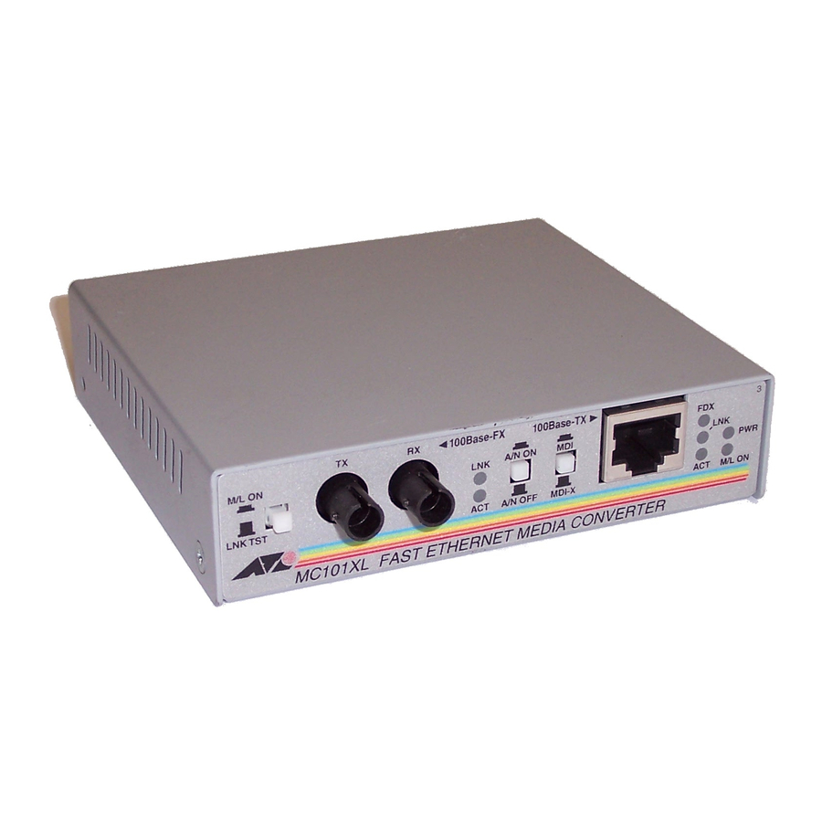
AT-MC100 Series Fast Ethernet Media Converters CLASS 1 100Base-FX 100Base-TX LASER PRODUCT DO NOT STARE INTO BEAM A/N ON M/L ON A/N OFF MDI-X LNK TST SINGLE MODE MC103SC/FS3 FAST ETHERNET MEDIA CONVERTER Figure 1 AT-MC103SC/FS3 Model... -
Page 12: Key Features
Maximum Distance Model Port 1 Port 2 Port 1 Port 2 (100Base-FX) (100Base-TX) (100Base-FX) (100Base-TX) AT-MC101XL RJ-45 2 km (1.2 mi) 100 m (328 ft) AT-MC102XL RJ-45 2 km (1.2 mi) 100 m (328 ft) AT-MC103XL RJ-45 15 km (9.3 mi) - Page 13 AT-MC100 Series Installation Guide Status LEDs Table 2 Status LEDs State Color Description Green A link has been established on the port. Green Data is being received on the port. Green Indicates that the unit is operating in full-duplex mode. Indicates that the unit is operating in half-duplex mode.
- Page 14 Link Test/MissingLink Button Link Test. MissingLink.
- Page 15 AT-MC100 Series Installation Guide Auto-negotiation Button Unit 1 Unit CLASS 1 100Base-FX 100Base-TX LASER PRODUCT DO NOT STARE INTO BEAM A/N ON A/N OFF MDI-X M/L ON LNK TST SINGLE MODE MC103SC/FS3 FAST ETHERNET MEDIA CONVERTER Media Converter 100Base-TX Switch 100Base-TX Repeater Figure 2 Example of a Duplex Mode Mismatch...
- Page 16 External AC/DC Power Adapter Figure 3 External AC/DC Power Adapter (North American version)
-
Page 17: Network Topologies
AT-MC100 Series Installation Guide Network Topologies 100 meters AT-8224XL AT-MC102XL STATUS RS-232 PORT ACTIVITY TERMINAL PORT 10BASE-T / 100BASE-T 10BASE-T / 100BASE-TX FAST ETHERNET SWITCH 100Base-FX 100Base-TX M/L ON A/N ON LNK TST A/N OFF MDI-X M/L ON MC102XL FAST ETHERNET MEDIA CONVERTER 2 kilometers Cable Legend 100 Mbps... -
Page 18: Installing The Media Converter
Installing the Media Converter Planning the Installation Cable Specifications Table 3 100Base-TX Twisted Pair Specifications Cable Type Maximum Distance Shielded or unshielded Category 5 or better 100 m (328 ft) - Page 19 Table 4 100Base-FX Fiber Optic Port Specifications (Full-duplex) Model Type of Fiber Optic Maximum Maximum Allowable Cable Distance Loss Budget AT-MC101XL 50/125 or 62.5/125 2 km (1.2 mi) 13 dB at 1310 nm micron multimode AT-MC102XL 50/125 or 62.5/125 2 km (1.2 mi)
- Page 20 Verifying the Package Contents Reviewing Safety Precautions...
- Page 21 AT-MC100 Series Installation Guide Installing the Media Converter...
- Page 22 12 V D C Figure 6 12 V DC Connector on Rear Panel...
- Page 23 AT-MC100 Series Installation Guide CLASS 1 100Base-FX 100Base-TX LASER PRODUCT DO NOT STARE INTO BEAM A/N ON A/N OFF MDI-X M/L ON LNK TST SINGLE MODE MC103SC/FS3 FAST ETHERNET MEDIA CONVERTER MDI-X Figure 7 MDI/MDI-X Switch Testing the Installation...
-
Page 25: Warranty Registration
AT-MC100 Series Installation Guide Warranty Registration Technical Specifications Physical Specifications Agency Certifications... - Page 26 Table 6 Fiber Optic Transmitter Model Fiber Fiber Optical Type Optic Frequency Launch Power (dBm) Diameter (nm) (microns) Max. Avg. Min. AT-MC101XL 50/125 1310 nm -14.0 -20.3 -22.5 62.5/125 1310 nm -14.0 -16.8 -19.0 AT-MC102XL AT-MC103XL 9/125 1310 nm -8.0 -11.5...
- Page 27 Table 7 Fiber Optic Receiver Model Fiber Fiber Optical Type Optic Frequency Receive Power (dBm) Diameter (nm) (microns) Min. Typical Saturation AT-MC101XL 50/125 or 1310 nm -31.8 -34.5 -14.0 62.5/125 AT-MC102XL AT-MC103XL 9/125 1310 nm -31.0 -31.0 -8.0 AT-MC103LH 9/125 1310 nm -35.0...
- Page 28 Minimum Average Minimum Maximum Type Power / Signal Distance Distance Link Loss Spec. Spec. Budget (dB) (dB) AT-MC101XL 50/125 13.00 18.70 2 km (1.2 mi) AT-MC102XL 62.5/125 16.80 22.50 2 km (1.2 mi) AT-MC103XL 9/125 SMF 16.00 19.50 15 km (9.4 mi)
- Page 29 AT-MC100 Series Installation Guide Table 9 Fiber Optic Loss Specifications (Benchmarks) Fiber Type Fiber Optic Optical Typical Worst Case Bandwidth Diameter Frequency Loss Loss Factor (Mhz-km) (microns) Factor (dB/km) (dB/km) 50/125 850 nm 3.00 3.50 50/125 1310 nm 1.00 1.50 62.5/125 850 nm 3.00...
-
Page 31: Translated Electrical Safety And Emission Information
Appendix A Translated Electrical Safety and Emission Information... - Page 33 AT-MC100 Series Installation Guide...
- Page 35 AT-MC100 Series Installation Guide...
- Page 37 AT-MC100 Series Installation Guide...
- Page 39 AT-MC100 Series Installation Guide...
- Page 41 AT-MC100 Series Installation Guide...
- Page 43 AT-MC100 Series Installation Guide...
-
Page 45: At-Mc100 Series Installation Guide Feedback
Appendix B AT-MC100 Series Installation Guide Feedback... -
Page 47: Technical Support Fax Order
Appendix C Technical Support Fax Order Incident Summary...
Need help?
Do you have a question about the AT-MC101XL and is the answer not in the manual?
Questions and answers