
Related Manuals for CYP CH-2603TX


Summary of Contents for CYP CH-2603TX
- Page 1 CH-2603TX HDMI/DP/VGA/USB to HDMI/HDBaseT Transmitter Operation Manual Operation Manual...
- Page 3 DISCLAIMERS The information in this manual has been carefully checked and is believed to be accurate. Cypress Technology assumes no responsibility for any infringements of patents or other rights of third parties which may result from its use. Cypress Technology assumes no responsibility for any inaccuracies that may be contained in this document.
- Page 4 SAFETY PRECAUTIONS Please read all instructions before attempting to unpack, install or operate this equipment and before connecting the power supply. Please keep the following in mind as you unpack and install this equipment: • Always follow basic safety precautions to reduce the risk of fire, electrical shock and injury to persons.
-
Page 5: Table Of Contents
CONTENTS 1. Introduction ............1 2. Applications .............1 3. Package Contents ..........2 4. System Requirements ........2 5. Features ............3 6. Operation Controls and Functions ....4 6.1 Front Panel ..........4 6.2 Rear Panel ..........6 6.3 IR Cable Pinouts ........8 6.4 RS-232 Pinout and Defaults ...... -
Page 6: Introduction
1. INTRODUCTION This HDBaseT 2.0 Transmitter is designed for use in environments needing a wide range of flexibility when it comes to inputs, outputs, and control. The three most common video input interfaces (HDMI, DisplayPort, and VGA w/stereo audio) are included, providing the ultimate in source compatibility and flexibility. -
Page 7: Package Contents
3. PACKAGE CONTENTS • 1×HDMI/DP/VGA/USB to HDMI/HDBaseT Transmitter • 1x3-pin terminal block • 1x5-pin terminal block • 1×3.5mm to IR Blaster Cable • 1×3.5mm to IR Extender Cable • 1×Shockproof Feet (Set of 4) • 1×Operation Manual 4. SYSTEM REQUIREMENTS •... -
Page 8: Features
5. FEATURES • HDMI and DisplayPort with 3D, & 4K video support (18Gbps) • HDCP 1.x & 2.2 compliant • HDBaseT 2.0 compatible • Selectable HDMI, DisplayPort, and VGA inputs • HDMI and DisplayPort inputs support resolutions up to 4K@60Hz (4:4:4, 8-bit) •... -
Page 9: Operation Controls And Functions
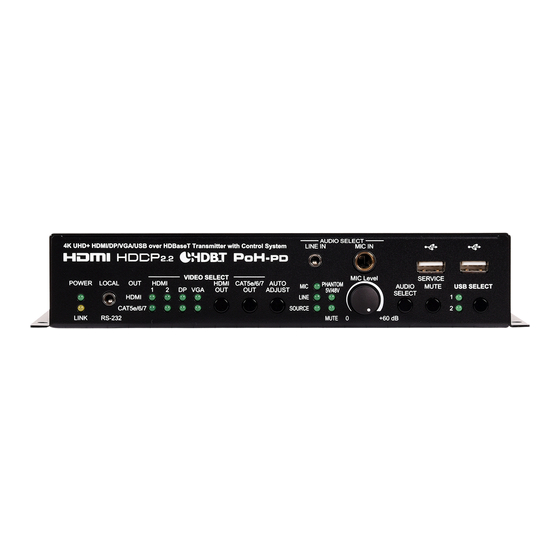
6. OPERATION CONTROLS AND FUNCTIONS 6.1 Front Panel AUDIO SELECT UHD + HDMI/DP/VGA/USB over HDBaseT Transmitter LINE IN MIC IN PoH- VIDEO SELECT MIC Level SERVICE POWER LOCAL HDMI HDMI CAT5e/6/7 AUTO PHANTOM AUDIO MUTE USB SELECT DP VGA ADJUST 5V/48V SELECT LINE... - Page 10 video source’s audio is currently active on the CAT5e/6/7 output. Note: When the mixer is active, more than one LED to be lit at the same time. Multiple LEDs indicate which audio sources are currently being combined. PHANTOM 5V/48V LED: This LED illuminates to indicate if phantom power (5V or 48V) is currently active on the microphone input.
-
Page 11: Rear Panel
6.2 Rear Panel TRIGGER IN ANALOG OUT USB 1 USB 2 BYPASS TX RX RS-232 HDMI 1 HDMI 2 VGA + L/R HDMI CAT5e/6/7 DC 24V HDMI 1 IN Port: Connect to HDMI source equipment such as a media player, game console, or set-top box. HDMI 2 IN Port: Connect to HDMI source equipment such as a media player, game console, or set-top box. - Page 12 USB Host Ports (Type B): Connect directly to a standard USB host such as a PC or laptop to extend their USB functionality to all currently connected USB devices. Note: Only one USB Host Port may be active at a time. IR IN Port: Connect to the provided IR Extender to receive IR control signals and extend them to devices connected to the other end of the HDBaseT connection.
-
Page 13: Ir Cable Pinouts
6.3 IR Cable Pinouts IR Blaster IR Extender Cable Cable Power Infrared Infrared Power Not Used Ground 6.4 RS-232 Pinout and Defaults Serial Port Default Settings Baud Rate 19200 Data Bits Parity Bits None Stop Bits Flow Control None 3-pin Terminal Block 3.5mm to DE-9 Adapter Cable... -
Page 14: Webgui Control
6.5 WebGUI Control • Device Discovery Please obtain the “Device Discovery” software from your authorized dealer and save it in a directory where you can easily find it. Connect the unit and your PC/Laptop to the same active network and execute the “Device Discovery” software. Click on “Find Devices on Network”... - Page 15 • WebGUI Overview After connecting to the WebGUI’s address in a web browser, the login screen will appear. Please enter the appropriate user name and password then click “Submit” to log in. Note: The default user name and password is “admin”. On the left side of the browser you will see the following menu tabs where all primary functions of the unit are controllable via the built in WebGUI.
-
Page 16: Video Select Tab
6.5.1 Video Select Tab This tab provides A/V routing control, auto switch controls, and I/O renaming options. To assign a new A/V route, please click the button of the Output you wish to route a source to on the left and then click on the button of the preferred Input port on the right. - Page 17 2) Auto Switch: Auto switching may be enabled or disabled individually for each Output. Click on the On/Off slider to toggle the behavior of the selected Output. This unit can store up to four routing presets. Presets can be utilized to store multiple different routing states in advance for rapid, hassle-free, recall.
-
Page 18: Edid Tab
6.5.2 EDID Tab This tab provides the option of six standard EDIDs, two sink sourced EDIDs and four customer uploaded User EDIDs that can be assigned to any or all of the HDMI/DisplayPort input ports. - Page 19 1) Customer EDID Settings: ■ Save Name: To modify the name of a User EDID, simply type the new name in the space provided and then click on the “Save Name” button to confirm the change. ■ Upload: To upload a User EDID, press the “Upload” button next to the User EDID slot you wish to upload into.
-
Page 20: Hdcp Tab
This unit provides the following 6 default EDIDs: Unit’s Default EDIDs FHD/2CH 1920×1080p@60Hz (148MHz) & LPCM 2.0 8-bit color FHD/MCH 1920×1080p@60Hz (148MHz) & LPCM 7.1 & 8-bit color Bitstream UHD/2CH 3840×2160p@30Hz (297MHz) & LPCM 2.0 Deep Color (8/10/12-bit) UHD/MCH 3840×2160p@30Hz (297MHz) & LPCM 7.1 &... -
Page 21: Usb Tab
on the right. The buttons will change color as you select them and the change in HDCP behavior will occur immediately across all selected Inputs. “Reference to Source” will make the input operate using the HDCP version required by the connected source. “Reference to Display”... -
Page 22: Audio Select Tab
6.5.5 Audio Select Tab This tab provides control over which audio is routed to the HDBaseT/ Analog audio outputs as well as control over audio mixing, analog I/O volume and the microphone’s phantom power voltage. Note: HDMI audio output is always a direct pass-through from the selected source and is not affected by the controls on this tab. - Page 23 Note: Source and Line volume controls are only enabled when the two sources are being mixed. ■ Source: Allows the adjustment of the currently selected video source’s audio volume when the mixer is active. The available adjustment range is -120 to +18 dB. Note: Only LPCM 2.0 is supported when the mixer is enabled.
-
Page 24: Trigger Tab
6.5.6 Trigger Tab This tab allows user to define the action taken set the definition of each Trigger pin. Click to check the drop down menu to select the config trigger define. 1) Set Trigger Input: Click on the dropdown next to each trigger number to assign a unit function or behavior to that trigger. -
Page 25: System Tab
6.5.7 System Tab This tab provides system information, network configuration options, system configuration resets, and firmware update functions. 1) System: ■ Web User Setting: This section provides a way to change the password for the Administrator account. Click on “Save” to confirm and activate any changes made to these settings. -
Page 26: Telnet Control
■ Web Login Timeout: Select the length of time to wait before logging the user out of the WebGUI due to inactivity. Available range is from 1 to 65535 minutes. Setting this to 0 will disable the inactivity timeout. ■ Firmware Upgrade: To update the unit's firmware, click the “Choose File”... -
Page 27: Rs-232 And Telnet Commands
6.7 RS-232 and Telnet Commands COMMAND Description and Parameters help Show the full command list. ? Show the full command list. help N1 Show help details about command N1. N1 = {Command} get model name Show the unit's model name. get fw ver... - Page 28 COMMAND Description and Parameters get ipconfig Show the unit's current IP configuration information. set ip addr N1 Set the unit's static IP address. N1 = X.X.X.X [X = 0 ~ 255] get ip addr Show the unit's current IP address. set netmask...
- Page 29 COMMAND Description and Parameters set webgui login timeout N1 Set the WebGUI inactivity timeout value. Available values for N1: [No timeout] 1 ~ 65535 [Timeout in minutes] get webgui login timeout Show the current WebGUI inactivity timeout value. set in N1 name N2 Set the name of the specified input.
- Page 30 COMMAND Description and Parameters get out N1 route Show the routing for the specified output. N1 = A ~ B [Output port] get in name list List all input names. get out name list List all output names. set out N1 auto mode N2 Set the automatic switching behavior of the specified output.
- Page 31 COMMAND Description and Parameters get in N1 interlace Show if the source connected to input N1 is interlaced or not. N1 = 1~4 [Input port] Possible response values: [Progressive] [Interlaced] get in N1 sync status Show the detected sync state for input N1. N1 = 1~4 [Input port] Possible response values:...
- Page 32 COMMAND Description and Parameters set all out route N1 Set the routing for all outputs to a single input. N1 = 1~4 [Input port] get all out route List the current input routing for all outputs. set out N1 cec data N2 Send a CEC command, as hex data, to the display connected to the specified output.
- Page 33 COMMAND Description and Parameters get preset N1 list Show the current routing saved within preset N1. N1 = 1~4 [Preset number] set route preset N1 name N2 Set the name of preset N1. N1 = 1 ~ 4 [Preset number] N2 = {Name} [16 characters max] get route preset N1 name...
- Page 34 COMMAND Description and Parameters get cat5e/6/7 audio mode Show the current audio content to routed to the HDBaseT/ Analog Audio outputs. set microphone mode N1 Set the location to use for manual control of the microphone volume. Available values for N1: [Front panel] [WebGUI] get microphone mode...
- Page 35 COMMAND Description and Parameters set analog output volume N1 Set the analog output volume. N1 = -103 ~ +24 [Volume in dB] get analog output volume Show the current analog output volume. set analog output mute N1 Enable or disable muting the analog audio output. Available values for N1: [Mute] [Unmute]...
- Page 36 COMMAND Description and Parameters [UHD MCH] [UHD+ 2CH] [UHD+ MCH] [User 1] [User 2] [User 3] [User 4] [Sink A] [Sink B] get in N1 edid Show the EDID currently being used on the specified input. (HDMI and DisplayPort only) N1 = 1 ~ 3 [Input port] get in edid list...
- Page 37 COMMAND Description and Parameters set user N1 edid data N2 Upload a new EDID (in HEX format) for use as the specified User EDID. N1 = 7 ~ 10 [User EDIDs] N2 = {EDID data} [Comma delimited hex pairs] get user N1 edid data Show the current contents of the specified User EDID as HEX data.
- Page 38 COMMAND Description and Parameters [Follow source] [Follow display] get in N1 hdcp mode Show the current HDCP behavior used by the specified input. (HDMI and DisplayPort only) N1 = 1 ~ 3 [Input port] get in N1 hdcp status Show the current HDCP status of the specified input. (HDMI and DisplayPort only) N1 = 1 ~ 3 [Input port]...
- Page 39 COMMAND Description and Parameters get out N1 hdcp ability Show the HDCP compliance level of the display device connected to the specified output. N1 = A ~ B [Output port] Possible response values: [No HDCP] [HDCP 1.x] [HDCP 2.2] [HDCP 1.x+2.2] get in N1 hdcp ability...
-
Page 40: Connection Diagram
7. CONNECTION DIAGRAM Trigger Control Laptop Keypad Macro Macro Media Player Macro Macro Macro Macro Macro Macro HDMI Audio Laptop Laptop Powered Monitor Speakers DisplayPort IR In & Out HDMI HDMI Router TRIGGER IN ANALOG OUT USB 1 USB 2 BYPASS TX RX RS-232... -
Page 41: Specifications
8. SPECIFICATIONS 8.1 Technical Specifications HDMI Bandwidth 18Gbps DisplayPort Bandwidth 21.6Gbps VGA Bandwidth 165MHz HDBaseT Bandwidth 10.2Gbps Input Ports 2×HDMI (Type-A) 1×DisplayPort 1×VGA (HD-15) 2×Unbalanced Stereo (3.5mm) 1×Microphone (6.35mm) Output Ports 1×HDBaseT (RJ-45) 1×HDMI (Type-A) 1×Balanced Stereo (5-pin Term. Block) Pass-through Ports 1×IR Extender (3.5mm) 1×IR Blaster (3.5mm) - Page 42 Power Supply 24V/3.75A DC (US/EU standards, CE/FCC/UL certified) ESD Protection (HBM) ±8kV (Air Discharge) ±4kV (Contact Discharge) Dimensions (W×H×D) 231.5mm×44mm×167mm [Case Only] 231.5mm×44mm×174mm [All Inclusive] Weight 1204g Chassis Material Metal (Steel) Chassis Color Black Operating Temperature 0˚C – 40˚C/32˚F – 104˚F Storage Temperature -20˚C –...
-
Page 43: Video Specifications
8.2 Video Specifications Input Output Supported Resolutions (Hz) HDMI HDMI HDBT 720×400p@70/85 640×480p@60/72/75/85 720×480i@60 720×480p@60 720×576i@50 ... - Page 44 Input Output Supported Resolutions (Hz) HDMI HDMI HDBT 1920×1200p@60RB 2560×1440p@60RB 2560×1600p@60RB 2048×1080p@24/25/30 2048×1080p@50/60 3840×2160p@24/25/30 ...
-
Page 45: Audio Specifications
8.3 Audio Specifications 8.3.1 Digital Audio HDMI & DisplayPort Input LPCM Max Channels 8 Channels Sampling Rate (kHz) 32, 44.1, 48, 88.2, 96, 176.4, 192 Bitstream Supported Formats Standard & High-Definition HDBaseT & HDMI Output LPCM Max Channels 8 Channels Sampling Rate (kHz) 32, 44.1, 48, 88.2, 96, 176.4, 192 Bitstream... - Page 46 Analog Output Max Audio Level 1Vrms THD+N < −80dB@0dBFS 1kHz (A-wt) > 80dB@0dBFS Frequency Response < ±1dB@20Hz~20kHz Crosstalk < −80dB@10kHz Impedance 470Ω Type Balanced...
-
Page 47: Cable Specifications
8.4 Cable Specifications 1080p 4K30 4K60 (4:4:4) (4:4:4) Cable Length 8-bit 12-bit 8-bit 8-bit High Speed HDMI Cable HDMI Input HDMI Output DisplayPort Cable DisplayPort Input Ethernet Cable Cat.5e/6 100m Cat.6a/7 100m 100m VGA Cable VGA Input 1.5m 1.5m Bandwidth Category Examples: •... -
Page 48: Hdbaset Features
8.5 HDBaseT Features HDBaseT Feature Set Transmitter Video & Audio Supported LAN Pass-through Supported Send power to Receiver Unsupported Accept power from Receiver Supported IR Pass-through Supported RS-232 Pass-through Supported... -
Page 49: Acronyms
9. ACRONYMS ACRONYM COMPLETE TERM Analog-to-Digital Converter ASCII American Standard Code for Information Interchange Audio/Video Cat.5e Enhanced Category 5 cable Cat.6 Category 6 cable Cat.6a Augmented Category 6 cable Cat.7 Category 7 cable Command-Line Interface Digital-to-Analog Converter DHCP Dynamic Host Configuration Protocol DisplayPort Digital Visual Interface EDID... - Page 50 ACRONYM COMPLETE TERM Powered Device Power over HDBaseT Power Sourcing Equipment Signal-to-Noise Ratio Transmission Control Protocol THD+N Total Harmonic Distortion plus Noise Ultra-High-Definition UHD+ Ultra-High-Definition Plus UHDTV Ultra-High-Definition Television Universal Serial Bus Video Graphics Array WUXGA (RB) Widescreen Ultra Extended Graphics Array (Reduced Blanking) Extended Graphics Array...
- Page 52 CYPRESS TECHNOLOGY CO., LTD. www.cypress.com.tw...
Need help?
Do you have a question about the CH-2603TX and is the answer not in the manual?
Questions and answers