Vega B63-48 Operating Instructions Manual
Overvoltage arresters
Hide thumbs
Also See for B63-48:
- Operating instructions manual (16 pages) ,
- Operating instructions manual (20 pages)
Table of Contents
Advertisement
Quick Links
Advertisement
Table of Contents

Related Manuals for Vega B63-48


Summary of Contents for Vega B63-48
- Page 1 Operating Instructions Overvoltage arresters B63-48, B63-32 Document ID: 33012...
-
Page 2: Table Of Contents
Wiring plan ............... 11 6 Maintenance and fault rectification Maintenance ..............12 Rectify faults ..............12 Instrument repair .............. 12 Dismounting Dismounting steps ............13 Disposal ................13 Supplement Technical data ..............14 Dimensions ..............15 Editing status: 2013-02-05 Overvoltage arresters • B63-48, B63-32... -
Page 3: About This Document
The dot set in front indicates a list with no implied sequence. → Action This arrow indicates a single action. Sequence Numbers set in front indicate successive steps in a procedure. Battery disposal This symbol indicates special information about the disposal of bat- teries and accumulators. Overvoltage arresters • B63-48, B63-32... -
Page 4: For Your Safety
During work on and with the device the required personal protective equipment must always be worn. Appropriate use B63-48, B63-32 are overvoltage arresters in two-wire technology for installation in VEGA level and pressure sensors. You can find detailed information on the application range in chapter "Product description". Warning about incorrect use Inappropriate or incorrect use of the instrument can give rise to application-specific hazards, e.g. vessel overfill or damage to system... -
Page 5: Safety Instructions For Ex Areas
That is why we have introduced an environment management system with the goal of continuously improving company environmental pro- tection. The environment management system is certified according to DIN EN ISO 14001. Please help us fulfill this obligation by observing the environmental instructions in this manual: • Chapter "Packaging, transport and storage" • Chapter "Disposal" Overvoltage arresters • B63-48, B63-32... -
Page 6: Product Description
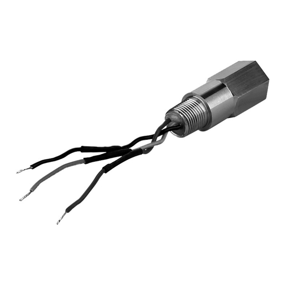
Principle of operation Application area The overvoltage arresters B63-48, B63-32 are completely enclosed in a stainless steel housing. They can be used for VEGA level and pres- sure sensors in two-wire technology. • Type B63-48 for 4 … 20 mA/HART sensors •... -
Page 7: Packaging, Transport And Storage
Protected against solar radiation • Avoiding mechanical shock and vibration • Storage and transport Storage and transport temperature see chapter "Supplement - temperature Technical data - Ambient conditions" • Relative humidity 20 … 85 % Overvoltage arresters • B63-48, B63-32... -
Page 8: Instructions For Installation
No further assembly is necessary. Caution: B63-48, B63-32 overvoltage arresters must not be used in a corrosive environment. The thread on the overvoltage arrester must correspond to the thread on the sensor housing. In order to maintain the enclosure rating of the sensor, PTFE gasket strip must be used. -
Page 9: Connecting To Power Supply
The B63-48, B63-32 exhibit a voltage resistance of 0.5 kV for one minute in the signal circuit with respect to the stainless steel housing, but not with respect to the green/yellow cable in the sensor circuit. - Page 10 12. Insert terminal block into its position by using the pliers. A me- chanical coding ensures the correct position 13. Screw cable gland into the thread of B63-48, B63-32, tighten compression nut. The seal ring must completely encircle the cable Display I ²...
-
Page 11: Wiring Plan
5 Connecting to power supply Wiring plan Wiring plan Display I ² C Fig. 3: Wiring plan, sensor side, example single chamber housing Connection cables of B63-48, B63-32, wire assignment see chart Terminals sensor Wire colour/Polarity Red (+) Black (-) Ground terminal Green/yellow Fig. -
Page 12: Maintenance And Fault Rectification
6 Maintenance and fault rectification Maintenance If the instrument is used properly, no special maintenance is required in normal operation. To ensure the function of B63-48, B63-32, we recommend a regular visual check at intervals of max. 1 year for: • secure mounting •... -
Page 13: Dismounting
WEEE directive. Correct disposal avoids negative effects on humans and the environ- ment and ensures recycling of useful raw materials. Materials: see chapter "Technical data" If you have no way to dispose of the old instrument properly, please contact us concerning return and disposal. Overvoltage arresters • B63-48, B63-32... -
Page 14: Supplement
For that reason the associated approval documents of these instruments have to be carefully noted. They are part of the delivery or can be downloaded under www.vega.com via "VEGA Tools" and "serial number search" as well as via "Downloads" and "Approvals". -
Page 15: Dimensions
8 Supplement Dimensions 76 mm 250 mm (2.99") (9.84") 56 mm (2.21") Fig. 5: Dimensions B63-48, B63-32 Thread M20 x 1.5 or ½ NPT, depending on order specification Overvoltage arresters • B63-48, B63-32... - Page 16 Subject to change without prior notice © VEGA Grieshaber KG, Schiltach/Germany 2013 VEGA Grieshaber KG Phone +49 7836 50-0 Am Hohenstein 113...
Need help?
Do you have a question about the B63-48 and is the answer not in the manual?
Questions and answers