Table of Contents
Advertisement
Quick Links
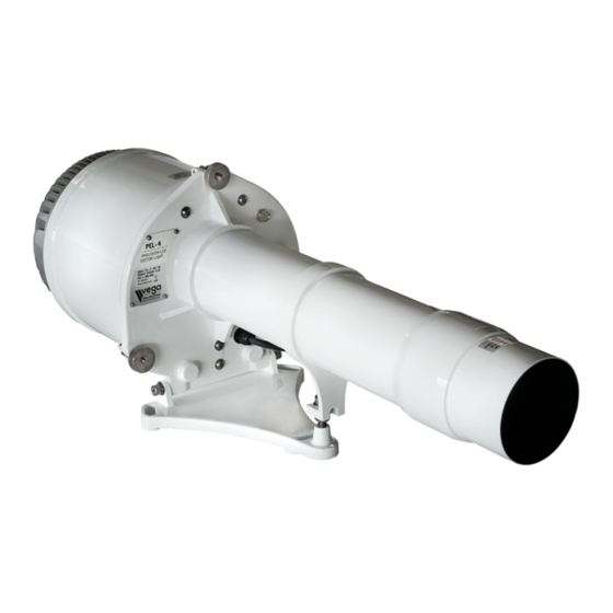
PEL-4 LED Precision Sector Light
All Horizontal Divergence Models
Installation, Operation and Programming Manual
Available colour range
Available models
Sector number & sub tenses
Software version:
Product version:
Manual version:
Date released:
IMPORTANT: If oscillating boundary has been installed, remove temporary packers
CAUTION: The PEL-4 is a source of bright light. Do not stare directly into the beam
from close range. Observe all warnings and guidelines in this instruction manual.
V E G A I N D U S T R I E S L I M I T E D
PEL-4 Product Manual
from inside of PEL-4 before first use.
Red, Green or White
3.5D, 5D, 10D
Custom
2.2.9+
3.00
1.06
August 2018
Advertisement
Table of Contents

Related Manuals for Vega PEL-4


Summary of Contents for Vega PEL-4
- Page 1 IMPORTANT: If oscillating boundary has been installed, remove temporary packers from inside of PEL-4 before first use. CAUTION: The PEL-4 is a source of bright light. Do not stare directly into the beam from close range. Observe all warnings and guidelines in this instruction manual.
- Page 2 Vega warrants that all products supplied are free from labour and material defects, and will repair or replace (at its option) the whole or any part of the products found to be faulty. Vega is not liable for any charge beyond the point of delivery, including installation, alignment or testing.
-
Page 3: Table Of Contents
Instruction Manual PEL-4 Precision LED Sector Light Vega Industries Ltd Aug 2018 Table of contents Introduction to the PEL-4 Precision LED Sector Light........5 Overview ........................5 Quick-start Guide ...................... 6 Automatic Flash Compensation ................7 PEL-4 Intensity Specification ..................7 Electrical Connection ..................... - Page 4 Instruction Manual PEL-4 Precision LED Sector Light Vega Industries Ltd Aug 2018 Remote Control Inputs .................... 27 9.2.1 Hard-wired Input Control Programming ............28 9.2.2 Hard-wired Input Level Settings Programming ..........28 Serial Remote Control Interface ................29 Serial Remote Control Mode Changes ..............30 Simultaneous Use of Remote Control Hardwired Inputs and Serial Interface ..
-
Page 5: Introduction To The Pel-4 Precision Led Sector Light
The PEL-4 has been designed with many features to allow the user to set up the operation for a specific site. These features are programmable using the Vega Remote infrared programmer (TVIR programmer ). -
Page 6: Quick-Start Guide
Vega-compatible sync source operating from the same power supply voltage as the PEL-4. To begin using the PEL-4, the power will need to be connected. The PEL-4 has been pre- programmed for the flash character, effective intensity, and any other features required at the time of sale. -
Page 7: Automatic Flash Compensation
The PEL-4 is programmed for the required colour (red/green) effective intensity in Candela. The white intensity will depend on the model of PEL-4. If the PEL-4 is a Uniform White model then the white intensity will be approximately the same as (but never less than) the programmed colour intensity. - Page 8 Example 2: How to calculate the PEL-4 flashing character intensity setting and to calculate the current consumption. For a PEL-4 set with an ISO 4s flash character and a desired white effective intensity of 100,000 candela, the table in Appendix B should be consulted twice: ...
-
Page 9: Electrical Connection
PEL-4 flash characters being synchronized. The start of the PEL-4 flash character can be delayed between 0 and 9.9 seconds from the sync edge should it be desirable to have a different start time to that of other beacons connected to the synchronising wire. - Page 10 Instruction Manual PEL-4 Precision LED Sector Light Vega Industries Ltd Aug 2018 Pin Colour Signal Direction Description Cyan Signal Ground Ground A polyfuse-protected common signal ground. Pink Beacon OK Output Grounded (positive sink) when PEL-4 is operating normally with no alarm condition.
-
Page 11: Mounting And Alignment
Aug 2018 MOUNTING AND ALIGNMENT Mounting A typical PEL-4 mounting plate is shown in the following figure. The mounting holes are designed for M12 or half-inch bolts at 120 degree-spacing on a 286mm Pitch Circle Diameter (PCD). PEL-4 5D & 10D Models’ Mounting Bracket – Plan View PEL-4 3.5D Model’s Mounting Brackets –... -
Page 12: Alignment
The PEL-4 mounting bracket provides a few degrees of horizontal angle adjustment prior to tightening the M12 bolts through it. The PEL-4 includes an M12 elevation adjustment screw beneath the barrel, as shown in the following diagrams. PEL-4 Precision LED Sector Light Page 12 of 69 Manual Version V1.06... -
Page 13: Programming
PEL-4 mainframe (indicated by the red markings in the following diagrams). For best results when programming, direct the TVIR programmer at this part of the PEL-4. Refer to Appendix A for operating the TVIR Programmer. -
Page 14: Programming Syntax
Operation 7 Read settings Operation 9 The FEATURE parameter represents the feature of the PEL-4 to be read or written such as flash character or intensity. The VALUE parameter is the new value to set the selected FEATURE to. For example, the sequence 9 8 reads the low battery threshold (operation 9 = read setting, feature 8 = low battery threshold). -
Page 15: If The Pel-4 Will Not Enter Programming Mode
If the PEL-4 will not enter Programming Mode If you find the PEL-4 will not enter the programming mode, it could be caused by several reasons such as: The battery in the TVIR Programmer is missing, or the plastic battery insulator has not been removed, or the battery has low voltage. - Page 16 Press the red standby button for 5 indicate it has entered programming mode seconds 2. Enter the programming sequence for The PEL-4 will flash once each time a key the Operation Mode (15003) on the programmer is operated. When the sequence is completed the command will be rejected and an error indicated by 3 quick flashes.
-
Page 17: Deciding Which Settings Are Required
Deciding which Settings are required Since the PEL-4 is delivered from the factory with operator-specified settings, it is unlikely to be necessary to reprogram any settings. The “Read Settings” feature can be used to note the values already programmed. -
Page 18: Normal, Automatic Operating Mode
NORMAL, AUTOMATIC OPERATING MODE The operation mode setting is the master mode setting of the PEL-4. It controls whether the PEL-4 is operational or in storage mode and how the PEL-4 responds to detected fault conditions. There are two normal, automatic operation modes: ... -
Page 19: Custom Flash Character
To program the custom character, the details of the on and off periods of the flash character has to be recorded in the PEL-4 and then the flash character ‘999’ has to be programmed (see the previous section for this last step). -
Page 20: Night & Day Intensity Settings
The default construction of the PEL-4 places the photocell inside the rear cover, obscuring it from the intense light output of the PEL-4. It is important to ensure that the rear cover is not obscured from daylight if automatic day/night operation is required. The PEL-4 will transition from night to day operation, or vice versa, after three consecutive, filtered daylight samples agree that the user-programmed Lux threshold has been reached. -
Page 21: Synchronising Options
Each PEL-4 can be set to be a sync master or sync slave. As a sync slave, the PEL-4 will not generate sync pulses and will only turn on if sync pulses are received. A PEL-4 set to be a sync master (the default) will generate a sync pulse at the start of the flash character. -
Page 22: Battery Thresholds
999 will disable this function of protecting the battery. Note, however that the PEL-4 will always turn off when the input voltage is either too low for it to function correctly, or below the input current demand of the PEL-4’s design specification. - Page 23 Instruction Manual PEL-4 Precision LED Sector Light Vega Industries Ltd Aug 2018 The input voltage value is provided in tenths of a volt. For example, a read-back of ‘120’ means 12.0V was detected. An error of +/-2% in this reading is typical.
-
Page 24: Setting A Security Pin Number
Value =XXX =PIN number If the entered PIN number is correct, the PEL-4 will flash back the PIN number using a series of flashes and, during the current TVIR programming session (only), subsequent programming commands will be accepted. Entering an incorrect PIN will cause the PEL-4 to return an error flash code. Multiple attempts can be made without penalty to enter the correct PIN. -
Page 25: Flash Character Modes
Flash Compensation Modes The PEL-4 is capable of generating several different flash characteristics. The IALA E-200- 4 2017 flash compensation algorithm is enabled by default. Additionally, a peak intensity during flash mode is available in which no flash compensation is applied. Lastly, an historic IALA E-200-4 2008 flash compensation algorithm can also be programmed. -
Page 26: Peak Intensity During The Flash Mode
Peak Intensity During the Flash Mode No flash compensation is applied in this mode. The programmed day or night intensity is directly output from the PEL-4 during the flash on (a.k.a. peak) period of the flash character. Peak intensity during flash mode can be selected as follows:... -
Page 27: Remote Control Operation
PEL-4 Precision LED Sector Light Vega Industries Ltd Aug 2018 REMOTE CONTROL OPERATION The PEL-4 includes an extensive set of remote control features. These features are compatible with many other advanced PEL-4 functions. Enabling Remote Control Operation The remote control features must be enabled using the master operation mode programming sequence. -
Page 28: Hard-Wired Input Control Programming
7-4-XYZ remote control mode command contains three separate digits controlling separate parts of the remote control setup: Digit X defines the input active polarity (the PEL-4 only supports 1 = high active); Digit Y defines whether an internal pull-up/down is enabled (the PEL-4 only supports 1 = pull-down enabled);... -
Page 29: Serial Remote Control Interface
The serial interface commands work in a differential mode to the current PEL-4 state. If a new serial command is received that requires a change in state compared to the existing PEL-4 state, then a change of state is scheduled and will occur in the next one to two seconds. -
Page 30: Serial Remote Control Mode Changes
If necessary, repeated site visits to manually change the PEL-4 state can be made until the serial communications system is repaired. Until new serial <RON> commands are received by the PEL-4, it will remain in the state manually set by the On/Off input switch. - Page 31 Instruction Manual PEL-4 Precision LED Sector Light Vega Industries Ltd Aug 2018 PEL-4 Precision LED Sector Light Page 31 of 69 Manual Version V1.06...
-
Page 32: 10.0 Routine Maintenance
4. Rinse off with clean water. Do not use any form of abrasive cloth or cleaner on any part of the PEL. Regular opening of the PEL-4’s rear cover is not recommended. There are no user- serviceable parts inside. Do not touch, rub or clean the LED. The LED can be hot and extremely bright. -
Page 33: Appendix A Programming Table
The operating mode and other settings are indicated on the associated PEL-4 test sheet. The operator has full control of the PEL-4’s operational mode and all settings can be altered as described in the following tables. For most TVIR commands in the following table, the corresponding serial interface command or related serial commands are shown in font. - Page 34 Instruction Manual PEL-4 Precision LED Sector Light Vega Industries Ltd Aug 2018 Generic TVIR Programming Commands Operation Feature Value Flash Character: In single character mode the default character is accessed here and is used for both night and day operation.
- Page 35 Instruction Manual PEL-4 Precision LED Sector Light Vega Industries Ltd Aug 2018 Generic TVIR Programming Commands Operation Feature Value Normal, Automatic Operation Modes 001 – Normal Failsafe 002 – Normal Best Effort (Default) Remote Control Modes 003 – Remote Failsafe Mode 004 –...
- Page 36 Instruction Manual PEL-4 Precision LED Sector Light Vega Industries Ltd Aug 2018 Generic TVIR Programming Commands Operation Feature Value Interface Mode (Master Projector): 00X, where X is: 0 – Disable IRDA and RS232, No Monitoring 1 – Enable IRDA, No Monitoring 2 –...
- Page 37 Instruction Manual PEL-4 Precision LED Sector Light Vega Industries Ltd Aug 2018 Generic TVIR Programming Commands Operation Feature Value 0YY– Continue number of cycles (002-099) 7 = Additional Sync after loss of sync (disables ‘Off on sync low’ Options mode).
- Page 38 Instruction Manual PEL-4 Precision LED Sector Light Vega Industries Ltd Aug 2018 Generic TVIR Programming Commands Operation Feature Value 0 = Software version Version Y.Y.Y (e.g. 2.1.0) <VER>?/ 1 – Battery voltage YY.Y Volts (e.g. 11.7 volts) Last voltage <BAT>?/ prior to entering programming mode 2 –...
- Page 39 Instruction Manual PEL-4 Precision LED Sector Light Vega Industries Ltd Aug 2018 Generic TVIR Programming Commands Operation Feature Value XXX (000 clears the PIN) If the new PIN code is non-zero then it must 1-Set PIN be entered using the 7-7-XXX command <PIN>XXX/...
- Page 40 Instruction Manual PEL-4 Precision LED Sector Light Vega Industries Ltd Aug 2018 Generic TVIR Programming Commands Operation Feature Value XYZ – defined as above in command 3 – Read Flash Mode 7-2-XYZ <FOM>?/ <FCM>?/ Sets remote control mode functions and pull-up/pull-down state and polarity sensitivity of the dataport inputs.
-
Page 41: Appendix A.2 Remote Control Input Level Settings
Instruction Manual PEL-4 Precision LED Sector Light Vega Industries Ltd Aug 2018 Appendix A.2 Remote Control Input Level Settings The following table describes the four combinatorial options for remote control of the PEL- 4. There are two separate remote control inputs: On/Off and Day/Night. Each control input is either enabled (shown with a ... -
Page 42: Appendix A.3 Factory Default Reset Commands
Instruction Manual PEL-4 Precision LED Sector Light Vega Industries Ltd Aug 2018 Appendix A.3 Factory Default Reset Commands The following commands reset multiple beacon settings to nominal values. Several alternative commands are provided for convenience, allowing a beacon to be set to one of several nominal operational types. - Page 43 Instruction Manual PEL-4 Precision LED Sector Light Vega Industries Ltd Aug 2018 Factory Default Reset Commands (continued) Programming Reset Reset Effects Code Variant 1-5-997 Oscillating Default (Night & Day) Fixed Character (1-0-000) Boundary Night intensity is set to maximum intensity <FDF>997/...
-
Page 44: Appendix B Intensity Settings And Currents
Instruction Manual PEL-4 Precision LED Sector Light Vega Industries Ltd Aug 2018 APPENDIX B INTENSITY SETTINGS AND CURRENTS Refer to the end of this appendix for the table legend and notes. Appendix B.1 3.5D Models PEL-4 3D5 Uniform White Build 435CV2ND30UW480... - Page 45 Instruction Manual PEL-4 Precision LED Sector Light Vega Industries Ltd Aug 2018 PEL-4 3D5 Intense White Build 435CV2ND00UW480 Characterisation 3520 INTENSE WHITE RED & GREEN Jun-18 Prog 10,000 5,000 Night 10,000 5,000 Night Code White Intensity Current Current Cd/m2 Cd/m2...
-
Page 46: Appendix B.2 5D Models
Instruction Manual PEL-4 Precision LED Sector Light Vega Industries Ltd Aug 2018 Appendix B.2 5D Models PEL-4 5D Uniform White Build 405CV2ND30UW480 Characterisation 0520 RED, GREEN Mar-17 WHITE, Prog 10,000 5,000 Night Code Intensity Current Current Cd/m2 Cd/m2 Range (six... - Page 47 Instruction Manual PEL-4 Precision LED Sector Light Vega Industries Ltd Aug 2018 PEL-4 5D Intense White Build 405CV2ND00UW480 Characterisation 0520 INTENSE WHITE RED & GREEN Mar-17 Prog 10,000 5,000 Night 10,000 5,000 Night Code White Intensity Current Current Cd/m2 Cd/m2...
-
Page 48: Appendix B.3 10D Models
Instruction Manual PEL-4 Precision LED Sector Light Vega Industries Ltd Aug 2018 Appendix B.3 10D Models PEL-4 10D Uniform White Build 410CV2ND30UW480 Characterisation 1020 RED, GREEN Mar-17 WHITE, Prog 10,000 5,000 Night Code Intensity Current Current Cd/m2 Cd/m2 Range (six... - Page 49 *** In an Oscillating Boundary PEL-4, the ‘On’ current is drawn when the PEL-4 is on and the ‘Off’ current is drawn when the PEL-4 is off. In a Fixed Boundary PEL-4 this current is zero in the on and off states.
-
Page 50: Appendix Cpel-4 Dimensions By Model
Instruction Manual PEL-4 Precision LED Sector Light Vega Industries Ltd Aug 2018 APPENDIX C PEL-4 DIMENSIONS BY MODEL PEL-4 3.5D General Assembly Drawing PEL-4 Precision LED Sector Light Page 50 of 69 Manual Version V1.06... - Page 51 Instruction Manual PEL-4 Precision LED Sector Light Vega Industries Ltd Aug 2018 PEL-4 5D General Assembly Drawing PEL-4 Precision LED Sector Light Page 51 of 69 Manual Version V1.06...
- Page 52 Instruction Manual PEL-4 Precision LED Sector Light Vega Industries Ltd Aug 2018 PEL-4 10D General Assembly Drawing PEL-4 Precision LED Sector Light Page 52 of 69 Manual Version V1.06...
-
Page 53: Appendix D Specifications Of Pel-4
Instruction Manual PEL-4 Precision LED Sector Light Vega Industries Ltd Aug 2018 APPENDIX D SPECIFICATIONS OF PEL-4 Optics Light Source High-Intensity Light-Emitting Diode Colours Available Red, Green, White Intensity See Appendix B Colour Boundary Precision PEL-4: typ. 1’ of arc (0.017 degrees) Effective intensity settings Programmable in 1 Candela steps for the ranges shown in Appendix B. - Page 54 Instruction Manual PEL-4 Precision LED Sector Light Vega Industries Ltd Aug 2018 TVIR Programmer: Remote02 Coding Scheme: RC5 code with centre frequency 36.7 kHz Dimensions: 87mm x 41mm x 6.5mm Weight: 18gms Power Supply: 1 x 3V lithium coin cell battery, CR2025 type...
-
Page 55: Appendix Eflash Character Table With Programming Codes
Instruction Manual PEL-4 Precision LED Sector Light Vega Industries Ltd Aug 2018 APPENDIX E FLASH CHARACTER TABLE WITH PROGRAMMING CODES FIXED DETAIL 304 FL 2s 0.2 0.2s, 1.8s 000 Fixed FLASH DETAIL 305 FL 2s 0.3 0.3s, 1.7s 306 FL 2s 0.4 0.4s, 1.6s... - Page 56 Instruction Manual PEL-4 Precision LED Sector Light Vega Industries Ltd Aug 2018 346 FL 10s 0.2 0.2s, 9.8s 432 Fl(2) 12s 0.5 1.0 0.5s, 1s, 0.5s, 10s 347 FL 10s 0.3 0.3s, 9.7s 433 Fl(2) 12s 1.0 2.0 1s, 2s, 1s, 8s 348 FL 10s 0.5...
- Page 57 Instruction Manual PEL-4 Precision LED Sector Light Vega Industries Ltd Aug 2018 475 Fl(2+1) 12s 0.4s, 4.6s, 0.4s, 4.6s, 0.4s, 1s, 1s, 1s, 4s, 1s, 4s 620 Q(3) 30s 0.4 19.6s 476 Fl(2+1) 15s 0.3s, 0.7s, 0.3s, 0.7s, 0.3s, 1s, 2s, 1s, 5s, 1s, 5s 621 Q(4) 6s 0.3...
- Page 58 Instruction Manual PEL-4 Precision LED Sector Light Vega Industries Ltd Aug 2018 816 MO(U) 0.55s, 0.35s, 0.55s, 0.35s, 933 Q92 0.3s, 0.35s 0.55 1.45s, 11.75s 817 MO(U) 0.6s, 0.3s, 0.6s, 0.3s, 1.4s, 934 Q44 0.3s, 1.05s 0.60 11.8s 818 MO(U) 15s 0.7 0.7s, 0.5s, 0.7s, 0.5s, 1.9s,...
-
Page 59: Appendix F Serial Interface Commands
Aug 2018 APPENDIX F SERIAL INTERFACE COMMANDS The PEL-4 offers a serial interface control and monitoring capability. Many of these commands can be found in Appendix A as annotations to their related TVIR commands. Any command can be turned into a query by inserting a question-mark character, ‘?’... - Page 60 Instruction Manual PEL-4 Precision LED Sector Light Vega Industries Ltd Aug 2018 Command Command Valid Parameter Acts Description (Pseudo- or Query Range & Unit Immediately XML Tag) Name or Requires Restart <DFI>B/ Display B = 0: Display Restart Turns off the red LED...
- Page 61 Instruction Manual PEL-4 Precision LED Sector Light Vega Industries Ltd Aug 2018 Command Command Valid Parameter Acts Description (Pseudo- or Query Range & Unit Immediately XML Tag) Name or Requires Restart <SPC>…/ Special A sequence of Restart Defines the manually-...
- Page 62 Instruction Manual PEL-4 Precision LED Sector Light Vega Industries Ltd Aug 2018 Command Command Valid Parameter Acts Description (Pseudo- or Query Range & Unit Immediately XML Tag) Name or Requires Restart <ODS>B/ On-demand B = 0: Disables Restart When set the PEL-4...
- Page 63 Instruction Manual PEL-4 Precision LED Sector Light Vega Industries Ltd Aug 2018 Command Command Valid Parameter Acts Description (Pseudo- or Query Range & Unit Immediately XML Tag) Name or Requires Restart <GPE>B/ GPS enabled B = 0: Disable Restart When set to 1, GPS...
- Page 64 Instruction Manual PEL-4 Precision LED Sector Light Vega Industries Ltd Aug 2018 Command Command Valid Parameter Acts Description (Pseudo- or Query Range & Unit Immediately XML Tag) Name or Requires Restart <RFF>B/ Remote B = 0: Fixed Immediate Selects the programmed...
- Page 65 Instruction Manual PEL-4 Precision LED Sector Light Vega Industries Ltd Aug 2018 Command Command Valid Parameter Acts Description (Pseudo- or Query Range & Unit Immediately XML Tag) Name or Requires Restart <TYR>XY/ Projector Bus X = total Restart Sets the master-slave Addressing projectors;...
- Page 66 Instruction Manual PEL-4 Precision LED Sector Light Vega Industries Ltd Aug 2018 Command Command Valid Parameter Acts Description (Pseudo- or Query Range & Unit Immediately XML Tag) Name or Requires Restart <ERR>B/ Error logging B: defines Immediate Reads back the error log...
- Page 67 Instruction Manual PEL-4 Precision LED Sector Light Vega Industries Ltd Aug 2018 Command Command Valid Parameter Acts Description (Pseudo- or Query Range & Unit Immediately XML Tag) Name or Requires Restart <CLE>/ Clears None or any Immediate Clears all logged...
- Page 68 Instruction Manual PEL-4 Precision LED Sector Light Vega Industries Ltd Aug 2018 Command Command Valid Parameter Acts Description (Pseudo- or Query Range & Unit Immediately XML Tag) Name or Requires Restart <LDI>?/ Load Current ‘?’ only Immediate Outputs the average load current (i.e.
- Page 69 Instruction Manual PEL-4 Precision LED Sector Light Vega Industries Ltd Aug 2018 Command Command Valid Parameter Acts Description (Pseudo- or Query Range & Unit Immediately XML Tag) Name or Requires Restart <DAY>?/ Day State ‘?’ only Immediate A ‘1’ value indicates that the beacon is in day mode.
Need help?
Do you have a question about the PEL-4 and is the answer not in the manual?
Questions and answers