Table of Contents
Advertisement
Quick Links
Advertisement
Table of Contents

Related Manuals for Vega SHLD 2


Summary of Contents for Vega SHLD 2
- Page 1 Operating Instructions ® SHLD 2 Source Holder Document ID: 63138 Radiometric...
-
Page 3: Table Of Contents
Table of Contents Revision Table ..............5 About this Document ............7 Intended Use................ 7 Targeted Group..............8 Explanation of Symbols ............8 For Your Safety ..............11 General Safety ..............11 Radiation Safety..............11 Radiation Safety Officer ..............12 Appropriate Use ..............12 Incorrect Use.............. - Page 4 Shutter.................... 16 Configuration ..............16 Versions ..................19 Application Area ..............20 Maximum Activity of Source ............21 Packaging, Transport & Storage ........21 Storage and Transport Temperature ..........22 Receiving the Equipment........... 22 Mounting ................25 General................25 Mounting Checklist ............25 Mounting with a Crane...............
- Page 5 Commission the Source Holder ......... 41 Commissioning Call Checklist............41 Normal Operation............... 42 Source Holder Installation Requirements........42 Preliminary Survey ................43 Perform a Leak Test................43 Radiation Survey after Installation ..........44 Shutter Operation Test (on applicable source holders)....44 Shutter (ON/OFF) Mechanism (required every six months)....45 Special Conditions .............
- Page 6 Troubleshooting..............60 Correcting Issues............... 61 Emergency Measures ..............61 Dismounting ............... 63 De-commission the Source Holder ........63 Dismount or Removal Requirements ..........63 Transfer Ownership or Disposal ........65 Source Disposal ................65 Supplemental Information ..........67 Technical Data..............67 General Data ..................
-
Page 7: Revision Table
Date Initial release 200110 This document contains proprietary information of VEGA Americas, Inc. It shall not be reproduced in whole or in part, in any form, without the expressed written permission of VEGA Americas, Inc. The material in this document is provided for informational purposes and is subject to change without notice. - Page 8 NOTES 63138-US-200110...
-
Page 9: About This Document
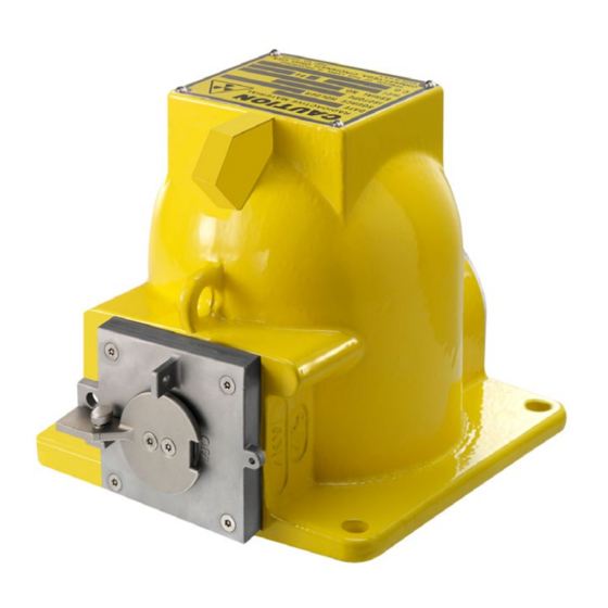
The instructions in this guide are written for qualified and well- trained personnel. Make sure you read and understand all the instructions and safety guidelines in the Operating Instructions NOTE before operating this equipment. Keep this manual accessible in the immediate vicinity of the device. SHLD 2 Figure 1.1 63138-US-200110... -
Page 10: Targeted Group
1.2 Targeted Group The Operating Instructions are provided for trained personnel. The manual not only provides instructions for the setup and operation of the instruments, but also specifically address topics and procedures required by an intermediate level user such as the following: •... - Page 11 Ex Applications Indicates special instructions for Ex applications. Radiation Introduces information concerning radioactive materials or radiation safety. Bulleted list • Indicates a list of items with no intended or implied sequence Steps or Sequence Identifies successive steps in a procedure 63138-US-200110...
- Page 12 NOTES 63138-US-200110...
-
Page 13: For Your Safety
For Your Safety 2.1 General Safety Make sure you read and understand all the instructions and safety guidelines in the Installation and Operation Guide before operating the source holder. The instructions in this guide are written for qualified and trained personnel. Your equipment requires strict observance of standard regulations and guidelines. -
Page 14: Radiation Safety Officer
2.3 Appropriate Use When in operating mode, the source container SHLD 2 described in this document contains a radioactive source for radiometric level, interface, switching and density measurement. The source container shields the radiation from the surroundings and only allows it to exit in the direction of measurement. -
Page 15: Installation And Operation In Us & Canada
With these instruments, you must observe the corresponding approval documents. These documents are part of the scope of delivery or you download the documents from "www.vega.com", "Instrument search (serial number)" as well as using "Downloads" and "Approvals". The operator must check the suitability of the radiometric measuring principle as well as of the instrument for use in hazardous areas by consulting the applicable national regulations. -
Page 16: Applications
ODH/NRC - Ohio Department of Health and Nuclear Regulatory Commission Standards The SHLD 2 source holders is regulated by the U.S. Nuclear Regulatory Commission (NRC). Compliance certificates are issued by the State of Ohio under an agreement with the NRC. -
Page 17: Product Description
Product Description 3.1 Principle of Operation The SHLD 2 is used to position and protect a radioactive source near a process vessel, pipe or on a conveyor belt/spiral conveyor. Radiation from the source is directed through the process by an integral collimator. A radiation detector placed opposite the source holder measures radiation fluctuations caused by process condition changes. -
Page 18: Source Holder
You must not remove the stainless steel Caution-Radioactive Material Label. The label must remain clean of process material, unaltered, and legible for the duration of the source holder’s use. NOTE Source Holder The source holder is constructed from either stainless steel or low carbon steel with a polyester powder coating designed to perform the following: •... - Page 19 • The serial number allows you to access the delivery data of the instrument via "www.vega.com", "VEGA Tools" and "Instrument search". The local dose rate on the type label at a defined distance is safety-oriented and includes production-related fluctuations of the emitters and tolerances of the measuring devices.
- Page 20 Type Label Figure 3.2 A. Type Label - Source B. Type Label - Source Holder 1. Source: Cs-137 2. Serial Number of Source Capsule (for traceability of source) 3. Activity of Sources in MBq and mCi or GBq and mCi 4.
-
Page 21: Versions
Versions There are several versions of the SHLD 2 available with different options. Apart from the manual versions, there are also versions with pneumatic switchover. SHLD 2 Versions Figure 3.3 1. Overview 2. Standard Version 3. With Position Switch 4. With Interlock Safety Switch 5. -
Page 22: Application Area
The SHLD 2 is a source holder designed for shielding radioactive sources such as Cs-137. The radioactive source in the source container emits gamma rays. The SHLD 2 is mounted on the vessel, the pipeline, or on a conveyor belt/spiral conveyor directly opposite the sensor. -
Page 23: Maximum Activity Of Source
Maximum Activity of Source The following table states the maximum activity of the sources. Production- related fluctuations of the radiation activity and tolerances of the measuring instruments are not taken into account. Cs-137 Maximum Cs-137 185 GBq (5 Ci) for 50 uSv@305mm (5mR/hr@12") Activity 500 mCi for point sources 500 mCi total and 50 mCi/ft for multi-point sources... -
Page 24: Storage And Transport Temperature
Any claims against VEGA for shortages, errors in shipment, etc., must occur within 30 days of receipt of the shipment. If you must return the equipment to VEGA, make sure to contact your VEGA representative. NOTE... - Page 25 Make certain the shutter of the source holder is closed and locked. If you find the shutter is open, close it immediately and secure it. CAUTION Compare the shipment against the packing slip to make certain you received your complete order. If you are not installing or mounting the source holder immediately, find a storage area that is secure and isolated.
- Page 26 NOTES 63138-US-200110...
-
Page 27: Mounting
Check that the mounting position of the source holder complies with manufacturer's engineering drawings and specifications. (See certified correct drawings or contact VEGA Americas.) Ensure adequate clearance to operate the shutter or cable mechanism. Consider in advance any high temperature or corrosive environmental conditions. -
Page 28: Mounting With A Crane
Avoid risk to other people by taking suitable measures such as a safety fence, when mounting the source holder. • Depending on the version, the center of gravity of the SHLD 2 can vary. Keep this in mind during crane transport on the lug. Mounting with a Crane Check the hoisting equipment for sufficient lifting capacity, which is approximately 330 lbs(150 kg). -
Page 29: Mounting Orientation
The radiation must be directed exactly towards the detector mounted on the opposite side. The source holder SHLD 2 should be mounted as close as possible to the vessel. However, with large measuring ranges and small vessel diameters, a gap can often is not avoidable. -
Page 30: Mass Flow Orientation
Make certain the radiation is directed exactly towards the detector mounted on the opposite side. Mount the source holder SHLD 2 on the measuring frame (optional). There are large spacings and gaps between the measuring frame and conveyor belt. -
Page 31: Point Level Orientation
To make sure the beam is horizontal, you have to mount the source holder so that the implied opening of the exit channel is in a horizontal position. Mount the SHLD 2 as close as possible to the vessel. With large measuring ranges and small vessel diameters, a gap may exist. -
Page 32: Density Orientation
Find the required mounting accessories in the chapter "Supplemental-Info". Mount the source holder SHLD 2 as close as possible to the vessel. However, with large measuring ranges and small vessel diameters, a gap can often is not avoidable. -
Page 33: Vertical Pipeline, 30° Inclined, Diameter 1.97
Vertical Pipeline, 30° Inclined, diameter 1.97…3.94 in (50…100 mm) For small pipe diameters 1.97 … 3.94 in (50 … 100 mm), a diagonal radiation path is recommended. The distance of the beam through the medium is thus longer and an improved measuring effect is achieved. In such cases, the optional lead shielding for the detector is recommended to avoid influence from any secondary radiation sources. -
Page 34: Vertical Pipeline, Diameter 1.97
Mount the radiometric sensor either horizontally or vertically. Vertical Pipeline, 30°, diameter 1.97 … 23.62 in (50 … 600 mm) Figure 4.5 1. Source Holder (SHLD 2) 2. Radiometric Sensor (MINITRAC) 3. Mounting horizontally, at right angles to container 4. -
Page 35: Avoiding Stray Radiation - Vertical Pipeline, Diameter 1.97
Vertical Pipeline with Horizontal Sensor 1.97…23.62 in (50…600 mm) Figure 4.6 1. Source Holder (SHLD 2) 2. Radiometric Sensor (MINITRAC) 3. Mounting horizontally, at right angles to container 4. Mounting Bracket... -
Page 36: Horizontal Pipeline
Horizontal pipeline On a horizontal pipeline, the radiation should be directed horizontally to avoid interference from air pockets. Measurement Setup on Horizontal Pipeline Figure 4.7 1. Source holder (SHLD 2) 2. Radiated area 3. Detector (MINITRAC) 63138-US-200110... -
Page 37: Screw Locking Mechanism
Screw Locking Mechanism The source holder must be integrated in the potential equalization of the system. To ensure a good electrical contact between the source holder and the mounting bracket, you must use the supplied lock washers to the following illustration. Use the prescribed torque for the mounting screws (M10). -
Page 38: Mounting Facilities
Mounting Facilities You can also mount the source container on a mounting plate provided by the customer or on an L-Profile. Mounting Facility Supplied by Customer - Hole Pattern Figure 4.9 1. Mounting Plate 2. L-profiles Installation Control Measurement of Local Dose Rate After mounting, or as soon as the radioactive emitter is mounted in the source holder, you must measure the local dose rate in the area of the source holder and the detector. -
Page 39: Location
Location At the time you ordered your equipment, VEGA sized the source holder for optimal performance for the designated application. If the location of the equipment has changed or is different from the original order, notify VEGA before installing the equipment. -
Page 40: Source Interference
Source Interference When multiple adjacent pipes, vessels, or conveyors have radiometric gauges, you must consider the orientation of the source beams so each gauge senses radiation only from its appropriate source. Maximize the distance between the source holders when mounting them on adjacent vessels. Make sure to maintain the appropriate source to detector distance as illustrated in Figure 4.10. -
Page 41: Ambient Temperature
You may use the source holder in continuous ambient temperature conditions. The SHLD 2 with a manual switching shutter operates from -50 °C … +105 °C (- 58 °F … +221 °F). The SHLD 2 with a pneumatic switching shutter operates from -12 °C …... - Page 42 NOTES 63138-US-200110...
-
Page 43: Commissioning The Source Holder
See the Radiation Safety Manual for specific details. NOTE Commissioning Call Checklist In many installations, a VEGA Americas Field Service Engineer commissions the gauge. To reduce service time and costs, use this checklist to ensure the gauge is ready for commissioning before the engineer arrives: •... -
Page 44: Normal Operation
5.2 Normal Operation Before putting the source holder into operational use, be aware of the requirements for installing the source holder. Source Holder Installation Requirements The following statements are important in defining the requirements for the installation of a source holder: •... -
Page 45: Preliminary Survey
If the radiation field is normal, less than 50 mSv/hr (5 mrem/hr) at 30 cm (12") for most VEGA Americas source holders, proceed with the leak test. If the radiation field is greater than 50 mSv/hr (5 mrem/hr) at 30 cm (12"), complete the following: Post restrictions of the area, if required. -
Page 46: Radiation Survey After Installation
Radiation Survey after Installation Complete the survey sheets with measurements at 30 cm (12") omni- directionally to record the radiation pattern. Survey in the closed (OFF) position and then in the open (ON) position. Do an occupancy evaluation to determine the dose personnel might receive. -
Page 47: Shutter (On/Off) Mechanism (Required Every Six Months)
Shutter (ON/OFF) Mechanism (required every six months) Depending upon whether or not your source holder uses a shutter or cable mechanism, checks are normally performed at intervals not to exceed six months. To test the shutter mechanism, move the actuator back and forth several times between the OFF and ON positions. -
Page 48: Special Conditions
5.3 Special Conditions Radiation Fields Inside Vessels You must measure the radiation fields inside a vessel when entering the vessel. Use the following statements when defining those requirements: • Equipment that is mounted on vessels or has accessible air gaps must have written lockout procedures to ensure that access to the high levels of the primary radiation beam is not possible. -
Page 49: Pneumatic Switching Facility Connection
Connect the position switches according to Figure 5.1. Take note of the general installation regulations. As a rule, connect the SHLD 2 to vessel ground (PA), or in case of plastic vessels, to the next ground available. Inside the housing there is a ground terminal. -
Page 50: Electrical Connection
Electrical Connection The electrical connection is a built-in Honeywell MicroSwitch V7-1C13D8-201. Make sure you are aware of the operating instructions of the position switch for the electrical connection and setup. CAUTION Connection Terminal Box of Position Switches Figure 5.1 1. Upper position switch for switch position "ON" (terminals 1 to 3) 2. -
Page 51: Compressed Air Connection
5.5 Compressed Air Connection These instructions apply to the SHLD 2 source holders with a pneumatic switching mechanism. Do not put the pneumatic switching mechanism into operation until after the source holder is mounted. Connecting Pneumatic Lines The pneumatic line is connected outside on the threaded hole. A connection adapter appropriate to the ordered thread type is attached. - Page 52 Use an electrical switching valve, such as the Festo CPE, in the pneumatic line. With this valve, you can switch off the air supply. Optionally you can install an additional hand-operated switching valve, such as the Festo VHEM in the pneumatic line. In emergencies you can then interrupt the pneumatic air supply on site and switch off the source holder.
-
Page 53: Operation
Operation 6.1 Principle of Operation The SHLD 2 is a source holder designed for shielding radioactive sources such as Cs-137. The radioactive source in the source container emits gamma rays. The SHLD 2 is mounted on the vessel, the pipeline, or on a conveyor belt/spiral conveyor directly opposite the sensor. - Page 54 Make sure the source holder shutter is in the “OFF” position before switching the radiation on. NOTE Open and remove padlock. The radiation safety officer gets a separate notification with the code for the padlock. Contact your sales organization. Keep the padlock near by the source holder. Do not insert the padlock into the opening of the "OFF"...
-
Page 55: Interlock Safety Switch
Interlock Safety Switch The SHLD 2 version with interlock safety switch allows switches, actuators, valves, doors or safety fences for security. To reach, the key to an access door or safety fence, make sure the source holder is switched off. Only then can you open the access point to the radiation hazardous area. - Page 56 NOTES 63138-US-200110...
-
Page 57: Maintenance
Maintenance The SHLD 2 source holder contains minimal moving parts, so very little periodic maintenance is required. However, to prevent potential problems and comply with radiation regulations, VEGA recommends the following maintenance schedule. 7.1 Cleaning Clean the instrument in regular intervals. Note the following points: •... -
Page 58: Corrosion
If you are not sure of the proper functioning or condition of the instrument, contact your VEGA representative. CAUTION Only the manufacturer. supplier, or specially authorized personnel may make repairs or maintenance work beyond the scope of normal inspection. CAUTION... -
Page 59: Pneumatic Shutter Mechanism
The shutter should move easily and have no traces of corrosion. If the shutter is not movable or difficult to move, contact your radiation safety officer. NOTE Pneumatic Shutter Mechanism To test the function of the shutter mechanism on a pneumatic shutter, complete the following steps: Remove the padlock. -
Page 60: Manually Operated Source Holder
An authorized person must carry out the leak test with a leak test kit, as described in Chapter 5, Perform a Leak Test. If no other instructions are provided, make sure you complete the test as illustrated in Figure 7.1. Leak Test - Wipe Surfaces Figure 7.1 1. -
Page 61: Periodic Maintenance Schedule
The specified value is valid for the U.S. International regulations may specify different values NOTE If the source is potentially leaky, perform the following steps: • Inform the radiation safety officer • Take suitable measures to avoid contamination of the environment by securing the source. -
Page 62: Diagnostics
Abandoned or discarded source In the United States, contact the U.S. NRC or an agreement state. Damaged or failed source Retract the capsules into the shielded position, if possible and contact VEGA Americas Nuclear Services. Missing or broken lock Do not remove the source from the crate or mount the source. -
Page 63: Correcting Issues
They must ensure all radiation protection requirements are observed and maintained. Additionally, the radiation safety officer can decide on the appropriate corrective actions if issues or malfunctions occur. If you are unable to correct the problem, please contact VEGA Americas Field Service at 1-844-VEGA-NOW (1-844-834-2669). Emergency Measures Apply the emergency procedure immediately for personnel safety or to secure an area in which an unshielded radiation source exists or is assumed to exist. - Page 64 An emergency situation exists if the following occurs: • A radioactive source is no longer inside the source holder • If the source holder cannot be switched to the "OFF" position • If an increased local dose rate is detected near the source holder. The emergency procedure protects personnel until the responsible radiation safety officer arrives and decides upon further measures.
-
Page 65: Dismounting
8.1 De-commission the Source Holder In many U.S. installations, a VEGA Field Service Engineer de-commissions the source holder. Only people with a specific license from the U.S. NRC, Agreement State, or other nuclear regulatory agency may remove the source holder lock. - Page 66 • Inform all personnel involved in the removal, of the procedures necessary to limit radiation exposure. For example, how to reduce exposure using time, distance, and shielding. • Be prepared to handle the weight of the source holder. The approximate weight of the source holder is on the certified correct drawing.
-
Page 67: Transfer Ownership Or Disposal
8.2 Transfer Ownership or Disposal Source Disposal Contact VEGA Field Service for information regarding the disposal of the source. The contact information for the U.S. and Canada is: Contact Information Telephone Number Monday through Friday 8:00 A.M. - 5:00 P.M. EST... - Page 68 NOTES 63138-US-200110...
-
Page 69: Supplemental Information
Supplemental Information 9.1 Technical Data The following technical data provides a description of the attributes specific to your source holder. In addition, the dimensions provide the detailed length, width, and height of your source holder. General Data Maximum Cs-137 Activity 185 GBq (5 Ci) for 50 uSv@305mm (5mR/hr@12") 5 Ci for point sources 25 Ci total and 12 Ci/ft for multi-point sources Beam Angle... - Page 70 Vibration - Tested to IEC 68-2-6, IEC 68-2-27, and IEC 68-2-36 - DIN EN 60721-3-4 - Classification 4M7 Life Expectancy 20 years Corrosion Mild Licensing Any use of the source holder requires a specific license in the U.S. Check local requirements for International use.
-
Page 71: Materials
Materials SHLD2 Source Holder - Standard Figure 9.1 Number Component Material Type Label - Source Cover Plate O-ring (beneath cover plate) Housing Bearing Flange Shutter Handle Screw Safeguard Cable 304, Plastic-coated (Vinyl) Safety Screw Screw (torx tamper-resistant) 304 63138-US-200110... - Page 72 SHLD2 Source Holder - Limit Switch Figure 9.2 Number Component Material Type Label - Source Cover Plate O-ring (beneath cover plate) Housing Mounting Plate Housing - Limit Switch Zinc Die Casting Shutter - Limit Switch Screw Shutter Handle Safeguard Cable 304, Plastic-coated (Vinyl) Safety Screw Screw (torx tamper-resistant) 304...
- Page 73 SHLD2 Source Holder - Interlock Safety Switch Figure 9.3 Number Component Material Type Label - Source Cover Plate O-ring (beneath cover plate) Housing Mounting Plate Housing - Safety Switch with Locking Lock provided by customer Screw Shutter Handle with Interlock Locking Sleeve Safeguard Cable 304, plastic-coated (Vinyl)
- Page 74 SHLD2 Source Holder - Air Actuator Figure 9.4 Number Component Material Type Label - Source Cover Plate O-ring Housing Bearing Flange Screw Locking Rod Bracket, Air Actuator Housing, Air Actuator Aluminum, Anodized Screw Screw Indication of Switching Position Polycarbonate Air Connection Aluminum, Anodized Safeguard Cable 304, Plastic-coated (Vinyl)
- Page 75 SHLD2 Source Holder - Air Actuator and Limit Switch Figure 9.5 Number Component Material Type Label - Source Cover Plate O-ring Housing Bearing Flange Screw Locking Rod Bracket Air Actuator Housing, Air Actuator Aluminum, Anodized Screw Screw Indication of Switching Position Polycarbonate Housing, indicates switching position Aluminum...
- Page 76 SHLD2 Source Holder - Explosion Proof with Limit Switch Figure 9.6 Number Component Material Type Label - Source Cover Plate O-Ring Housing Bearing Flange Screw Bracket, Exp Proof Limit Switch Limit Switch, Exp Proof Zinc Die Casting Shutter Handle Safeguard Cable 304, plastic-coated (Vinyl) Safety Screw Screw (torx tamper-resistant)
-
Page 77: Pneumatic Switching Mechanism (Optional)
Pneumatic Switching Mechanism (optional) Pivoting range 180° Compressed air connection G⅛" Switching pressure 4 … 7 bar (58 … 102 psi) Reset of switching facility By spring force Compressed air conditioning Class 5 according to ISO 8573-1, pressure dew point 10 K below operating temperature. See local regulations for International regulations. -
Page 78: Dimensions
9.2 Dimensions Source Holder SHLD 2 - Standard Version Figure 9.7 63138-US-200110... - Page 79 SHLD 2 Beam Angles Figure 9.8 SHLD 2 Height for Source Exchange Figure 9.9 63138-US-200110...
- Page 80 Source Holder SHLD 2 - with Limit Switch Figure 9.10 63138-US-200110...
- Page 81 Source Holder SHLD 2 - with Interlock Safety Switch Figure 9.11 63138-US-200110...
- Page 82 Source Holder SHLD 2 - with Air Actuator Figure 9.12 63138-US-200110...
- Page 83 Source Holder SHLD 2 - with Air Actuator and Limit Switch Figure 9.13 63138-US-200110...
- Page 84 Source Holder SHLD 2 - Explosion Proof with Limit Switch Figure 9.14 63138-US-200110...
-
Page 85: Customer Service
10 Customer Service 10.1 Find Help If you are unable to find an answer to your specific question, VEGA has service personnel located throughout the world to assist you. Some of the services available to you include: • Emergency service telephone support available 24 hours a day •... - Page 86 NOTES 63138-US-200110...
- Page 88 All statements concerning scope of delivery, application, practical use, and operating conditions of the sensors and processing systems correspond to the information available at the time of printing. 2020 VEGA Americas, Inc. Cincinnati, Ohio, USA © Subject to change without prior notice 63138-US-200110...
Need help?
Do you have a question about the SHLD 2 and is the answer not in the manual?
Questions and answers