
Related Manuals for Cypress PSoC 3 FirstTouch CY8CKIT-003


Summary of Contents for Cypress PSoC 3 FirstTouch CY8CKIT-003
- Page 1 CY8CKIT-003 ® PSoC 3 FirstTouch™ Starter Kit Guide Spec. # 001-49613 Rev. *D Cypress Semiconductor 198 Champion Court San Jose, CA 95134-1709 Phone (USA): 800.858.1810 Phone (Intnl): 408.943.2600 http://www.cypress.com...
- Page 2 Cypress Source Code and derivative works for the sole purpose of creating custom soft- ware and or firmware in support of licensee product to be used only in conjunction with a Cypress integrated circuit as speci- fied in the applicable agreement.
-
Page 3: Table Of Contents
Contents 1. Introduction Welcome ........................5 Kit Contents .........................5 Document Revision History ..................6 Documentation Conventions ..................6 2. Getting Started Hardware ........................7 3. Installation Install Hardware......................9 3.1.1 Hardware Jumpers...................9 Install Software ......................10 Verify Kit Version .......................11 4. Example Projects PSoC Rocks ......................13 4.1.1 Open the PSoC Rocks Project...............13 4.1.2 Modify the PSoC Rocks Projec ..............13 4.1.3 Build, Program, and Run the PSoC Rocks Project ........14... - Page 4 Contents PSoC 3 Pin Assignment on PSoC 3 FirstTouch Starter Kit Board ......39 CY8CKIT-003 PSoC 3 FirstTouch Starter Kit Guide, Spec. # 001-49613 Rev. *D...
-
Page 5: Introduction
The PSoC 3 FirstTouch Starter Kit is designed to introduce you to the PSoC programmable system- on-chip design methodology and Cypress's new PSoC 3 architecture. This full-featured starter kit ships with an array of sensors, I/O's, projects and software to quickly get you up to speed with PSoC Creator and our powerful design methodology so you can easily evaluate PSoC and see what values the solution can provide you. -
Page 6: Document Revision History
Introduction Document Revision History Table 1-1. Revision History Origin of Revision Description of Change Creation Date Change 02/19/09 KKU/VED New kit user guide. KKU/ 06/19/09 Updated Guide to the latest FTK Board Revision AESA 07/28/09 Updated Guide to the latest FTK Board Revision Updated PSoC Rocks schematic 04/20/11 SASH... -
Page 7: Getting Started
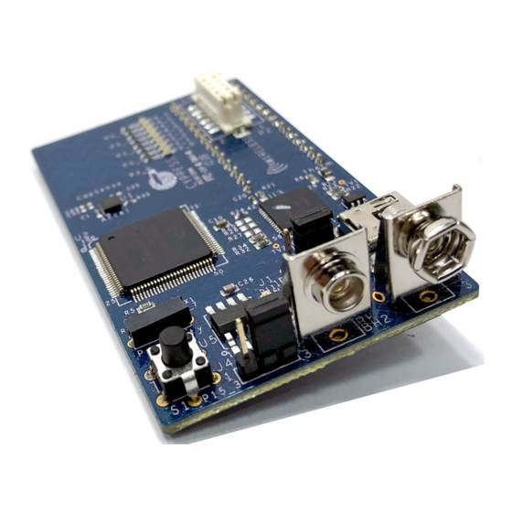
FX2LP High Speed USB The components indicated in Figure 2-1 are: 1. PSoC 3 100-pin TQFP (Cypress CY8C3866AXI-040 TQFP100) 2. Proximity Sensor Connector (Samtec Inc, BCS-101-L-S-HE) 3. Three Axis Accelerometer (Kionix, KXSC7-2050) 4. Five Segment CapSense Slider 5. Bank of Eight LEDs (Also Referred as LED Display in this user guide) 6. - Page 8 Note: Wireless modules such as ArtaFlex Radio Modules or Cypress Low power Radio modules such as CYWM6934/35 (not provided with the kit) can be plugged into the Wireless expansion con- nector on board. You may design your own radio module using the Cypress' CyFI-Low power chip CYRF7936-40LXI.
-
Page 9: Installation
Installation Install Hardware This section shows you how to use the PSoC 3 FirstTouch Starter Kit. Note: This kit comes with a factory programmed demonstration to display "PSoC Rocks!" message on the LED display when the board is waved. 1. Unpack the PSoC 3 FirstTouch Starter Kit. 2. -
Page 10: Install Software
After following these steps, you must have the following software installed: a. PSoC Creator 1.0 SP1 or later b. PSoC Programmer 3.12.4 or later c. Keil C51 Compiler (Cypress edition) CY8CKIT-003 PSoC 3 FirstTouch Starter Kit Guide, Spec. # 001-49613 Rev. *D... -
Page 11: Verify Kit Version
CY8C3866AXI-040, then congratulations, you own the latest version and This kit is equipped with production PSoC 3 silicon. To upgrade CY8CKIT-003 to CY8CKIT-003A, you can purchase our latest kits at www.cypress.com/ go/CY8CKIT-003. CY8CKIT-003 PSoC 3 FirstTouch Starter Kit Guide, Spec. # 001-49613 Rev. *D... - Page 12 Installation CY8CKIT-003 PSoC 3 FirstTouch Starter Kit Guide, Spec. # 001-49613 Rev. *D...
-
Page 13: Example Projects
1. From the Workspace Explorer, open the main.c file as shown in Figure 4-2. 2. Replace the "PSoC Rocks!" string in the DisplayString[ ] [ ] array of strings with "Cypress" or any other message(s) desired up to 25 characters. By default, it displays the following messages one by one: PSoC Rocks! ❐... -
Page 14: Build, Program, And Run The Psoc Rocks Project
Example Projects Figure 4-2. main.c File View 3. The number of times each string in the array is displayed can be adjusted by modifying the respective entry in the StringCycles[ ] array. Valid entries are 1-255. 4.1.3 Build, Program, and Run the PSoC Rocks Project 1. -
Page 15: Schematic Design Psoc Creator
Example Projects Figure 4-5. Program Successful 5. When the download is complete, remove the USB cable from the PSoC 3 FirstTouch Starter Kit board and connect a 9V battery to the battery connector. 6. Follow the steps in section 3.1 Install Hardware on page 9 to see your message displayed. -
Page 16: How The Psoc Rocks Project Works
Example Projects Figure 4-6. PSoC Rocks Schematic 4.1.5 How the PSoC Rocks Project Works This example displays a message using a bank of LEDs, that when swung in a back and forth arcing motion, produces a rasterized character display. The PSoC 3 FirstTouch Starter Kit has a three axis accelerometer. - Page 17 Example Projects Figure 4-7. PSoC Rocks Project Flowchart Boot Start Get ADC count (V) for measured accelerometer Y axis voltage V > minimum oscillation thershold? Calculate character offset in the string Update LED display String Complete Increment the Message Number Is Message Number >...
-
Page 18: Pcb Schematic
Example Projects 4.1.6 PCB Schematic Figure 4-8. PSoC Rocks Project PCB Schematic 3.3V 68 ohm 68 ohm P2_0 0603 0603 LED RED LED RED 68 ohm 68 ohm P2_1 0603 0603 LED RED LED RED 68 ohm 68 ohm P2_2 0603 0603 LED RED... -
Page 19: Bubble Level Emulator
Example Projects Bubble Level Emulator This project emulates a glass bubble level instrument using the onboard accelerometer and the LED display. When the program is run, the LEDs shows the direction in which the board is tilted. Running the Bubble Level Emulator project: 1. -
Page 20: How The Bubble Level Emulator Project Works
Example Projects 4.2.1 How the Bubble Level Emulator Project Works A bubble level displays the amount the level deviates from horizontal using a bubble of air in a glass via level. In this project, a level is emulated by the accelerometer on the board. In the case of the bubble level detection, LEDs display the tilt of the board along its length (corresponding to the X axis of the accelerometer). -
Page 21: Pcb Schematic
Example Projects 4.2.2 PCB Schematic Figure 4-11. Bubble Level Emulator Project PCB Schematic 3.3V 68 ohm 68 ohm P2_0 0603 0603 LED RED LED RED 68 ohm 68 ohm P2_1 0603 0603 LED RED LED RED 68 ohm 68 ohm P2_2 0603 0603... -
Page 22: Thermistortemperaturesense
Example Projects ThermistorTemperatureSense This project measures the current room temperature and displays it as a rasterized image when the board is waved. Running the ThermistorTemperatureSense project: 1. Connect the PSoC 3 FirstTouch Starter Kit board to the USB port of the PC through the USB cable. -
Page 23: Temperature Sensing Design Principle
Example Projects Figure 4-12. Temperature Sensor Project Flowchart Boot Update the raster display data array Start Read and process accelerometer Y axis voltage Calculate character offset If switch is pressed? in the string and update LED display Change temperature display mode String complete? Compute temperature 4.3.1.1... -
Page 24: Pcb Schematic
Example Projects Temperature is calculated by referring to a table of 165 known points on the resistance/temperature curve using a look up table. The table holds resistance values of the thermistor from -40 C to 125 C, in 1 C increments. Linear interpolation is used between the points in the table for temperature calculation up to two decimal places. -
Page 25: Capsense Slider
Example Projects CapSense Slider This project shows how to detect the position of a finger on the CapSense slider of the PSoC 3 First- Touch Starter Kit board and indicate its position on the LED display. Running the CapSense project: 1. - Page 26 Example Projects Figure 4-15. CapSense Slider Project Flowchart Boot Start Scan CapSense Slider Read the Centroid position is finger detected on the slider? Update LED display with respect to finger position CY8CKIT-003 PSoC 3 FirstTouch Starter Kit Guide, Spec. # 001-49613 Rev. *D...
-
Page 27: Pcb Schematic
Example Projects 4.4.2 PCB Schematic Figure 4-16. PCB Schematic for CapSense Slider Project 3.3V 68 ohm 68 ohm P2_0 0603 0603 LED RED LED RED 68 ohm 68 ohm P2_1 0603 0603 LED RED LED RED 68 ohm 68 ohm P2_2 0603 0603... -
Page 28: Proximity Sensor
Example Projects Proximity Sensor This project senses the presence of a finger near the proximity detection antenna. The number of LEDs that light up on the LED display on the PSoC 3 FirstTouch Starter Kit board increases as the finger gets closer to the antenna. To run the proximity sensor project, follow these steps: 1. -
Page 29: How The Proximity Sensor Project Works
Example Projects 4.5.1 How the Proximity Sensor Project Works Proximity detection is performed by a proximity antenna acting as a capacitive sensor. The proximity antenna consists of a wire connected to the proximity connector on the board. Upon power up, the board establishes a baseline capacitance value of the board along with the antenna attached to it. -
Page 30: Pcb Schematic
Example Projects 4.5.2 PCB Schematic Figure 4-19. PCB Schematic for Proximity Detection Project 3.3V 68 ohm 68 ohm P2_0 0603 0603 LED RED LED RED 68 ohm 68 ohm P2_1 0603 0603 LED RED LED RED 68 ohm 68 ohm P2_2 0603 0603... -
Page 31: Technical Reference
Technical Reference When creating a new project or modifying an existing project, refer to the PSoC 3 FirstTouch Starter Kit board schematic provided in section 5.1 PSoC 3 FirstTouch Starter Kit Schematic on page 32 the pin assignment tables listed in section 5.2 PSoC 3 Pin Assignment on PSoC 3 FirstTouch Starter Kit Board on page CY8CKIT-003 PSoC 3 FirstTouch Starter Kit Guide, Spec. -
Page 32: Psoc 3 Firsttouch Starter Kit Schematic
Technical Reference PSoC 3 FirstTouch Starter Kit Schematic Figure 5-1. PSoC 3 FirstTouch Starter Kit Design Schematic 0603 0603 CY8CKIT-003 PSoC 3 FirstTouch Starter Kit Guide, Spec. # 001-49613 Rev. *D... -
Page 33: Hardware Jumpers
Technical Reference 5.1.1 Hardware Jumpers There are two jumpers on the PCB for setting the power configuration. They are J1 and J4. These jumpers are for selecting the source for powering the PSoC 3. The options are to power the PSoC 3 from the on board 3.3V regulator, to run the PSoC 3 from the USB connector, or to supply power from off board using the J2/J3 connectors. -
Page 34: Board Layout
Technical Reference 5.1.2 Board Layout Figure 5-2. PDCR-9493 Rev ** Primary Side (Primary Silkscreen) CY8CKIT-003 PSoC 3 FirstTouch Starter Kit Guide, Spec. # 001-49613 Rev. *D... - Page 35 Technical Reference Figure 5-3. PDCR-9493 Rev ** Secondary Side (Secondary Silkscreen) CY8CKIT-003 PSoC 3 FirstTouch Starter Kit Guide, Spec. # 001-49613 Rev. *D...
-
Page 36: Bill Of Material (Bom)
5.1.3 Bill of Material (BOM) Table 5-1. Bill of Material (BOM) Item Qty Reference Description Manufacturer Mfr Part Number Cypress PDCR-9493 BATTERY HOLDER Keystone Electronics 594 9V Female PC MT BATTERY HOLDER Keystone Electronics 593 9V Male PC MT C1, C4, C6, C8, C9, C12, C13, C14, C15, CAP .1UF 16V... - Page 37 ERJ-2RKF1501X 16W 1% 0402 SMD LT SWITCH 6MM Panasonic - ECG EVQ-PBC07K 100GF H=7MM TH Tri-axis 1.5g-6, Analog KIONIX KXSC7-2050 3x3x0.9mm LGA PSoC 3 Programmable Cypress CY8C3866AXI-040 System-on-Chip Semiconductor IC, FX2 HIGH-SPEED USB PERIPHERAL Cypress CY7C68013A-56LTXC CONTROLLER Semiconductor QFN56 IC SERIAL EEPROM Microchip 128 BIT 2.5V SOT-23-...
- Page 38 Technical Reference Table 5-1. Bill of Material (BOM) (continued) Item Qty Reference Description Manufacturer Mfr Part Number NO LOAD Components C25, C29, C30 CAP 0402 NO LOAD RES 100K OHM 1/ R25, R26, R27 Yageo RC0603FR-07100KL 10W 1% 0603 SMD RES NO LOAD 0603 TEST VIA 40 HOLE 20 TV1, TV2...
- Page 39 Technical Reference PSoC 3 Pin Assignment on PSoC 3 FirstTouch Starter Kit Board Table 5-2. Pin Assignments Pin Number Port Number Design Function P2[5] Unused / No connect P2[6] General expansion connector J2 pin 13 P2[7] General expansion connector J3 pin 13 P12[4] Unused/No Connect P12[5]...
- Page 40 Technical Reference Table 5-2. Pin Assignments (continued) Pin Number Port Number Design Function No Connect No Connect P15[0] Accelerometer ST/Mode P15[1] Accelerometer Mode P3[0] CapSense slider element 1 P3[1] CapSense slider element 2 P3[2] CapSense slider element 3 P3[3] CapSense slider element 4 P3[4] CapSense slider element 5 P3[5]...
- Page 41 Technical Reference Table 5-2. Pin Assignments (continued) Pin Number Port Number Design Function P4[2] LED 7 drive P4[3] LED 8 drive P4[4] General expansion connector (J2) Pin 6 P4[5] General expansion connector (J3) Pin 6 P4[6] General expansion connector (J2) Pin 7 P4[7] General expansion connector (J3) Pin 7 Vccd...
- Page 42 Technical Reference CY8CKIT-003 PSoC 3 FirstTouch Starter Kit Guide, Spec. # 001-49613 Rev. *D...
- Page 43 Mouser Electronics Related Product Links 727-CY8CKIT-003A - Cypress Semiconductor CY8CKIT-003A...
Need help?
Do you have a question about the PSoC 3 FirstTouch CY8CKIT-003 and is the answer not in the manual?
Questions and answers