
Related Manuals for Cypress CY8CKIT-046


Summary of Contents for Cypress CY8CKIT-046
- Page 1 CY8CKIT-046 ® PSoC 4 L-Series Pioneer Kit Guide Doc. #: 002-03344 Rev. *D Cypress Semiconductor 198 Champion Court San Jose, CA 95134-1709 www.cypress.com...
- Page 2 Cypress is not liable, in whole or in part, and you shall and hereby do release Cypress from any claim, damage, or other liability arising from or related to all Unintended Uses of Cypress products.
-
Page 3: Table Of Contents
4.1.2 Using UART for Data Monitoring..............30 DeepSleep Blinky ......................31 4.2.1 Project Description ..................31 4.2.2 Hardware Connections...................31 4.2.3 Verify Output ....................31 CapSense Proximity ....................33 4.3.1 Project Description ..................33 4.3.2 Hardware Connections...................33 CY8CKIT-046 PSoC® 4 L-Series Pioneer Kit Guide, Doc. #: 002-03344 Rev. *D... - Page 4 A.3.3 Write/Read Operation ..................76 Migrating Projects across different Pioneer Series Kits ..........78 A.4.1 Arduino-Compatible Headers.................79 A.4.2 Onboard Peripherals ..................83 KitProg Status LED States..................85 Bill of Materials ......................86 Revision History CY8CKIT-046 PSoC® 4 L-Series Pioneer Kit Guide, Doc. #: 002-03344 Rev. *D...
-
Page 5: Safety Information
This kit has an end-of life five years from the date of manufacture mentioned on the back of the box. Contact your nearest recycler for discarding the kit. CY8CKIT-046 PSoC® 4 L-Series Pioneer Kit Guide, Doc. #: 002-03344 Rev. *D... - Page 6 Use a conductive foam pad if available. Do not slide the board over any surface. CY8CKIT-046 PSoC® 4 L-Series Pioneer Kit Guide, Doc. #: 002-03344 Rev. *D...
-
Page 7: Introduction
Functional Description on page 58 for details. You will use PSoC Creator™ to develop and debug your PSoC 4200L projects. PSoC Creator is Cypress’ standard integrated design environment (IDE). If you are new to PSoC Creator, see the documentation on the PSoC Creator home page. -
Page 8: Board Details
Board Details The PSoC 4 L-Series Pioneer Kit consists of the following blocks, as shown in Figure 1-2. Figure 1-3 shows the complete kit headers pin mapping. CY8CKIT-046 PSoC® 4 L-Series Pioneer Kit Guide, Doc. #: 002-03344 Rev. *D... - Page 9 Introduction Figure 1-2. PSoC 4 L-Series Pioneer Kit Markup PSoC 4 L-Series Pioneer Board Details 11 12 13 14 15 16 ® ® CY8CKIT-046 PSoC® 4 L-Series Pioneer Kit Guide, Doc. #: 002-03344 Rev. *D...
- Page 10 P7_3 P11_1/D1 P7_2 P11_0/D11 P0_0 P1_4/A0 Arduino Uno R3 P0_1 P1_5/A1 P4_4 P1_6/A2 PSoC 4 L-Series Pioneer Kit P4_5 P1_7/A3 Digilent Pmod P4_6 P2_6/A4 P4_7 P2_7/A5 Character LCD CY8CKIT-046 PSoC® 4 L-Series Pioneer Kit Guide, Doc. #: 002-03344 Rev. *D...
-
Page 11: Psoc Creator
Filter for examples based on device family or keyword. ■ Select from the list of examples offered based on the Filter Options. ■ View the documentation for the selection (on the Documentation tab). ■ CY8CKIT-046 PSoC® 4 L-Series Pioneer Kit Guide, Doc. #: 002-03344 Rev. *D... -
Page 12: Kit Code Examples
Kits under Start; then, expand the specific kit to see the code examples. Refer to the section Using the Kit Code Examples on page 27 for a detailed explanation on how to access the kit code examples. CY8CKIT-046 PSoC® 4 L-Series Pioneer Kit Guide, Doc. #: 002-03344 Rev. *D... -
Page 13: Psoc Creator Help
PSoC 4 Component datasheets. Getting Started This guide will help you get acquainted with the CY8CKIT-046 PSoC 4 L-Series Pioneer Kit: Software Installation chapter on page 17 describes the installation of the kit software. This ■... -
Page 14: Technical Support
Click the File icon and then click Open. Times New Roman Displays an equation: 2 + 2 = 4 Text in gray boxes Describes Cautions or unique functionality of the product. CY8CKIT-046 PSoC® 4 L-Series Pioneer Kit Guide, Doc. #: 002-03344 Rev. *D... -
Page 15: Acronyms
PRoC Programmable Radio-on-Chip PSoC Programmable Systems-on-Chip pulse width modulator red green blue successive approximation register serial peripheral interface serial wire debug TRRS Tip-Ring-Ring-Sleeve UART universal asynchronous receiver transmitter CY8CKIT-046 PSoC® 4 L-Series Pioneer Kit Guide, Doc. #: 002-03344 Rev. *D... - Page 16 Introduction Table 1-2. Acronyms Used in the Document Acronym Description universal serial bus USB-IF USB Implementers Forum watch crystal oscillator watchdog timer CY8CKIT-046 PSoC® 4 L-Series Pioneer Kit Guide, Doc. #: 002-03344 Rev. *D...
-
Page 17: Software Installation
(listed in step 5) are installed on your computer. c. CY8CKIT-046 DVD ISO: This file is a complete package, stored in a DVD-ROM image format, which you can use to create a DVD or extract using an ISO extraction program such as ®... - Page 18 Software Installation 3. Click Install CY8CKIT-046 to start the kit installation, as shown in Figure 2-1. Figure 2-1. Kit Installer Screen 4. Select the directory in which you want to install the files related to the PSoC 4 L-Series Pioneer Kit.
-
Page 19: Uninstall Software
Uninstall Software The software can be uninstalled using one of the following methods: 1. Go to Start > All Programs > Cypress > Cypress Update Manager and select the Uninstall button next to the product that needs to be uninstalled. -
Page 20: Kit Operation
High Speed I/O Matrix Active/Sleep Deep Sleep Hibernate 80x GPIO, 14x GPIO_OVT, 2x SIO I/O Subsystem Figure 3-2 shows the block diagram for the PSoC 4 L-Series Pioneer Kit. CY8CKIT-046 PSoC® 4 L-Series Pioneer Kit Guide, Doc. #: 002-03344 Rev. *D... - Page 21 4200L device. This clock sources peripherals such as real-time clock (RTC) and watchdog timer (WDT), which operate in the device’s low-power modes. CY8CKIT-046 PSoC® 4 L-Series Pioneer Kit Guide, Doc. #: 002-03344 Rev. *D...
- Page 22 PSoC 4200L device to Pmod peripheral modules through I2C and SPI interfaces. 9. Cypress F-RAM (FM24V10-G, U6): This kit features a Cypress F-RAM device of 1 Mb capacity. The F-RAM is connected to the I2C interface of the PSoC 4200L device. The F-RAM device can be used similar to an external EEPROM memory for data logging operations.
- Page 23 3.5-mm audio jack to interface standard Tip-Ring-Ring-Sleeve (TRRS) headsets with a microphone. 18. Cypress Energy Harvesting PMIC (footprint only, U12): The kit includes a footprint (U12) for S6AE101A, an Energy Harvesting PMIC from Cypress. The PMIC provides power to the EZ-BLE PRoC Module, U8.
-
Page 24: Kitprog
The target PSoC 4200L device can be programmed and debugged using the built-in KitProg. Before programming the device, ensure that PSoC Creator and PSoC Programmer are installed on your computer. See Install Software on page 17 for more information. CY8CKIT-046 PSoC® 4 L-Series Pioneer Kit Guide, Doc. #: 002-03344 Rev. *D... -
Page 25: Programming Using Psoc Creator
Program or press [Ctrl] [F5], as shown in Figure 3-6. This programs the target PSoC 4200L device on the PSoC 4 L-Series Pioneer Kit; the kit is now ready for use. CY8CKIT-046 PSoC® 4 L-Series Pioneer Kit Guide, Doc. #: 002-03344 Rev. *D... -
Page 26: Debugging Using Psoc Creator
The KitProg firmware normally does not require any update. You can use PSoC Programmer to update the KitProg firmware. Refer to section 3.5 of the for more details. KitProg User Guide CY8CKIT-046 PSoC® 4 L-Series Pioneer Kit Guide, Doc. #: 002-03344 Rev. *D... -
Page 27: Code Examples
Follow these steps to open and use the code examples provided with the kit. 1. Launch PSoC Creator from Start > All Programs > Cypress > PSoC Creator<version> > PSoC Creator <version>. 2. On the Start Page, expand CY8CKIT-046 under Start > Kits. The code examples shipped with the kit appear (see Figure 4-1). - Page 28 If this is the first time the kit is connected, wait for the drivers to be installed. 6. Choose Debug > Program in PSoC Creator as shown in Figure 4-3. Figure 4-3. Program Device in PSoC Creator CY8CKIT-046 PSoC® 4 L-Series Pioneer Kit Guide, Doc. #: 002-03344 Rev. *D...
- Page 29 Figure 4-5. Connect Device From PSoC Creator and Program 9. After programming is successful, the green LED (LED3) on the board will toggle at a rate of approximately 1 Hz. CY8CKIT-046 PSoC® 4 L-Series Pioneer Kit Guide, Doc. #: 002-03344 Rev. *D...
-
Page 30: Using Capsense Tuner
PSoC 4200L, which in turn is connected to the KitProg's USB-UART bridge. The UART output is enabled by default in both the USB Audio and USB Mouse examples. Figure 4-7. UART Settings (Tera Term) CY8CKIT-046 PSoC® 4 L-Series Pioneer Kit Guide, Doc. #: 002-03344 Rev. *D... -
Page 31: Deepsleep Blinky
PSoC 4200L (J14). 5. Connect an ammeter across the terminals 3 and 4 of the power measurement header, as shown Figure 4-9. CY8CKIT-046 PSoC® 4 L-Series Pioneer Kit Guide, Doc. #: 002-03344 Rev. *D... - Page 32 SWD. Figure 4-10. Enabling Debug in a Code Example Note: More details on the power measurement header terminals is provided in A.2.1.3 Power System on page CY8CKIT-046 PSoC® 4 L-Series Pioneer Kit Guide, Doc. #: 002-03344 Rev. *D...
-
Page 33: Capsense Proximity
1. Connect the PSoC 4 L-Series Pioneer Kit to the PC through USB connector J10. 2. Program the PSoC 4 L-Series Pioneer Kit with the CY8CKIT_046_CapSense_Proximity code example. CY8CKIT-046 PSoC® 4 L-Series Pioneer Kit Guide, Doc. #: 002-03344 Rev. *D... -
Page 34: Proximity Gestures
– Wave UP gesture and Wave DOWN gesture. Figure 4-13 Figure 4-14 show the Wave UP and Wave DOWN gestures, respectively. The color of the RGB LED changes CY8CKIT-046 PSoC® 4 L-Series Pioneer Kit Guide, Doc. #: 002-03344 Rev. *D... - Page 35 Wave UP Red > Green > Blue > Red Wave DOWN Red > Blue > Green > Red a. Each Wave UP/DOWN gesture will trigger an LED color transition. CY8CKIT-046 PSoC® 4 L-Series Pioneer Kit Guide, Doc. #: 002-03344 Rev. *D...
-
Page 36: Hardware Connections
The LED brightness level is controlled by the buttons and the proximity signal provides a mul- tiplication factor to the brightness output from the buttons. Figure 4-16 shows the CapSense Gesture CY8CKIT-046 PSoC® 4 L-Series Pioneer Kit Guide, Doc. #: 002-03344 Rev. *D... -
Page 37: Hardware Connections
Figure 4-11 on page 4.5.3 Verify Output To verify the CapSense Proximity code example, follow these steps: 1. Power the PSoC 4 L-Series Pioneer Kit through USB connector J10. CY8CKIT-046 PSoC® 4 L-Series Pioneer Kit Guide, Doc. #: 002-03344 Rev. *D... -
Page 38: Usb Mouse
This code example demonstrates a simple USB human interface device (HID) implementation (mouse/keyboard) using the CapSense Gesture Pad present in the CY8CKIT-046 PSoC 4 L-Series Pioneer Kit. In addition to emulating mouse/keyboard over USB, the example also controls the RGB LED intensity. - Page 39 Action (Mouse/Keyboard) Action (RGB LED) Mouse left-click None Left button tap Right button tap Mouse right-click None Turn ON/OFF RGB Mouse center-click Middle button tap CTRL+TAB None Right swipe CY8CKIT-046 PSoC® 4 L-Series Pioneer Kit Guide, Doc. #: 002-03344 Rev. *D...
- Page 40 Down swipe and Scroll down None hold Change RGB LED color: Violet > Indigo None > Blue > Green > Inner clockwise Yellow > Orange > Red > Violet CY8CKIT-046 PSoC® 4 L-Series Pioneer Kit Guide, Doc. #: 002-03344 Rev. *D...
- Page 41 Inner circular gestures and outer circular gestures are mutually exclusive; moving to the outer circle from the inner circle or vice-versa will NOT report any gestures until the finger is removed from the Gesture Pad and the gestures are tried again. CY8CKIT-046 PSoC® 4 L-Series Pioneer Kit Guide, Doc. #: 002-03344 Rev. *D...
-
Page 42: Hardware Connections
4-17. USB drivers should install automatically and the kit should enumerate as a USB Composite device as shown in Figure 4-18. Figure 4-18. PSoC 4200L USB HID Enumeration CY8CKIT-046 PSoC® 4 L-Series Pioneer Kit Guide, Doc. #: 002-03344 Rev. *D... -
Page 43: Usb Audio
(syn- chronous, asynchronous, or adaptive). The example implements an asynchronous audio device at a CY8CKIT-046 PSoC® 4 L-Series Pioneer Kit Guide, Doc. #: 002-03344 Rev. *D... - Page 44 Pad are different from the ones supported over the audio control endpoint described earlier along with the audio streaming endpoints. The gestures supported in this example and the respective media control settings are listed in Table 4-4. CY8CKIT-046 PSoC® 4 L-Series Pioneer Kit Guide, Doc. #: 002-03344 Rev. *D...
- Page 45 Table 4-4. CapSense Gestures and Media Control Actions Gesture Gesture Activation Media Control Left button tap Previous track Right button tap Next track Middle button tap Play/Pause Up button tap Speaker mute CY8CKIT-046 PSoC® 4 L-Series Pioneer Kit Guide, Doc. #: 002-03344 Rev. *D...
- Page 46 Code Examples Table 4-4. CapSense Gestures and Media Control Actions Gesture Gesture Activation Media Control Down button tap Stop Right swipe Next track Left swipe Previous track CY8CKIT-046 PSoC® 4 L-Series Pioneer Kit Guide, Doc. #: 002-03344 Rev. *D...
-
Page 47: Hardware Connections
Optionally, the headphone can have a mono microphone output. The kit ships with a stereo audio earphone with microphone, which can be used to test the example. To test the example, perform the following hardware connections and settings. CY8CKIT-046 PSoC® 4 L-Series Pioneer Kit Guide, Doc. #: 002-03344 Rev. *D... - Page 48 AHJ position; if you do not hear a continuous clicking or static noise, then the headset is AHJ type. Set to OMTP position otherwise. Figure 4-19. USB Audio Example Hardware Setup CY8CKIT-046 PSoC® 4 L-Series Pioneer Kit Guide, Doc. #: 002-03344 Rev. *D...
-
Page 49: Verify Output
Figure 4-21. PSoC 4200L USB Audio Enumeration 5. After successful driver installation, for stereo audio playback, go to Start > Control Panel > Sound and set Speakers (CY8CKIT-046 USB Audio) as default device under Playback tab, as shown in Figure 4-22. - Page 50 Code Examples Figure 4-22. Selecting CY8CKIT-046 USB Audio as Default Playback Device Figure 4-23. Selecting CY8CKIT-046 USB Audio as Default Recording Device CY8CKIT-046 PSoC® 4 L-Series Pioneer Kit Guide, Doc. #: 002-03344 Rev. *D...
- Page 51 Playback and Recording tab in Sound settings. Hence, when you update the sample rate in any tab of the CY8CKIT-046 USB Audio device, you need to manually update the same sample rate in the other tab as well for proper glitch-free streaming of audio between the kit and the PC.
-
Page 52: Appendix
Document Number FAB DRW: 610-60265-01 630-60271-01 630-60271-01 630-60271-01 ASSY DRW: 620-60273-01 Date: Date: Date: Monday, October 12, 2015 Monday, October 12, 2015 Monday, October 12, 2015 Sheet Sheet Sheet CY8CKIT-046 PSoC® 4 L-Series Pioneer Kit Guide, Doc. #: 002-03344 Rev. *D... - Page 53 Document Number FAB DRW: 610-60265-01 630-60271-01 630-60271-01 630-60271-01 ASSY DRW: 620-60273-01 Date: Date: Date: Monday, October 12, 2015 Monday, October 12, 2015 Monday, October 12, 2015 Sheet Sheet Sheet CY8CKIT-046 PSoC® 4 L-Series Pioneer Kit Guide, Doc. #: 002-03344 Rev. *D...
- Page 54 Place each pair of caps close to Power Pins FAB DRW: 610-60265-01 630-60271-01 630-60271-01 630-60271-01 ASSY DRW: 620-60273-01 Date: Date: Date: Monday, October 12, 2015 Monday, October 12, 2015 Monday, October 12, 2015 Sheet Sheet Sheet CY8CKIT-046 PSoC® 4 L-Series Pioneer Kit Guide, Doc. #: 002-03344 Rev. *D...
- Page 55 Document Number FAB DRW: 610-60265-01 630-60271-01 630-60271-01 630-60271-01 ASSY DRW: 620-60273-01 Date: Date: Date: Monday, October 12, 2015 Monday, October 12, 2015 Monday, October 12, 2015 Sheet Sheet Sheet CY8CKIT-046 PSoC® 4 L-Series Pioneer Kit Guide, Doc. #: 002-03344 Rev. *D...
- Page 56 Size Document Number Document Number Document Number 630-60271-01 630-60271-01 630-60271-01 Date: Date: Date: Monday, October 12, 2015 Monday, October 12, 2015 Monday, October 12, 2015 Sheet Sheet Sheet CY8CKIT-046 PSoC® 4 L-Series Pioneer Kit Guide, Doc. #: 002-03344 Rev. *D...
- Page 57 Document Number FAB DRW: 610-60265-01 630-60271-01 630-60271-01 630-60271-01 ASSY DRW: 620-60273-01 Date: Date: Date: Monday, October 12, 2015 Monday, October 12, 2015 Monday, October 12, 2015 Sheet Sheet Sheet CY8CKIT-046 PSoC® 4 L-Series Pioneer Kit Guide, Doc. #: 002-03344 Rev. *D...
-
Page 58: Hardware Functional Description
USB-I2C and USB-UART bridge support to the onboard devices and peripherals. The PSoC 5LP device can also be reprogrammed to provide other user functions. The PSoC 5LP connects to the CY8CKIT-046 PSoC® 4 L-Series Pioneer Kit Guide, Doc. #: 002-03344 Rev. *D... - Page 59 NO LOAD NO LOAD GND Test Points Power Supply The input to the LDO can be from either the USB or the VIN pin in the Arduino header. CY8CKIT-046 PSoC® 4 L-Series Pioneer Kit Guide, Doc. #: 002-03344 Rev. *D...
- Page 60 3 & 4 -> Short out shunts, VDD to P4L_VDD TP15 ZERO No Shunt -> No power to U5, PSoC 4200L NO LOAD NO LOAD VTARG ZERO Power Monitoring CY8CKIT-046 PSoC® 4 L-Series Pioneer Kit Guide, Doc. #: 002-03344 Rev. *D...
- Page 61 F-RAM, codec, and I2C slaves. As a result, removing the power jumper can potentially back power PSoC 4200L through the device I/Os interfacing these pull-ups CY8CKIT-046 PSoC® 4 L-Series Pioneer Kit Guide, Doc. #: 002-03344 Rev. *D...
- Page 62 Kit. A resettable poly fuse is used to protect the computer's USB port from shorts and over current. If more than 500 mA is drawn from the USB Mini-B connector, the fuse will automatically break the connection until the short or overload is removed. CY8CKIT-046 PSoC® 4 L-Series Pioneer Kit Guide, Doc. #: 002-03344 Rev. *D...
- Page 63 4200L for custom PSoC 5LP applications. By default, the SPI connections are not enabled on the board. You need to populate R61, R53, R59, and R68 (shown in Figure A-7) to enable these connec- tions. CY8CKIT-046 PSoC® 4 L-Series Pioneer Kit Guide, Doc. #: 002-03344 Rev. *D...
- Page 64 P4[1] I2C data line P4[0] I2C clock line ADCDAT P3[7] Audio (ADC) digital data output (microphone) from codec DACDAT P3[6] Audio (DAC) digital data input (speakers) to codec CY8CKIT-046 PSoC® 4 L-Series Pioneer Kit Guide, Doc. #: 002-03344 Rev. *D...
- Page 65 CapSense shield signal is required. Populating R110 brings the CapSense shield con- nection to one of the Arduino headers when plugged into a baseboard. For the CY8CKIT-046 PSoC 4 L-Series Pioneer Kit, the shield signal will be connected to P0[3], when the snapped shield board is connected to CY8CKIT-046 Arduino headers.
- Page 66 The level translator on the shield board, U10, translates the SPI signals from PSoC 4200L to 3.3 V level to be used with µSD card or Serial NOR Flash interface. This is shown in Figure A-9. CY8CKIT-046 PSoC® 4 L-Series Pioneer Kit Guide, Doc. #: 002-03344 Rev. *D...
-
Page 67: Shield Board
The PSoC 4 L-Series Pioneer Kit has five additional Arduino-compatible headers on the shield board–J17, J18, J19, J20, and J24. Header J17 is marked 18 and headers J18, J19, and J20 are CY8CKIT-046 PSoC® 4 L-Series Pioneer Kit Guide, Doc. #: 002-03344 Rev. *D... - Page 68 BLE chip, two crystals, chip antenna, shield, and passive components. Refer to AN96841 - Getting for more details. Visit www.cypress.com/ez-bleprocmodule/ Started with EZ-BLE™ Creator Modules to buy the EZ-BLE PRoC Module. CY8CKIT-046 PSoC® 4 L-Series Pioneer Kit Guide, Doc. #: 002-03344 Rev. *D...
- Page 69 5-pin SWD header (marked 25 in Figure A-1 on page 58). The footprint for populating the CMOD capacitor (C90, 2.2 nF) required to develop CapSense applications with the EZ-BLE PRoC Module CY8CKIT-046 PSoC® 4 L-Series Pioneer Kit Guide, Doc. #: 002-03344 Rev. *D...
- Page 70 Note that to use the PMIC, the EZ-BLE PRoC Module should be populated, all the components shown in Figure A-12 should be populated, L4/L3 should be removed, and L5/L6 should be populated. CY8CKIT-046 PSoC® 4 L-Series Pioneer Kit Guide, Doc. #: 002-03344 Rev. *D...
-
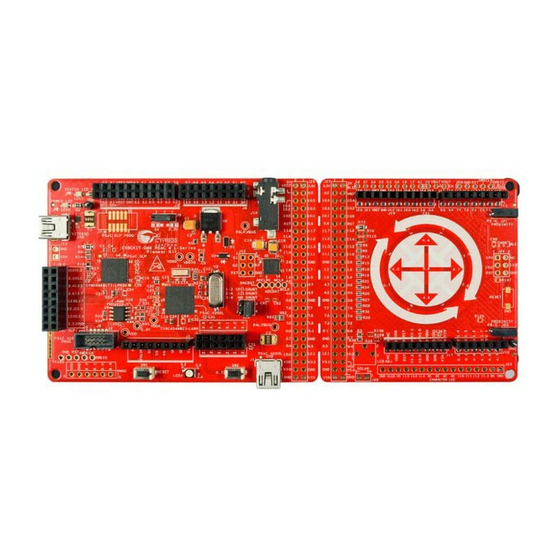
Page 71: Board Separation (Snapping)
After snapping out, the main board acts as an Arduino baseboard and the shield board can be used as an Arduino shield board. Figure A-13. CY8CKIT-046 Board Separation Main board Shield board CY8CKIT-046 PSoC® 4 L-Series Pioneer Kit Guide, Doc. #: 002-03344 Rev. *D... - Page 72 CY8CKIT-042 and CY8CKIT-044. This board can also be used as a shield with the CY8CKIT-046 main board. To use the board as a shield, the even pins on headers J17, J18, J19, and J20 should be populated with male headers that can plug into an Arduino baseboard.
- Page 73 Appendix Figure A-15. CY8CKIT-046 Shield Board as Arduino Shield (with CY8CKIT-046 Main Board) Arduino Shield headers Figure A-16. CY8CKIT-046 Shield Board as Arduino Shield (with CY8CKIT-044) The shield pins that connect to the baseboard are also connected to CapSense Gesture Pad ele- ments (13 sensors), CapSense proximity sensors (two sensors), CapSense shield signal, SPI lines (µSD card or Serial NOR Flash interface), and I2C lines (EZ-BLE PRoC Module interface) on the...
- Page 74 Note that this connection will bypass the onboard protection diodes, and any external voltage larger than 3.3 V and 5 V on the respective domains will damage the active components connected on this domain. CY8CKIT-046 PSoC® 4 L-Series Pioneer Kit Guide, Doc. #: 002-03344 Rev. *D...
-
Page 75: Using Fm24V10 F-Ram
Note: The 8-pin SOIC footprint provided for the F-RAM FM24V10 on the PSoC 4 L-Series Pioneer Kit is compatible with all I2C-based F-RAM devices from Cypress (FM24Vxx, FM24CLxx, and CY15BxxxJ parts). The F-RAM parts with more than 64 KB size support only four addresses (four devices of the same type on the same I2C bus);... -
Page 76: High Speed Mode (Hs-Mode)
The F-RAM device datasheet includes details on how to perform a write/read operation with F-RAM. Figure A-21 Figure A-22 show the write/read packet structure as a quick reference. Figure A-21. F-RAM Write Packet Structure Single-Byte Write CY8CKIT-046 PSoC® 4 L-Series Pioneer Kit Guide, Doc. #: 002-03344 Rev. *D... - Page 77 Note: Visit the CY15FRAMKIT-001 kit webpage for code examples and the Arduino library for inter- facing I2C F-RAM devices with the PSoC 4 family. CY8CKIT-046 PSoC® 4 L-Series Pioneer Kit Guide, Doc. #: 002-03344 Rev. *D...
-
Page 78: Migrating Projects Across Different Pioneer Series Kits
Pioneer series kits. The CY8CKIT-046 PSoC 4 L-Series Pioneer Kit has an additional shield board, which offers another set of Arduino-compatible pins. The pins present in the side board are completely independent of the ones present in the main board and hence offer the ability to use two Arduino shields simultaneously. -
Page 79: Arduino-Compatible Headers
– – – – P1[1] P3[5] a. These pins are also used for onboard peripheral connections. Refer to the “Onboard Peripherals” on page 83 section for connection details. CY8CKIT-046 PSoC® 4 L-Series Pioneer Kit Guide, Doc. #: 002-03344 Rev. *D... - Page 80 P1[5] P3[1] P3[1] P8[1] P0[7] P1[6] P1[0] P1[0] P0[7] P8[2] P3[7] P1[7] P1[1] P1[1] P3[2] P8[3] P0[0] P0[3] P1[3] P1[2] P1[2] P8[4] P3[5] P3[0] P1[2] P1[3] P1[3] P8[5] CY8CKIT-046 PSoC® 4 L-Series Pioneer Kit Guide, Doc. #: 002-03344 Rev. *D...
- Page 81 IOREF IOREF Table A-8. J18 Arduino-Compatible Header Pin Map Pioneer Series Kit Arduino CY8CKIT-046 Shield Board P1[4] – P0[0]/CS_RS_E4 P1[5] – P0[1]/CS_RS_E5 P1[6] – P4[4]/CS_GES_UP P1[7] – P4[5]/CS_GES_LT CY8CKIT-046 PSoC® 4 L-Series Pioneer Kit Guide, Doc. #: 002-03344 Rev. *D...
- Page 82 P10[2] P10[2] AREF VREF VREF P12[1] P12[1] P12[0] P12[0] Table A-10. J20 Arduino-Compatible Header Pin Map Pioneer Series Kit Arduino CY8CKIT-046 Shield Board P11[0]/LCD_D4 P7[2]/CS_RS_E6 P11[1]/LCD_D5 P7[3]/CS_RS_E7 P11[2]/LCD_D6 CY8CKIT-046 PSoC® 4 L-Series Pioneer Kit Guide, Doc. #: 002-03344 Rev. *D...
-
Page 83: Onboard Peripherals
CS_RS_E3 CapSense P0[0]/ – – – – Sensor 6 CS_RS_E4 CapSense P0[1]/ – – – – Sensor 7 CS_RS_E5 CapSense P7[2]/ – – – – Sensor 8 CS_RS_E6 CY8CKIT-046 PSoC® 4 L-Series Pioneer Kit Guide, Doc. #: 002-03344 Rev. *D... - Page 84 Shield a. The CapSense elements are present on the CY8CKIT-046 shield board. The radial slider (CapSense sensors 6 to 13) is symmetric and the sensor order can be shifted to fit your requirement, that is, the desired zero position on the slider.
-
Page 85: Kitprog Status Led States
This may happen if the kit is not powered LED is OFF Power LED is ON from the USB host. Verify the USB cable and check if PSoC Programmer is installed on the PC. CY8CKIT-046 PSoC® 4 L-Series Pioneer Kit Guide, Doc. #: 002-03344 Rev. *D... -
Page 86: Bill Of Materials
CONN HEADER .100 DUAL STR Protectron Elec- 2X2 RECP P9103-04-12-1 4POS tromech JACK-EAR- 3.5mm SMD EARPHONE JACK,(TSH- SJ-43516-SMT PHONE-ACI 3756) CONN RCPT 1POS .100" SNGL J21,J22 Prox CON Samtec Inc BCS-101-L-S-HE HORZ CY8CKIT-046 PSoC® 4 L-Series Pioneer Kit Guide, Doc. #: 002-03344 Rev. *D... - Page 87 TEST POINT PC MINI .040"D Black 5001 tronics PUSBM12VX NXP Semicon- U1,U7 TVS DIODE 5.5VWM 12VC 6HXSON PUSBM12VX4-TL,115 4-TL,115 ductors NCP1117DTA ON Semiconduc- IC REG LDO ADJ 1A DPAK NCP1117DTARKG CY8CKIT-046 PSoC® 4 L-Series Pioneer Kit Guide, Doc. #: 002-03344 Rev. *D...
- Page 88 Solutions Protectron Elec- J12,J24 3x2 RECPT CONN HEADER MALE 6PS .1" GOLD P9403-06-21 tromech CONN HEADER MALE 2POS .1" Protectron Elec- J13,J28 2 PIN HDR P9401-02-21 GOLD tromech CY8CKIT-046 PSoC® 4 L-Series Pioneer Kit Guide, Doc. #: 002-03344 Rev. *D...
- Page 89 Stackpole Elec- 1 ohm RES SMD 1 OHM 1% 1/4W 1206 RMCF1206FT1R00 tronics Inc Stackpole Elec- 10 ohm RES SMD 10 OHM 1% 1/4W 1206 RMCF1206FT10R0 tronics Inc CY8CKIT-046 PSoC® 4 L-Series Pioneer Kit Guide, Doc. #: 002-03344 Rev. *D...
-
Page 90: Revision History
“Migrating Projects across different Pioneer Series Kits” on page Updated Figure A-23. Updated “Bill of Materials” on page Updated the and board images 05/11/2017 GNKK Updated the Cypress logo and copyright information. CY8CKIT-046 PSoC® 4 L-Series Pioneer Kit Guide, Doc. #: 002-03344 Rev. *D... - Page 91 Updated “Technical Support” on page Updated description. Updated Software Installation chapter on page Updated description. Updated “Install Software” on page Updated description. Updated Figure 2-1. Updated Figure 2-2. CY8CKIT-046 PSoC® 4 L-Series Pioneer Kit Guide, Doc. #: 002-03344 Rev. *D...
- Page 92 “Using the Kit Code Examples” on page Updated description. Updated Figure 4-1. Updated “Using CapSense Tuner” on page Updated description. Updated “CapSense Buttons” on page Updated “Project Description” on page Updated description. CY8CKIT-046 PSoC® 4 L-Series Pioneer Kit Guide, Doc. #: 002-03344 Rev. *D...
- Page 93 “Migrating Projects across different Pioneer Series Kits” on page Replaced “s” with “Projects” in heading. Updated description. Updated “Arduino-Compatible Headers” on page Updated Table A-7. Updated to new template. 6336955 MSUR Sunset review. CY8CKIT-046 PSoC® 4 L-Series Pioneer Kit Guide, Doc. #: 002-03344 Rev. *D...
Need help?
Do you have a question about the CY8CKIT-046 and is the answer not in the manual?
Questions and answers