Table of Contents
Advertisement
Quick Links
Getting Started with PSoC 6 MCU
To access an ever-growing list of hundreds of PSoC code examples, please visit our
web
page. You can also explore the PSoC video library here.
AN221774 introduces the PSoC 6 MCU, a dual-CPU programmable system-on-chip with Arm
®
Cortex
M4 and Cortex-M0+ processors. This application note helps you explore PSoC 6 MCU
-
architecture and development tools, and shows you how to create your first project using PSoC Creator.
This application note also guides you to more resources available online to accelerate your learning
about PSoC 6 MCU. To get started with the PSoC 6 MCU with BLE Connectivity device family, refer to
- Getting Started with PSoC 6 MCU with BLE Connectivity.
AN210781
Contents
1 Introduction .................................................................. 2
1.1 Prerequisites ....................................................... 3
2 Development Ecosystem ............................................. 3
2.1 PSoC Resources ................................................ 3
2.2 Firmware/Application Development .................... 4
2.3 Support for Other IDEs ....................................... 6
2.4 RTOS Support .................................................... 8
2.5 Debugging........................................................... 8
WiFi-BT Pioneer Kit ............................................ 8
3 Device Features .......................................................... 9
4 My First PSoC 6 MCU Design ................................... 10
4.1 Using These Instructions................................... 10
www.cypress.com
Associated Part Family: All
Associated Application Notes and Code Examples:
More code examples? We heard you.
Document No. 002-21774 Rev. **
Authors: Srinivas Nudurupati, Vaisakh K V
Software Version:
4.2 About the Design .............................................. 11
4.4 Part 2: Implement the Design ........................... 16
4.5 Part 3: Generate Source Code ......................... 24
4.6 Part 4: Write the Firmware ................................ 26
Program the Device .......................................... 30
4.8 Part 6: Test Your Design ................................... 32
5 Summary ................................................................... 33
6 Related Application Notes and Code Examples ........ 34
Glossary ................................................ 36
Device Features .................................... 37
Cypress IoT Development Tools ........... 43
AN221774
®
PSoC
6 MCU
devices
PSoC Creator™ 4.2
Click
here.
code examples
®
1
Advertisement
Table of Contents

Subscribe to Our Youtube Channel
Related Manuals for Cypress CY8CKIT-062-WiFi-BT


Summary of Contents for Cypress CY8CKIT-062-WiFi-BT
-
Page 1: Table Of Contents
3 Device Features ............9 Appendix A. Glossary ..........36 4 My First PSoC 6 MCU Design ........10 Appendix B. Device Features ........37 4.1 Using These Instructions........10 Appendix C. Cypress IoT Development Tools ... 43 www.cypress.com Document No. 002-21774 Rev. **... -
Page 2: Introduction
Getting Started with PSoC 6 MCU Introduction PSoC 6 MCU is Cypress‘ ultra-low-power PSoC device with a dual-CPU architecture tailored for smart homes, IoT gateways, etc. The Cypress PSoC 6 MCU device is a programmable embedded system-on-chip that integrates the following features on a single chip: ... -
Page 3: Prerequisites
1 . 1 . 1 H a r d w a r e CY8CKIT-062-WiFi-BT PSoC 6 WiFi-BT Pioneer Kit CY8CKIT-062-BLE PSoC 6 BLE Pioneer Kit 1 . 1 . 2 S o f t w a r e ... -
Page 4: Firmware/Application Development
Getting Started with PSoC 6 MCU Firmware/Application Development Cypress PSoC Creator and the Peripheral Driver Library (PDL) are at the heart of the development process. PSoC Creator brings together several digital/analog/system Components and firmware to build an application. Using PSoC Creator, you can select, place, and configure Components on a schematic; write C/assembly source code; and program and debug the device. - Page 5 PSoC Creator provides Components that are based on PDL for your use with PSoC 6 MCU devices. This retains the essence of PSoC Creator in utilizing Cypress or community-developed and pre-validated Components. However, the PDL is a source code library that you can use with any development environment.
-
Page 6: Support For Other Ides
U s i n g P S o C C r e a t o r t o T a r g e t A n o t h e r I D E Cypress recommends that you use PSoC Creator to set up and configure PSoC 6 MCU system resources and peripherals. - Page 7 PSoC Creator. After you generate code, add the necessary files directly to your IDE‘s project. AN219434 – PSoC 6 MCU Importing Generated Code into an IDE provide detailed steps for manually importing the generated code into another IDE. www.cypress.com Document No. 002-21774 Rev. **...
-
Page 8: Rtos Support
Figure 6. Import FreeRTOS in PSoC Creator Project If you have a preferred RTOS, use the resources provided as examples on how to integrate such code with the PDL. Debugging CY8CKIT-062-WiFi-BT PSoC 6 WiFi-BT Pioneer Kit CY8CKIT-062-BLE PSoC 6 BLE Pioneer Kit have the KitProg2 onboard programmer/debugger. -
Page 9: Device Features
SMIF interface with support for execute-in- place from external quad SPI flash memory An ―Always ON‖ backup power domain with built-in and on-the-fly encryption and decryption RTC, power management integrated circuit (PMIC) control, and limited SRAM backup www.cypress.com Document No. 002-21774 Rev. **... -
Page 10: My First Psoc 6 Mcu Design
You can download the code example from the Cypress website by clicking the link above. You can also use the PSoC Creator File > Code Example command. Set the Device family to PSoC 62. Select the PSoC MCU Hello World Example. -
Page 11: About The Design
World‖ message to the serial port stream and when the Enter Key is pressed by the user, the LED on the PSoC 6 MCU WiFi-BT Pioneer Kit starts blinking. Figure 8. My First PSoC 6 MCU Design www.cypress.com Document No. 002-21774 Rev. **... -
Page 12: Part 1: Create A New Project From Scratch
On the Project Management panel, check the path in the PDL v3 (PSoC 6 Devices) location field. C. Ensure that it is correct. If it is not, click the Browse button and locate the installed directory of the PDL. The default location is C:\Program Files (x86)\Cypress\PDL\3.0.1. Figure 9. Peripheral Driver Library (PDL) Location... - Page 13 PSoC Creator uses CY8C6247BZI-D54 as the default device in the PSoC 6 MCU family. This device is mounted on the CY8CKIT-062-WiFi-BT PSoC 6 WiFi-BT Pioneer Kit. If you are using custom hardware based on PSoC 6 MCU, or a different PSoC 6 MCU part number, this is the place you choose to Launch Device Selector option in Target device and select the appropriate part number.
- Page 14 A workspace is a container for one or more projects. Set the Workspace name. Specify the Location of your workspace. C. Set a Project name. The project and workspace names can be the same or different. www.cypress.com Document No. 002-21774 Rev. **...
- Page 15 Getting Started with PSoC 6 MCU D. Click Finish. Figure 15. Project Naming and Location You have successfully created a new PSoC Creator project. www.cypress.com Document No. 002-21774 Rev. **...
-
Page 16: Part 2: Implement The Design
Expand the Ports and Pins group, and drag a Digital Output Pin into the design. C. Expand the Digital group, and drag a Timer Counter (TCPWM) Component into the design. D. Expand the System group, and drag an Interrupt Component and a Clock Component into the design. www.cypress.com Document No. 002-21774 Rev. **... - Page 17 PSoC Creator gives each Component a default name and properties. Default values may or may not be suitable for any given design. In subsequent steps, you modify the name and some of the properties. www.cypress.com Document No. 002-21774 Rev. **...
- Page 18 LED. In this case, the off-chip components were configured with the Instance_Name_Visible option unchecked. The resistor was configured with the Value field left blank. The power terminal was configured with the Supply_Name set to P6_VDD. Figure 19. An Output Pin with Off-Chip Components www.cypress.com Document No. 002-21774 Rev. **...
- Page 19 D. Connect the clock terminal of the TCPWM to the 1-kHz clock source. In the schematic, use the wire tool button or press the ‗W‘ key to start wiring the Clock Component to the clock terminal of the TCPWM Component. www.cypress.com Document No. 002-21774 Rev. **...
- Page 20 TCPWM interrupt to the CM4 CPU (the selection of the CM4 CPU for this interrupt will be set in the system interrupt configuration in a later step). In the schematic, use the wire tool button or press the ‗W‘ key to start wiring the Components. www.cypress.com Document No. 002-21774 Rev. **...
- Page 21 In the Workspace Explorer pane, double-click the Pins item under the Design Wide Resources. The pin selector for this device appears. Set each pin as shown in Table Table 1. Physical Pin Assignments for CY8CKIT-062-WiFi-BT Pioneer Kit Pin Component Name Port Name UART: rx...
- Page 22 You can set the CM4 CPU clock by setting the divider in Clk_Fast. By default, the divider is set to 1. You can set the CM0+ CPU clock by setting the divider in Clk_Slow. By default, the divider is set to 1. See Figure Figure 25. Clock Configuration www.cypress.com Document No. 002-21774 Rev. **...
- Page 23 Note: This exercise does not detail how to export your work to a target IDE. However, if you wish to use a target IDE, this is the point in the workflow where you would ensure that the correct target IDE is selected before you generate the source code. www.cypress.com Document No. 002-21774 Rev. **...
-
Page 24: Part 3: Generate Source Code
They are already set in the code example. By convention, files targeted to run on the CM0+ CPU are located in the CM0p folder and files targeted to run on the CM4 CPU are located in the CM4 folder. www.cypress.com Document No. 002-21774 Rev. **... - Page 25 Getting Started with PSoC 6 MCU Figure 28. Setting Target Processor for a Source C File www.cypress.com Document No. 002-21774 Rev. **...
-
Page 26: Part 4: Write The Firmware
CM4 CPU toggles the LED (LED5) state on the kit. Copy the following code snippet to main_cm4.c of your project. /* Header files includes*/ #include "project.h" /****************************************************************************** * Macros *******************************************************************************/ #define LED_ON #define LED_OFF (!LED_ON) /****************************************************************************** * Function Prototypes *******************************************************************************/ void UartInit(void); void TimerInit(void); void Isr_Timer(void); www.cypress.com Document No. 002-21774 Rev. **... - Page 27 /* Invert the LED state*/ Cy_GPIO_Inv(Pin_GreenLED_0_PORT, Pin_GreenLED_0_NUM); /****************************************************************************** * Function Name: UartInit *******************************************************************************/ void UartInit(void) /* Configure the UART peripheral. UART_config structure is defined by the UART_PDL component based on parameters entered in the Component configuration*/ www.cypress.com Document No. 002-21774 Rev. **...
- Page 28 *******************************************************************************/ void Isr_Timer(void) /* Clear the TCPWM peripheral interrupt */ Cy_TCPWM_ClearInterrupt(Timer_HW, Timer_CNT_NUM, CY_TCPWM_INT_ON_TC ); /* Clear the CM4 NVIC pending interrupt for TCPWM */ NVIC_ClearPendingIRQ(Isr_Timer_cfg.intrSrc); LEDupdateFlag = true; /* [] END OF FILE */ www.cypress.com Document No. 002-21774 Rev. **...
- Page 29 Configure TCPWM Interrupt LEDupdateFlag = true? Clear LEDupdateFlag Toggle LED state This completes the summary of how the firmware works in the code example. Feel free to explore the source files for a deeper understanding. www.cypress.com Document No. 002-21774 Rev. **...
-
Page 30: Part 5: Build The Project And Program The Device
This section shows how to program the PSoC 6 MCU device. If you are using a development kit with a built-in programmer (the CY8CKIT-062-WiFi-BT Pioneer Kit, for example), connect the board to your computer using the USB cable. If you are developing on your own hardware, you may need a hardware programmer/debugger; for... - Page 31 However, these instructions do not use the debugger. NOTE: The KitProg2 firmware on the kit might require an update. See the respective kit user guide for step-wise instructions on updating the firmware. www.cypress.com Document No. 002-21774 Rev. **...
-
Page 32: Part 6: Test Your Design
Figure 34. Selecting the KitProg2 USB-UART COM Port in Tera Term Set the baud rate. Set the baud rate to 115200 under Setup > Serial port as Figure 35 shows. Figure 35. Configuring the Baud Rate in Tera Term www.cypress.com Document No. 002-21774 Rev. **... -
Page 33: Summary
MCU is a truly programmable embedded system-on-chip with configurable analog and digital peripheral functions, memory, and a dual-CPU system on a single chip. The integrated features and low-power modes make PSoC 6 MCU an ideal choice for smart home, IoT gateways, and other related applications. www.cypress.com Document No. 002-21774 Rev. **... -
Page 34: Related Application Notes And Code Examples
PSoC 6 MCU GPIO Pins Example CapSense AN92239 Proximity Sensing with CapSense AN85951 PSoC 4 and PSoC 6 MCU CapSense Design Guide Bootloader AN213924 PSoC 6 MCU Bootloader Software Development Kit (SDK) Guide CE213903 PSoC 6 MCU Basic Bootloaders www.cypress.com Document No. 002-21774 Rev. **... - Page 35 PSoC 6 MCU Inter-IC Sound (I2S) Example CE219431 PSoC 6 MCU PDM-to-PCM Example RTOS CE217911 PSoC 6 MCU FreeRTOS Example Project Security PSoC 6 MCU Cryptography – AES Demonstration CE220465 PSoC 6 MCU Cryptography – SHA Demonstration CE220511 www.cypress.com Document No. 002-21774 Rev. **...
-
Page 36: Appendix A. Glossary
Appendix A. Glossary This section lists the most commonly used terms that you might encounter while working with Cypress‘s PSoC family of devices. Component Customizer: Simple GUI in PSoC Creator that is embedded in each Component. It is used to customize the Component parameters and is accessed by right-clicking a Component. -
Page 37: Appendix B. Device Features
The IMO can generate an 8-MHz clock with an accuracy of ±1 percent and is available only in Active mode. External crystal oscillator (ECO): The PSoC 6 MCU device contains an oscillator to drive an external 4-MHz to 33.33-MHz crystal for an accurate clock source. www.cypress.com Document No. 002-21774 Rev. **... - Page 38 CPU Sleep modes, and each CPU can be in Sleep independent of the state of the other CPU. The device is said to be in Sleep mode when both the CPUs are in Sleep mode. Low-Power Sleep mode: Most peripherals operate with limited capability; CPUs are not available. www.cypress.com Document No. 002-21774 Rev. **...
- Page 39 You do not necessarily need to know any hardware description language (HDL) to use UDBs. PSoC Creator, Cypress‘ development tool for PSoC 6 MCU, can generate the required function for you from a schematic. If required, advanced users can implement custom logic on UDBs using Verilog.
- Page 40 Digital contrast control Note: The number of commons and segments supported by a PSoC 6 MCU device varies based on the device family and device package. See the respective device datasheet for details. www.cypress.com Document No. 002-21774 Rev. **...
- Page 41 PSoC 6 MCU has an on-chip temperature sensor that can be used to measure temperature. The temperature sensor can be connected to the SAR ADC, which digitizes the reading and produces a temperature value by using Cypress- supplied software Component that includes calibration and linearization.
- Page 42 Additionally, PSoC 6 MCU includes up to two Smart I/O ports, which can be used to perform Boolean operations on signals going to and coming from the GPIO pin. Smart I/O ports are also operational in Deep Sleep mode. www.cypress.com Document No. 002-21774 Rev. **...
-
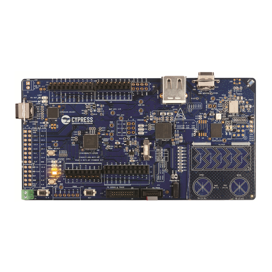
Page 43: Appendix C. Cypress Iot Development Tools
CY8CKIT-062-WiFi-BT PSoC 6 WiFi-BT Pioneer Kit The PSoC 6 WiFi-BT Pioneer Kit shown in Figure 39 is a development kit from Cypress that supports the PSoC 6 MCU family of devices. The following are the features of the PSoC 6 WiFi-BT Pioneer kit baseboard: ... - Page 44 Getting Started with PSoC 6 MCU Document History Document Title: AN221774 – Getting Started with PSoC 6 MCU Document Number: 002-21774 Orig. of Submission Revision Description of Change Change Date SNVN, 6049560 03/28/2018 New application note VKVK www.cypress.com Document No. 002-21774 Rev. **...
- Page 45 Cypress is not liable, in whole or in part, and you shall and hereby do release Cypress from any claim, damage, or other liability arising from or related to all Unintended Uses of Cypress products.
Need help?
Do you have a question about the CY8CKIT-062-WiFi-BT and is the answer not in the manual?
Questions and answers