
Related Manuals for Cypress CY8CKIT-044


Summary of Contents for Cypress CY8CKIT-044
- Page 1 CY8CKIT-044 ® PSoC 4 M-Series Pioneer Kit Guide Doc. No. 001-96598 Rev. *C Cypress Semiconductor 198 Champion Court San Jose, CA 95134-1709 www.cypress.com Arrow.com. Downloaded from...
- Page 2 Cypress is not liable, in whole or in part, and you shall and hereby do release Cypress from any claim, damage, or other liability arising from or related to all Unintended Uses of Cypress products.
-
Page 3: Table Of Contents
Example Projects ................................. 23 Using the Kit Example Projects ........................... 23 µC/Probe™ Projects ......................25 ® Using the Micrium Deep-Sleep Blinky ............................... 25 CY8CKIT-044 PSoC® 4 M-Series Pioneer Kit Guide, Doc. No. 001-96598 Rev. *C Arrow.com. Arrow.com. Arrow.com. Downloaded from Downloaded from... - Page 4 A.3.10 3-Axis Accelerometer ..........................52 A.3.11 PWM Temperature Sensor ........................53 A.3.12 Ambient Light Sensor ..........................53 A.3.13 Serial Interconnection Between PSoC 5LP and PSoC 4200M ............... 53 CY8CKIT-044 PSoC® 4 M-Series Pioneer Kit Guide, Doc. No. 001-96598 Rev. *C Arrow.com. Arrow.com. Arrow.com.
- Page 5 On-Board Peripherals ..........................61 A.6. KitProg Status LED States ..........................62 A.7. Bill of Materials ..............................63 Revision History ................................... 67 Document Revision History ............................67 CY8CKIT-044 PSoC® 4 M-Series Pioneer Kit Guide, Doc. No. 001-96598 Rev. *C Arrow.com. Arrow.com. Arrow.com. Arrow.com.
-
Page 6: Safety Information
Handling Boards CY8CKIT-044 board is sensitive to ESD. Hold the board only by its edges. After removing the board from its box, place it on a grounded, static-free surface. Use a conductive foam pad if available. Do not slide the board over any surface. -
Page 7: Introduction
3.3 V or 5 V. You will use PSoC Creator™ to develop and debug your PSoC 4200M device projects. PSoC Creator is Cypress’ standard integrated design environment (IDE). If you are new to PSoC Creator, see the documentation on the PSoC Creator home AN79953 –... -
Page 8: Board Details
Introduction Figure 1-1. Kit Contents Inspect the contents of the kit; if you find any part missing, contact your nearest Cypress sales office for help: www.cypress.com/go/support. 1.2 Board Details The PSoC 4 M-Series Pioneer Kit consists of the following blocks, as shown in Figure 1-2. - Page 9 Introduction Figure 1-2. PSoC 4 M-Series Pioneer Kit Markup CY8CKIT-044 PSoC® 4 M-Series Pioneer Kit Guide, Doc. No. 001-96598 Rev. *C Arrow.com. Arrow.com. Arrow.com. Arrow.com. Arrow.com. Arrow.com. Arrow.com. Arrow.com. Arrow.com. Downloaded from Downloaded from Downloaded from Downloaded from Downloaded from...
-
Page 10: Psoc Creator
PSoC Creator also enables you to tap into an entire tool ecosystem with integrated compiler chains and production programmers for PSoC devices. For more information, visit www.cypress.com/psoccreator. CY8CKIT-044 PSoC® 4 M-Series Pioneer Kit Guide, Doc. No. 001-96598 Rev. *C Arrow.com. Arrow.com. -
Page 11: Psoc Creator Code Examples
Create new workspace for the example project. This can speed up your design process by starting you off with a complete, basic design. You can then adapt that design to your application. Figure 1-5. Code Example Projects with Sample Code CY8CKIT-044 PSoC® 4 M-Series Pioneer Kit Guide, Doc. No. 001-96598 Rev. *C Arrow.com. Arrow.com. -
Page 12: Kit Example Projects
Document Manager: PSoC Creator provides a document manager to help you easily find and access the document resources. To open the document manager, choose the menu item Help > Document Manager. 1.4 Getting Started This guide will help you be acquainted with the CY8CKIT-044 PSoC 4 M-Series Pioneer Kit: Installation chapter describes the installation of the kit software. -
Page 13: Technical Support
Times New Roman Displays an equation: 2 + 2 = 4 Text in gray boxes Describes Cautions or unique functionality of the product. CY8CKIT-044 PSoC® 4 M-Series Pioneer Kit Guide, Doc. No. 001-96598 Rev. *C Arrow.com. Arrow.com. Arrow.com. Arrow.com. Arrow.com. -
Page 14: Acronyms
Red Green Blue Successive Approximation Register Serial Peripheral Interface Serial Wire Debug Universal Asynchronous Receiver UART Transmitter Universal Serial Bus CY8CKIT-044 PSoC® 4 M-Series Pioneer Kit Guide, Doc. No. 001-96598 Rev. *C Arrow.com. Arrow.com. Arrow.com. Arrow.com. Arrow.com. Arrow.com. Arrow.com. Arrow.com. -
Page 15: Installation
2. Installation This chapter describes the steps to install the software tools and packages on a PC for using the CY8CKIT-044 PSoC 4 M- Series Pioneer Kit. This includes the IDE on which the projects will be built and used for programming. - Page 16 Figure 2-1. Kit Installer Screen Select the folder in which you want to install the CY8CKIT-044 kit-related files. Choose the directory and click Next. When you click Next, the CY8CKIT-044 installer automatically installs the required software, if it is not present on your computer.
-
Page 17: Uninstall Software
2.3 Uninstall Software The software can be uninstalled using one of the following methods: Go to Start > All Programs > Cypress > Cypress Update Manager and select the Uninstall button that corresponds to the kit software. Go to Start > Control Panel > Programs and Features for Windows 7 or Add/Remove Programs for Windows XP;... -
Page 18: Kit Operation
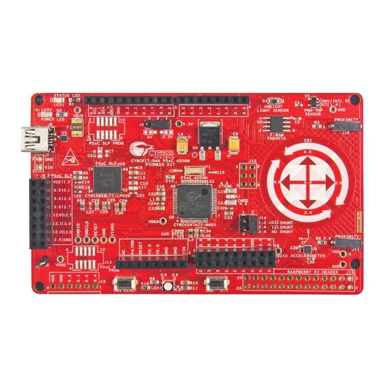
PSoC 4200M device. Refer to the PSoC 4200M datasheet for details on device features. Figure 3-1. PSoC 4200M Block Diagram CY8CKIT-044 PSoC® 4 M-Series Pioneer Kit Guide, Doc. No. 001-96598 Rev. *C Arrow.com. Arrow.com. - Page 19 RGB LED Push Button PSoC 4200M Arduino Compatible Input/Output Headers Digilent Pmod Compatible Header Rapsberry Pi Compatible Header Figure 3-3. PSoC 4 M-Series Pioneer Kit Board Diagram CY8CKIT-044 PSoC® 4 M-Series Pioneer Kit Guide, Doc. No. 001-96598 Rev. *C Arrow.com. Arrow.com. Arrow.com. Arrow.com.
- Page 20 3.3 V. KitProg: The KitProg is a multi-functional system, which includes a programmer, debugger, USB-I2C bridge, and a USB-UART bridge. Refer to the KitProg User Guide in the installation folder <Install_Directory>\CY8CKIT-044 PSoC 4 M-Series Pioneer Kit\<version>\Documentation\KitProg_User_Guide.pdf for more details on the KitProg.
-
Page 21: Kitprog
20. F-RAM: This kit features a Cypress F-RAM device of 1 Mb capacity. The F-RAM is connected to the I2C interface of the PSoC 4200M device. The Cypress F-RAM device can be used similar to an external EEPROM memory for data logging operations. -
Page 22: Debugging Using Psoc Creator
The KitProg firmware normally does not require any update. You can use the PSoC Programmer software to update the KitProg firmware. Refer to the KitProg User Guide for a detailed explanation on how to update the KitProg firmware. CY8CKIT-044 PSoC® 4 M-Series Pioneer Kit Guide, Doc. No. 001-96598 Rev. *C Arrow.com. Arrow.com. Arrow.com. -
Page 23: Example Projects
4.1 Using the Kit Example Projects To access the example projects, download and install the CY8CKIT-044 PSoC 4 M-Series Pioneer Kit setup file from the kit page. After installation, the example projects are available in the Firmware folder in the installation directory. - Page 24 OK to exit the window and start programming, as shown in Figure 4-3. Figure 4-3. Connect Device From PSoC Creator and Program CY8CKIT-044 PSoC® 4 M-Series Pioneer Kit Guide, Doc. No. 001-96598 Rev. *C Arrow.com. Arrow.com. Arrow.com.
-
Page 25: Using The Micrium Μc/Probe™ Projects
Watch to graphically visualize the internals of any embedded system. With µC/Probe, you can test your embedded design effortlessly, with a few mouse clicks. Cypress provides pre-designed µC/Probe project (workspace) files for all the example projects associated with the PSoC 4 M-Series Pioneer Kit except the Deep-Sleep Blinky example project. -
Page 26: Capsense Proximity
4-6, and press the reset switch (SW1) of the kit. You should bend the wire to form a loop, as shown in Figure 4-5 to get better proximity range. CY8CKIT-044 PSoC® 4 M-Series Pioneer Kit Guide, Doc. No. 001-96598 Rev. *C Arrow.com. Arrow.com. Arrow.com. -
Page 27: Proximity Gestures
60% when ILO is used as the clock source for LFCLK. Use the ILO Trim Component as demonstrated in the Deep- Sleep Blinky project to achieve higher accuracy with ILO. CY8CKIT-044 PSoC® 4 M-Series Pioneer Kit Guide, Doc. No. 001-96598 Rev. *C Arrow.com. Arrow.com. Arrow.com. - Page 28 Table 4-1. Gestures and Actions Gesture Action (LED Color Change) Red > Green > Blue > Red DOWN Red > Blue > Green > Red CY8CKIT-044 PSoC® 4 M-Series Pioneer Kit Guide, Doc. No. 001-96598 Rev. *C Arrow.com. Arrow.com. Arrow.com. Arrow.com. Arrow.com.
-
Page 29: Hardware Connections
Red > Blue >Green > Red, one color at a time with each wave. Power consumed by PSoC 4200M for this project can be measured using an ammeter as described in the Deep-Sleep Blinky project. CY8CKIT-044 PSoC® 4 M-Series Pioneer Kit Guide, Doc. No. 001-96598 Rev. *C Arrow.com. Arrow.com. Arrow.com. Arrow.com. -
Page 30: Touch Gestures
Swipe Clockwise Orange > Red > Violet Red > Orange > Yellow > Green > Blue > Swipe Counter-clockwise Indigo > Violet > Red CY8CKIT-044 PSoC® 4 M-Series Pioneer Kit Guide, Doc. No. 001-96598 Rev. *C Arrow.com. Arrow.com. Arrow.com. Arrow.com. - Page 31 Deep- Sleep Blinky project to achieve higher accuracy with ILO. Note: Clockwise and counter-clockwise gestures can be initiated from any sensor except sensor 5. CY8CKIT-044 PSoC® 4 M-Series Pioneer Kit Guide, Doc. No. 001-96598 Rev. *C Arrow.com. Arrow.com. Arrow.com. Arrow.com.
-
Page 32: Hardware Connections
PSoC 4200M turns the LED back on and switches to the 10ms scan interval mode. Power consumed by PSoC 4200M for this project can be measured using an ammeter as described in the Deep-Sleep Blinky project. CY8CKIT-044 PSoC® 4 M-Series Pioneer Kit Guide, Doc. No. 001-96598 Rev. *C Arrow.com. Arrow.com. Arrow.com. Arrow.com. -
Page 33: Accelerometer
Figure 4-12 shows the accelerometer orientation with respect to the kit. Figure 4-12. Accelerometer Movement in X-Axis Figure 4-13 Accelerometer Movement in Y-Axis CY8CKIT-044 PSoC® 4 M-Series Pioneer Kit Guide, Doc. No. 001-96598 Rev. *C Arrow.com. Arrow.com. Arrow.com. Arrow.com. -
Page 34: Hardware Connections
The firmware also reads back the data logged to the F-RAM every one second and sends it through a UART. This data can be read using the KitProg USB-UART bridge. Refer to the KitProg User Guide to learn how to use the KitProg USB-UART bridge. CY8CKIT-044 PSoC® 4 M-Series Pioneer Kit Guide, Doc. No. 001-96598 Rev. *C Arrow.com. Arrow.com. Arrow.com. Arrow.com. -
Page 35: Hardware Connections
Figure 4-15. Locate the .elf file for Sensor Hub Project Click on the Settings button from the toolbar and select Cypress PSoC Prog under the Communication tab in the Settings window. Select the KitProg in the drop-down corresponding to the option Port, and click OK. Refer to step 9 of... - Page 36 Stop bits as ‘1’, and Flow Control option to ‘None’. Observe that the data written to the F-RAM is read back and displayed in the COM terminal software, as shown in Figure 4-19. CY8CKIT-044 PSoC® 4 M-Series Pioneer Kit Guide, Doc. No. 001-96598 Rev. *C Arrow.com. Arrow.com. Arrow.com.
- Page 37 Panel tool to read the F-RAM data log, reset the PSoC 4 M-Series Pioneer Kit before using the µC/Probe to view the data. If the COM terminal software is connected while µC/Probe is running, it displays an error message to indicate communication failure. CY8CKIT-044 PSoC® 4 M-Series Pioneer Kit Guide, Doc. No. 001-96598 Rev. *C Arrow.com. Arrow.com.
-
Page 38: Raspberry Pi
Type “startx” at the command prompt to enter the graphical user interface. Double-click on LXTerminal on the desktop to open the terminal program. Install Minicom to view the serial data coming from CY8CKIT-044 by typing “sudo apt-get install minicom”. Wait until the minicom gets installed. -
Page 39: Appendix
Appendix A. Appendix A.1. Schematics Figure A-1. PSoC 4200M Schematic CY8CKIT-044 PSoC® 4 M-Series Pioneer Kit Guide, Doc. No. 001-96598 Rev. *C Arrow.com. Arrow.com. Arrow.com. Arrow.com. Arrow.com. Arrow.com. Arrow.com. Arrow.com. Arrow.com. Arrow.com. Arrow.com. Arrow.com. Arrow.com. Arrow.com. Arrow.com. Arrow.com. Arrow.com. Arrow.com. - Page 40 Appendix Figure A-2. KitProg (PSoC 5LP) and Programming Interface Schematic CY8CKIT-044 PSoC® 4 M-Series Pioneer Kit Guide, Doc. No. 001-96598 Rev. *C Arrow.com. Arrow.com. Arrow.com. Arrow.com. Arrow.com. Arrow.com. Arrow.com. Arrow.com. Arrow.com. Arrow.com. Arrow.com. Arrow.com. Arrow.com. Arrow.com. Arrow.com. Arrow.com. Arrow.com. Arrow.com.
- Page 41 Appendix Figure A-3. Power Supply and Power Monitoring Circuit Schematic CY8CKIT-044 PSoC® 4 M-Series Pioneer Kit Guide, Doc. No. 001-96598 Rev. *C Arrow.com. Arrow.com. Arrow.com. Arrow.com. Arrow.com. Arrow.com. Arrow.com. Arrow.com. Arrow.com. Arrow.com. Arrow.com. Arrow.com. Arrow.com. Arrow.com. Arrow.com. Arrow.com. Arrow.com. Arrow.com.
- Page 42 Appendix Figure A-4. Peripheral Schematic CY8CKIT-044 PSoC® 4 M-Series Pioneer Kit Guide, Doc. No. 001-96598 Rev. *C Arrow.com. Arrow.com. Arrow.com. Arrow.com. Arrow.com. Arrow.com. Arrow.com. Arrow.com. Arrow.com. Arrow.com. Arrow.com. Arrow.com. Arrow.com. Arrow.com. Arrow.com. Arrow.com. Arrow.com. Arrow.com. Arrow.com. Arrow.com. Arrow.com. Arrow.com. Arrow.com.
-
Page 43: Using The Micrium Μc/Probe
µC/Probe License Card for the µC/Probe license key. To activate the license, click on File > Activation. In the License Manager window, type in the license key and press Activate as shown in Figure A-6. Figure A-6. µC/Probe Activation CY8CKIT-044 PSoC® 4 M-Series Pioneer Kit Guide, Doc. No. 001-96598 Rev. *C Arrow.com. Arrow.com. Arrow.com. - Page 44 PSoC Creator. To link the .elf file, click the ELF button in the Symbol Browser and navigate to the project .elf file. The .elf file of a project is located at: <Project Directory>\<Project Name.cydsn>\CortexM0\<Compiler Version>\<Debug> or <Release>\<Project Name.elf>. Figure A-8. Add New Symbol File CY8CKIT-044 PSoC® 4 M-Series Pioneer Kit Guide, Doc. No. 001-96598 Rev. *C Arrow.com. Arrow.com. Arrow.com.
- Page 45 You can click on the graphical elements to bring up the settings for each individual graphical element, as shown in Figure A-10. Figure A-10. Settings for Graphical Elements CY8CKIT-044 PSoC® 4 M-Series Pioneer Kit Guide, Doc. No. 001-96598 Rev. *C Arrow.com. Arrow.com. Arrow.com.
- Page 46 Select the File menu of the µC/Probe and click Settings. Figure A-11. µC/Probe Settings 10. Select the Communication tab from the Settings window. Click the Cypress PSoC Prog option and select the KitProg/<serial number> from the drop-down menu. Select OK to close the dialog box.
- Page 47 Ambient Light Sensor Data Timestamp Information from RTC RGB LED Control Using Color Palette Temperature Sensor Data Accelerometer Data CY8CKIT-044 PSoC® 4 M-Series Pioneer Kit Guide, Doc. No. 001-96598 Rev. *C Arrow.com. Arrow.com. Arrow.com. Arrow.com. Arrow.com. Arrow.com. Arrow.com. Arrow.com. Arrow.com.
-
Page 48: Hardware Functional Description
(near DC voltages) to ultrasonic signals. For more information, visit the PSoC 5LP web page. Also, refer to the CY8C58LPxx Family Datasheet. CY8CKIT-044 PSoC® 4 M-Series Pioneer Kit Guide, Doc. No. 001-96598 Rev. *C Arrow.com. Arrow.com. Arrow.com. Arrow.com. Arrow.com. -
Page 49: Power System
ORing diodes prevent damage to components when the board is powered from different voltage sources at the same time. ESD protection is provided for the USB Mini-B connector. CY8CKIT-044 PSoC® 4 M-Series Pioneer Kit Guide, Doc. No. 001-96598 Rev. *C Arrow.com. Arrow.com. Arrow.com. - Page 50 4 of J14. Connect the negative terminal of the external voltage supply to and GND pin on the board. Figure A-20 shows the required connections. CY8CKIT-044 PSoC® 4 M-Series Pioneer Kit Guide, Doc. No. 001-96598 Rev. *C Arrow.com. Arrow.com. Arrow.com.
-
Page 51: Expansion Connectors
This header is not populated on the PSoC 4 M-Series Pioneer board. You must populate this header before connecting Pmod Peripheral Modules. Refer to the “No Load Components” section of the Bill of Materials for the header part number. CY8CKIT-044 PSoC® 4 M-Series Pioneer Kit Guide, Doc. No. 001-96598 Rev. *C Arrow.com. Arrow.com. Arrow.com. -
Page 52: Usb Mini-B Connector
The accelerometer is assigned with the I2C address 0x0F. Refer to the KXTJ2-1009 Datasheet for more information on how to configure the accelerometer. CY8CKIT-044 PSoC® 4 M-Series Pioneer Kit Guide, Doc. No. 001-96598 Rev. *C Arrow.com. Arrow.com. Arrow.com. -
Page 53: Pwm Temperature Sensor
PSoC 5LP for enabling SPI communication between PSoC 5LP and PSoC 4200M for custom PSoC 5LP applications. Figure A-21. Schematics of Serial Interface Connections and I2C Pull-Up via FET CY8CKIT-044 PSoC® 4 M-Series Pioneer Kit Guide, Doc. No. 001-96598 Rev. *C Arrow.com. -
Page 54: Raspberry Pi Compatible Header
3.3-V domain regardless of the power settings on the PSoC 4 M-Series Pioneer Kit. Figure A-22. PSoC 4 M-Series Pioneer Kit Connected to a Raspberry Pi Model B CY8CKIT-044 PSoC® 4 M-Series Pioneer Kit Guide, Doc. No. 001-96598 Rev. *C Arrow.com. -
Page 55: Level Translators
Raspberry Pi. This level translator also connects to the 3-Axis accelerometer and the Cypress F-RAM device. The level translator, which interfaces SPI lines of PSoC 4200M to the Raspberry Pi, is switched on automatically when a Raspberry Pi is connected to the PSoC 4 M-Series Pioneer Kit. -
Page 56: Test Points
Figure A-24. SWD Programming Pins Brought as Test Points All power domains (VDDA, VDDD, and VDDIO) including VIN, 3.3V and GND are also brought as test points for easy probing. CY8CKIT-044 PSoC® 4 M-Series Pioneer Kit Guide, Doc. No. 001-96598 Rev. *C Arrow.com. Arrow.com. -
Page 57: Using Fm24V10 F-Ram
Figure A-26 Figure A-27 provide a snapshot of the write/read packet structure as a quick reference. Figure A-26. F-RAM Single-Byte and Multiple-Byte Write Packet Structure CY8CKIT-044 PSoC® 4 M-Series Pioneer Kit Guide, Doc. No. 001-96598 Rev. *C Arrow.com. Arrow.com. Arrow.com. - Page 58 Bridge Control Panel (BCP) software similar to the way you communicate with any other I2C slave device. Refer to the KitProg User Guide for more details on how to use the BCP to communicate with an I2C slave device. CY8CKIT-044 PSoC® 4 M-Series Pioneer Kit Guide, Doc. No. 001-96598 Rev. *C Arrow.com.
-
Page 59: Migrating Projects Across Different Pioneer Series Kits
A.5. Migrating Projects Across Different Pioneer Series Kits All Cypress Pioneer series kits are Arduino Uno compatible and have some common on-board peripherals such as RGB LED, CapSense and User Switch. However, the pin mapping in each of the boards is different due to differences in pin functions of the PSoC device used. - Page 60 P3[5] P4[0] * These pins are also used for on-board peripherals. Refer to the tables in the On-Board Peripherals section for connection details. CY8CKIT-044 PSoC® 4 M-Series Pioneer Kit Guide, Doc. No. 001-96598 Rev. *C Arrow.com. Arrow.com. Arrow.com. Arrow.com. Arrow.com.
-
Page 61: On-Board Peripherals
Table A - 8. User Switch Pin Map Pioneer Series Kits Arduino Pin CY8CKIT-042 CY8CKIT-040 CY8CKIT-042-BLE CY8CKIT-044 P0[7] P2[7] P0[7] CY8CKIT-044 PSoC® 4 M-Series Pioneer Kit Guide, Doc. No. 001-96598 Rev. *C Arrow.com. Arrow.com. Arrow.com. Arrow.com. Arrow.com. Arrow.com. Arrow.com. Arrow.com. Arrow.com. Arrow.com. -
Page 62: Kitprog Status Led States
This may happen if the kit is not powered from the USB host. LED is OFF Power LED is ON Verify the USB cable and check if PSoC Programmer is installed on the PC. CY8CKIT-044 PSoC® 4 M-Series Pioneer Kit Guide, Doc. No. 001-96598 Rev. *C Arrow.com. Arrow.com. Arrow.com. Arrow.com. -
Page 63: Bill Of Materials
Protectron 8X2 RECP P9403-16-21 16PS.1" DL GOLD Electromech CONN HEADR Protectron 3p_jumper BRKWAY .100 3POS P9101-03-12-1 Electromech CY8CKIT-044 PSoC® 4 M-Series Pioneer Kit Guide, Doc. No. 001-96598 Rev. *C Arrow.com. Arrow.com. Arrow.com. Arrow.com. Arrow.com. Arrow.com. Arrow.com. Arrow.com. Arrow.com. Arrow.com. Arrow.com. - Page 64 RES SMD 1 OHM 1% Stackpole 1 ohm RMCF1206FT1R00 1/4W 1206 Electronics Inc SW1,SW2 SWITCH TACTILE Panasonic - ECG EVQ-PE105K CY8CKIT-044 PSoC® 4 M-Series Pioneer Kit Guide, Doc. No. 001-96598 Rev. *C Arrow.com. Arrow.com. Arrow.com. Arrow.com. Arrow.com. Arrow.com. Arrow.com. Arrow.com. Arrow.com.
- Page 65 0.1 uFd TDK Corporation C1005X5R1A104K050BA CERAMIC Y5V 0402 CAP CERAMIC 1.0UF 1.0 uFd Taiyo Yuden TMK107BJ105KA-T 25V X5R 0603 10% CY8CKIT-044 PSoC® 4 M-Series Pioneer Kit Guide, Doc. No. 001-96598 Rev. *C Arrow.com. Arrow.com. Arrow.com. Arrow.com. Arrow.com. Arrow.com. Arrow.com. Arrow.com.
- Page 66 TVS1,TVS2 5V 350W Dioded Inc. SD05-7 SOD-323 RES 0.0 OHM 1/8W R7,R56,R57 ZERO Panasonic-ECG ERJ-6GEY0R00V 0805 SMD CY8CKIT-044 PSoC® 4 M-Series Pioneer Kit Guide, Doc. No. 001-96598 Rev. *C Arrow.com. Arrow.com. Arrow.com. Arrow.com. Arrow.com. Arrow.com. Arrow.com. Arrow.com. Arrow.com. Arrow.com. Arrow.com.
-
Page 67: Revision History
Added 4.9 Raspberry Updated Table A - Updated Figure A-22. 05/11/2017 GNKK Updated the Cypress logo and copyright information. CY8CKIT-044 PSoC® 4 M-Series Pioneer Kit Guide, Doc. No. 001-96598 Rev. *C Arrow.com. Arrow.com. Arrow.com. Arrow.com. Arrow.com. Arrow.com. Arrow.com. Arrow.com. Arrow.com.
Need help?
Do you have a question about the CY8CKIT-044 and is the answer not in the manual?
Questions and answers