Sign In
Upload
Download
Table of Contents
Contents
Add to my manuals
Delete from my manuals
Share
URL of this page:
HTML Link:
Bookmark this page
Add
Manual will be automatically added to "My Manuals"
Print this page
×
Bookmark added
×
Added to my manuals
Manuals
Brands
Sullair Manuals
Air Compressor
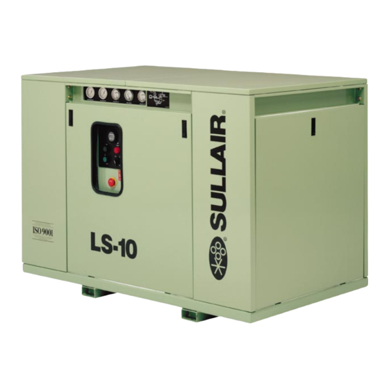
LS-10 25HP 24KT
Operators manual and parts lists
Sullair LS-10 25HP Operators Manual And Parts Lists
Industrial air compressor
Hide thumbs
1
2
Table Of Contents
3
4
5
6
7
8
9
10
11
12
13
14
15
16
17
18
19
20
21
22
23
24
25
26
27
28
29
30
31
32
33
34
35
36
37
38
39
40
41
42
43
44
45
46
47
48
49
50
51
52
53
54
55
56
57
58
59
60
61
62
63
64
65
66
67
68
69
70
71
72
73
74
75
76
77
78
79
80
81
82
83
84
85
86
87
88
89
90
page
of
90
Go
/
90
Contents
Table of Contents
Troubleshooting
Bookmarks
Table of Contents
Table of Contents
Safety
General
Personal Protective Equipment
Pressure Release
Fire and Explosion
Moving Parts
Hot Surfaces, Sharp Edges and Sharp Corners
Toxic and Irritating Substances
Electrical Shock
Lifting
Entrapment
Description
Introduction
Description of Components
Sullair Compressor Unit, Functional Description
Compressor Cooling and Lubrication System, Functional Description
Compressor Discharge System, Functional Description
Control System, Functional Description
Control System, Functional Description
Supervisor
Air Inlet System, Functional Description
Instrument Panel Group
Specifications
Table of Specifications
Lubrication Guide
Application Guide
Lubrication Change Recommendations and Maintenance
Installation
Mounting of Compressor
Ventilation and Cooling
Service Air Piping
Coupling Alignment Check
Fluid Level Check
18 4.6 Electrical Preparation
Electrical Preparation
Motor Rotation Direction Check
General
Purpose of Controls
Initial Start
Subsequent Start
General Introduction
Supervisor II Parameter Setup
Operating the Compressor
Purpose of Controls
Supervisor II Output Relays
Subsequent Start
Shutdown Procedure
Keypad
Status Displays
Lamp Indicators
General
Daily Operation
Maintenance after Inital 50 Hours of Operation
Maintenance Every 1000 Hours
Fluid Maintenance
Filter Maintenance
Separator Maintenance
Parts Replacement and Adjustment Procedures
Troubleshooting
Calibration
Procedure for Ordering Parts
Recommended Spare Parts List
Motor, Compressor, Frame and Parts
Cooler Assembly
Air Inlet System
Cooling and Lubrication System
Discharge System
Control System and Electrical Parts
Instrument Panel
Enclosure
Decal Group
Wiring Diagram
Wiring Diagram
Wiring Diagram
Advertisement
Quick Links
1
Table of Specifications
2
Parts Replacement and Adjustment Procedures
Download this manual
INDUSTRIAL AIR
COMPRESSOR
LS---10
25, 30 & 40 HP
18, 22 & 30 KW
STANDARD & 24 KT
OPERATOR'S
MANUAL AND
PARTS LIST
KEEP FOR
FUTURE
REFERENCE
Part Number 02250105--- 114
eSullair Corporation
Table of
Contents
Previous
Page
Next
Page
1
2
3
4
5
Advertisement
Table of Contents
Need help?
Do you have a question about the LS-10 25HP and is the answer not in the manual?
Ask a question
Questions and answers
Related Manuals for Sullair LS-10 25HP
Air Compressor Sullair LS16T Operators Manual And Parts Lists
Industrial air compressor. 100-200hp/ 75-149kw supervisor ii (113 pages)
Air Compressor Sullair LS-120 series Operators Manual And Parts Lists
Industrial air compressor. 40, 50, 60, 75 & 100hp/ 37, 45, 56 & 75kw air-cooled & water-cooled std & 24kt (130 pages)
Air Compressor Sullair LS-160 series Operators Manual And Parts Lists
Industrial air compressor. 40, 50, 60, 75 & 100hp/ 37, 45, 56 & 75kw air-cooled & water-cooled std & 24kt (130 pages)
Air Compressor Sullair LS-100L Operator's Manual
Ls-100 series industrial air compressor 25, 30 & 40 hp/ 18, 22 & 30 kw standard & 24 kt air-cooled and water-cooled (122 pages)
Air Compressor Sullair LS16 Operator's Manual
Electro-mechanical controller (36 pages)
Air Compressor Sullair LS-12 Operators Manual And Parts Lists
Industrial air compressor. 40, 50, 60, 75 & 100hp (30, 37, 45, 55 & 75kw) standard & 24 kt (112 pages)
Air Compressor Sullair LS-12 Operator's Manual
Industrial air compressor (137 pages)
Air Compressor Sullair LS-10 30HP 24KT Operators Manual And Parts Lists
Industrial air compressor (90 pages)
Air Compressor Sullair LS-10 18KW 24KT Operators Manual And Parts Lists
Industrial air compressor (90 pages)
Air Compressor Sullair LS-10 22KW 24KT Operators Manual And Parts Lists
Industrial air compressor (90 pages)
Air Compressor Sullair LS-10 30KW 24KT Operators Manual And Parts Lists
Industrial air compressor (90 pages)
Air Compressor Sullair LS-10 40HP 24KT Operators Manual And Parts Lists
Industrial air compressor (90 pages)
Air Compressor Sullair LS25S-250 Operation & Maintenance Manual
Stationary screw compressor (54 pages)
Air Compressor Sullair LS-200S Operator's Manual And Parts List
Industrial air compressor (148 pages)
Air Compressor Sullair LS-20S Operator's Manual And Parts List
Industrial air compressor (102 pages)
Air Compressor Sullair LS-25 Operator's Manual And Parts List
Industrial air compressor 150-200hp/ 112-149kw air-cooled and water-cooled standard & 24kt (120 pages)
This manual is also suitable for:
Ls-10 30hp
Ls-10 18kw
Ls-10 22kw
Ls-10 30kw
Ls-10 40hp
Ls-10 30hp 24kt
...
Show all
Ls-10 25hp 24kt
Ls-10 40hp 24kt
Ls-10 18kw 24kt
Ls-10 22kw 24kt
Ls-10 30kw 24kt
Table of Contents
Save PDF
Print
Rename the bookmark
Delete bookmark?
Delete from my manuals?
Login
Sign In
OR
Sign in with Facebook
Sign in with Google
Upload manual
Upload from disk
Upload from URL


Need help?
Do you have a question about the LS-10 25HP and is the answer not in the manual?
Questions and answers