
Related Manuals for Mountup MU5001


Summary of Contents for Mountup MU5001
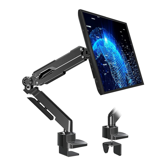
- Page 1 Premium Single Monitor Mount Instruction Manual 75x75 MU5001 32" 100x100 (1~10kg) each arm V2.0 (2.2~22lbs) each arm If you have any questions , please contact us.
-
Page 2: Package Contents
WARNING! If you do not understand these instructions or have doubts about the safety, assembly or use of this product, please contact us. Before assembly, verify all parts are included and undamaged. Improper installation may cause damage or serious injury. Do not use this product for any purpose that is not explicitly speci ed in this manual. Do not exceed weight capacity. -
Page 3: Assembly Steps
ASSEMBLY STEPS STEP 1: Apply Pads to the Bottom of Base Checklist D (x1) Assembled Base Apply pads (G) to the G (x4) Assembled Base (D) bottom to avoid desk scratches. STEP 2: Clamp Installation OR Grommet Base Installation OPTION A: Clamp Installation Mount the Assembled Base (D) on the desktop by tightening the Short Bolt (D3) with 6mm Allen Key (J) provided. - Page 4 STEP 2: (Continued) OPTION B: Grommet Base Installation Remove the Bottom Plate (D1), Short Bolt (D3) and the Base (D2) from Assembled Base (D). Insert Long Bolt (E) through the Base (D2), grommet hole in desktop and Bottom Plate (D1). Secure the Assembled Base (D) on the desktop by tightening the Long Bolt (E) with 6mm Allen Key (J).
-
Page 5: Step 3: Arm Installation
STEP 3: Arm Installation Install the lower arm (B) and the upper arm (A) to the base (D). Secure the arm by tightening the inside screw using 3mm Allen key (I). Checklist A (x1) Upper Arm B (x1) Lower Arm D (x1) Assembled Base I (x1) - Page 6 STEP 4: Attach Monitor OPTION A: Flat Back Monitor Attach the VESA plate (C) to back of monitor and secure it with screws (M-A) or (M-C) and washers Checklist (M-E) using Screwdriver. Do not tighten the screws C (x1) VESA Plate excessively or it might damage your monitor.
- Page 7 STEP 5: Hang Monitor Slide the monitor onto the head of swivel arm, install the security bolt (H). Make sure the security bolt is installed before you rotate the monitor. Checklist H (x1) security bolt Important Notice: The gas spring is pre-set to minimum tension. Once the monitor is hanged on, hold the monitor with both hands and DO NOT let go suddenly or immediately.
-
Page 8: Step 6: Adjust Tension
STEP 6: Adjust Tension For proper functioning of this mount, depending on di erent weight of monitor you might need to adjust tension in (A) using 6 mm allen key (J). upper arm Checklist J (x1) 6mm Allen Key CAUTION Note1: Be sure to keep the arm in horizontal position during adjustment. -
Page 9: Step 7: Cable Management
STEP 7: Cable Management STEP 5: (Continued) Let the cables get through the base, then press the cables close to the bottom of the arms. Attach the Plastic Cover to keep it clean and tidy. Checklist F (x1) Plastic Cover I (x1) 3mm Allen Key J (x1) - Page 10 Adjust as Desired Adjust monitor position and rotation. 180° +90° 360° 360° 360° Note: When tilted, if the monitor sags or does not stay, please fasten the tilting bolt on the mount until the monitor can be held at any angle as needed. DESK DESK Pay attention while clamp install !
-
Page 11: Product Dimensions
Product Dimensions 180° 360° 360° 8.7"-11.7" 1.9“ 5.8"... - Page 12 CAUTION AND MAINTENANCE: • Never allow children to climb, stand, hang, or play on any part of monitor or stand. • This product is intended for indoor use only. Using this product outdoors could lead to product failure and personal injury. •...
Need help?
Do you have a question about the MU5001 and is the answer not in the manual?
Questions and answers