
Subscribe to Our Youtube Channel
Related Manuals for FSR DV-HSW-21CEC


Summary of Contents for FSR DV-HSW-21CEC
- Page 1 User Manual DV-HSW-21CEC HDMI 2x1 Switcher Based on firmware 02.07 DV-MFSW-21CEC HDMI / VGA 2x1 Switcher Based on firmware 02.07 43098 LIT1566C...
-
Page 2: Important Safety Instructions
4. Do not install near any heat 9. Only use sources such as radiators, heat attachments/accessories registers, stoves, or other device specified by FSR. (including amplifiers) that produce heat. 5. Do not place sources of open 10. Refer all servicing to... -
Page 3: Table Of Contents
Table of Contents Important Safety Instructions ............... 2 Overview ......................4 Features ......................4 Package Contents ..................6 Typical Application ..................6 Front Panel ....................7 Rear Panel ....................8 Hardware Installation .................. 10 EDID Management ..................11 RS-232 Operation ..................12 RS-232 Serial Protocol ................ -
Page 4: Overview
OVERVIEW The DV-HSW-21CEC is a 2x1 HDMI switcher supporting up to 4K x 2K @ 30Hz. The DV-MFSW-21CEC is a unique switcher and a must have for installations spanning new and legacy technology. This switcher has 1 HDMI input supporting resolutions up to 4K x 2K @ 30Hz and 1 VGA (HD-15) input supporting resolutions up to 1920 x 1200 @ 60Hz. - Page 5 switching CEC SUPPORT The DV-HSW-21CEC and DV-MFSW-21CEC can automatically power-up displays that have CEC capability when a source is connected. They can also power the display off after the input signal is removed for 2 minutes. Most brands of displays need to have the CEC control enabled in the menu to allow this function to work, and of course not all displays support CEC.
-
Page 6: Package Contents
PACKAGE CONTENTS 1 x DV-MFSW-21A or DV-HSW-21A Switcher. 1 x 12VDC Power Supply 2 x Surface Mount Brackets 1 x 3.81mm Phoenix Connector (3 Pin) 1 x 3.81mm Phoenix Connector (5 Pin) TYPICAL APPLICATION DV-MFSW-21CEC model shown. DV-HSW-21A has two HDMI (no VGA) input connectors and no audio input connector HDMI Audio... -
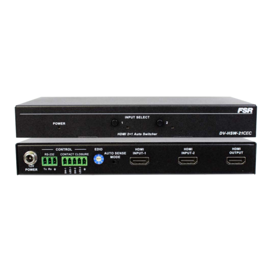
Page 7: Front Panel
FRONT PANEL DV-HSW4K-21CEC / DV-MFSW-21CEC Name Description Power LED Lit when power is on Select Button Press to select HDMI IN as input source Indicator Lit when Source is selected Press to select VGA or HDMI on Select Button DV-HSW-21A as input source Indicator Lit when VGA is selected... -
Page 8: Rear Panel
REAR PANEL DV-MFSW-21CEC model shown. DV-HSW-21CEC has two HDMI (no VGA) input connectors and no audio input connector Name Description Power 12VDC power input RS232 control. RS232 For the API commands, please refer to DV- MFSW-21CEC or DV-HSW-21CEC RS-232 Serial Protocol Connects to a control device such as keypad for switching between HDMI IN 1 and PC IN 2. - Page 9 Switching occurs regardless of input signal state. Connects to an HDMI source (Two HDMI HDMI INPUT inputs on DV-HSW-21CEC model) Audio binding VGA channel, embedded in VGA + Audio HDMI signal output INPUT...
-
Page 10: Hardware Installation
HARDWARE INSTALLATION DV-MFSW-21CEC model shown. DV-HSW-21CEC has two HDMI (no VGA) input connectors and no audio input connector Connect the HDMI or VGA input source (such as DVD Player, Apple TV, and STB) to the unit. Connect the HDMI display device (such as HD-LCD) to the HDMI output port of the switcher. -
Page 11: Edid Management
1920x1080 60Hz (default) 1280x720 60Hz 1024x768 60Hz 800x600 60Hz Reserved Reserved DV-HSW-21CEC EDID for both inputs. Position Functions Automatically copy HDMI display's EDID to all HDMI Inputs, if failed, the EDID of all HDMI inputs won’t change. 4K2K 30Hz 2CH (default) -
Page 12: Rs-232 Operation
Pin 5 Ground — Ground RS-232 SERIAL PROTOCOL The DV-MFSW-21CEC and the DV-HSW-21CEC switcher may be configured or queried via the RS-232 serial connection. Request/Response Format All requests and responses will be entirely in ASCII. The requests can be in either upper or lower case. -
Page 13: Field Separators
Field Separators Fields are separated by white space, that is any number of spaces or tabs as long as the entire command is less than 80 characters. A <cr> terminates the command. Below is an example describing a command. <cr> So the actual message would look like this: CON 2<cr>... -
Page 14: Error Response
Error Response It is inevitable that errors occur in the requests sent to the switcher. If an invalid command is sent to the switcher, the switcher will respond with the message "ERR: unknown command". If an invalid parameter is sent to the switcher, the switcher will respond with the message "ERR:"... -
Page 15: Connection Request
Connection Request The connection request is used to connect one of the two available inputs to the output. A connection may be disconnected by using the DIS command (see later in document). input | "?" <cr> Syntax: CON <input | "?"><cr> Where: Connection request header input... -
Page 16: Disconnect Request
Where: HDCP High Definition Content Protection request header Response from DV-MFSW-21CEC: HDCP x Response from DV-HSW-21CEC: HDCP xx Where: x is either 0 or 1, with 0 representing that HDCP is not present and 1 representing that HDCP is present. -
Page 17: Model Request
The response for the DV-MFSW-21CEC switcher could HDCP 1<cr><lf> That is, HDCP is present on input 1. The response for the DV-HSW-21CEC switcher could HDCP 01<cr><lf> That is, HDCP is not present on input 1 and HDCP is present on input 2. -
Page 18: Reconnect Request
Reconnect Request The REC request allows the user to reconnect the disconnected output to the currently selected input. Note that the input to be reconnected is as indicated by the input LED on the front panel. The command has no effect if an input is already connected to the output. -
Page 19: Version Request
<cr> Syntax: VER<cr> Where: Version Request header Response form DV-MFSW-21CEC: VER DV-MFSW-21A <XX.xx> Response form DV-HSW-21CEC: VER DV-HSW-21A <XX.xx> Where: XX.xx XX = Major version number, xx = Minor version number Example: VER<cr> To which the DV-MFSW-21CEC switcher will respond:... -
Page 20: Auto-Switching Mode Configuration
Auto-Switching Mode Configuration The user may configure the Auto-Switching mode to either FIFO (First Signal Connected) or LIFO (Newest Signal Connected), using the Set Automode command. The format is as follows: Set Automode “LIFO”|”FIFO” <cr> Syntax: SET AUTOMODE <”LIFO”|”FIFO”> <cr> Where: SET AUTOMODE Automode Request header... -
Page 21: Auto-Switching Mode Reset
Example: AUTOMODE<cr> To which the DV-MFSW-21CEC switcher will respond: AUTOMODE “lifo”|”fifo”<cr> Auto-Switching Mode Reset The user may reset the Auto-Switching mode setting to the initial default setting (lifo), using the Reset command. The format is as follows: Reset <cr> Syntax: RESET <cr> Where: RESET Reset Request header... -
Page 22: Specifications
SPECIFICATIONS DV-HSW-21CEC / DV-MFSW-21CEC Video Input 2 x HDMI Type A 19-pin, female (DV-HSW-21) 1 VGA and 1 HDMI (DV-MFSW-21 only) Audio Input 3.5mm Stereo (DV-MFSW-21 only) Video Output 1 x HDMI Type A 19-pin, female RS-232 3 Pin Pluggable Screw Terminal... -
Page 23: Limited Warranty
FSR factory or Authorized Repair Stations. This warranty shall be cancelable by FSR at its sole discretion if the Unit has been subjected to physical abuse or has been modified in any way without written authorization from FSR.
Need help?
Do you have a question about the DV-HSW-21CEC and is the answer not in the manual?
Questions and answers