Table of Contents
Advertisement
Quick Links
Advertisement
Table of Contents

Related Manuals for FSR Eagle 200


Summary of Contents for FSR Eagle 200
- Page 1 » Eagle 200 rëÉêÛë=dìáÇÉ 43998B LIT1116A D4...
- Page 2 30 days after the transfer of risks. In the event of justified notice of compliant, FSR can repair the fault or provide a replacement at its own discretion within an appropriate period. If this measure proves to be impossible or unsuccessful, the purchaser can demand a reduction in the purchase price or cancellation of the contract.
- Page 3 Not included in the guarantee coverage are system failures which are attributed to programs or special electronic circuitry provided by the purchaser, e.g. interfaces. Normal wear as well as normal maintenance are not subject to the guarantee provided by FSR either.
- Page 4 To avoid fire hazard, use only the fuse having identical type, voltage rating, and current rating characteristics. Refer fuse replacement to qualified service personnel. aç=kçí=léÉê~íÉ=áå=bñéäçëáîÉ=^íãçëéÜÉêÉë To avoid explosion, do not operate this product in an explosive atmosphere. Eagle 200 • User’s Guide...
- Page 5 Ein Ausrufungszeichen innerhalb eines gleichwinkeligen Dreiecks dient dazu, den Benutzer auf wichtige Bedienungs-und Wartungsanweisungen in der Dem Great beiliegenden Literatur aufmerksam zu machen. Eagle 200 • User’s Guide...
- Page 6 `Ü~åÖÉ=eáëíçêó The table below lists the changes to the Eagle 200 User’s Guide. Table 0-1. Change History Date ECO # Description Approved By 9/23/05 1491 New Eagle 200 User’s Guide Andreas Yerocostas 12/8/05 1527 Updated Appendix A, “Input/Output Resolutions List”;...
-
Page 7: Table Of Contents
Eagle 200 Features ........ - Page 8 Key Menu ........... . 75 viii Eagle 200 • User’s Guide...
- Page 9 Monitor Layout ......... . 117 Eagle 200 • User’s Guide...
- Page 10 Analog 15-pin D Connector ....... . 146 Eagle 200 • User’s Guide...
- Page 11 External Serial and Ethernet Router Configuration ..174 Setting Unique Eagle 200 IDs ......175 Enabling Remote Control.
- Page 12 Table of Contents Eagle 200 • User’s Guide...
-
Page 13: Chapter Structure
NK==fåíêçÇìÅíáçå This chapter is designed to introduce you to the Eagle 200. Areas to be covered are: • Chapter Structure • How to Use This Guide • Conventions • Terms and Definitions • System Overview `Ü~éíÉê=píêìÅíìêÉ The following chapters provide instructions for all aspects of Eagle 200 operations: •... - Page 14 When a sequence of menu selections is required to complete a given procedure, the ">" symbol is used to divide each successive menu picks. To access the Genlock Menu, press {HOME} > {OUTPUT} > {GLCK}. Eagle 200 • User’s Guide...
- Page 15 • A “Background” is an unscaled source, typically originating from a computer. Eagle 200 enables you to work with two background sources, each of which appears at the system’s lowest priority — visually in back of all other sources. •...
-
Page 16: System Overview
Effect Combinations b~ÖäÉ=OMM eáÖÜJoÉëçäìíáçå=pÉ~ãäÉëë=pïáíÅÜÉê The Eagle 200 Seamless Switcher is a high-resolution multi-layer video display system that combines seamless switching with a variety of creative video effects. The result is a versatile video production tool for live event staging and fixed installation applications. - Page 17 • Output synchronization: free-run or vertically locked to NTSC/PAL black burst, CSync or HD tri-level sync mêçÇìÅí=jçÇÉäë Eagle 200 is available in two different models: • Basic Model The basic model includes eight analog inputs on HD-15 connectors. These inputs feed an internal 8 x 2 router, which provides sources to the two scalers.
- Page 18 System Overview jìäíáéäÉ=pÅêÉÉå=rëÉê=fåíÉêÑ~ÅÉ=Eléíáçå~äF Event control is available using multiple Eagle 200 units in conjunction with the Encore SC/ LC Controller or the Eagle 200 Controller. In this mode, all Eagle 200 functions (including system setup) are supported from the controller, which is equipped with easy-to-use menus, a T-Bar for manual transitions and buttons for user presets.
- Page 19 B indicates that you can dissolve between sources within the PIP. The Eagle 200 system provides two backgrounds, two scalable layers in the mixer plus an unscaled DSK and a full screen, unscaled LOGO. The LOGO, DSK and backgrounds are always unscaled.
- Page 20 This transition is similar to effect 3, but because the DSK is not in use, the background can transition between sources A and B. You can also independently fade, cut, size and position both the PIP and the key. ↔ Background A Key B Figure 1-6. Effect 4 Diagram Eagle 200 • User’s Guide...
- Page 21 This transition is similar to effect 5, but because the DSK is not in use, the background can transition. You can also independently fade the two PIPs. ↔ Background A Figure 1-8. Effect 6 Diagram Eagle 200 • User’s Guide...
- Page 22 NK==fåíêçÇìÅíáçå System Overview Eagle 200 • User’s Guide...
-
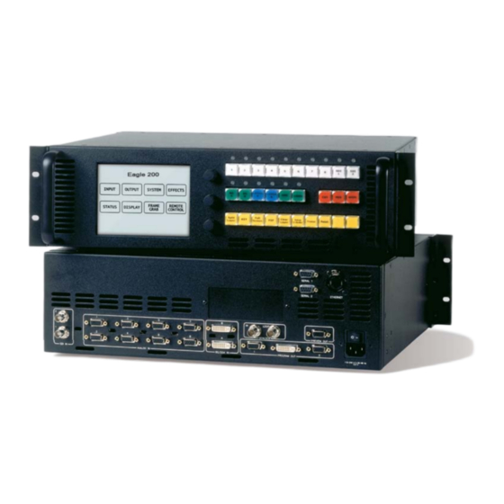
Page 23: Eagle 200 Rear Panel
OK==e~êÇï~êÉ=lêáÉåí~íáçå få=qÜáë=`Ü~éíÉê This chapter provides detailed information about the Eagle 200’s hardware. The following topics are discussed: • Eagle 200 Rear Panel • Eagle 200 Front Panel • Use of Color • Front Panel Sections Eagle 200 • User’s Guide... - Page 24 2. Hardware Orientation Eagle 200 Rear Panel b~ÖäÉ=OMM=oÉ~ê=m~åÉä The figure below illustrates the Eagle 200 rear panel: Figure 2-1. Eagle 200 Rear Panel SDI Inputs Preview Output Serial Ports Analog Inputs AC Connector Ethernet Port Background/DSK Inputs Genlock Connectors Program Outputs Termination Switch Following are descriptions of each rear panel connector and section.
- Page 25 BNC cable from the Genlock Loop connector to the next device’s Genlock In connector. If this Eagle 200 chassis is the last device in a reference video chain, do not make any connections to the Genlock Loop connector.
- Page 26 User feedback for the current switch position is provided on the system’s Genlock Menu . Please note: Use the “ terminated ” setting (75 Ohms) if the Eagle 200 chassis is the last device in a reference video chain. Use the “ high impedance ” setting (Hi-Z) if you are looping reference video to another chassis in your system.
-
Page 27: Touch Screen Menu Section
Source Selection Bus Layer Control Section The Layer Control Section is the operational heart of the Eagle 200, enabling you to assign sources to PIPs and keys on the mixer. Here, you control the overall “look” on Preview and Program. Refer to the “... - Page 28 Mixer Functions Section ” heading on page 24 for details. Eagle 200 Model This section displays the Eagle 200 model, either basic or HD. Eagle 200 HD Eagle 200 Figure 2-2. Eagle 200 Model Labels Eagle 200 • User’s Guide...
- Page 29 2. Hardware Orientation Use of Color rëÉ=çÑ=`çäçê Color plays an important “visual” role with the Eagle 200’s front panel buttons: White buttons are used for sources. Yellow buttons are functions and modes that always apply to the active (blinking) layer.
- Page 30 This section provides detailed descriptions and illustrations of each front panel section. The following topics are discussed: • Touch Screen Menu Section • Source Selection Bus • Layer Control Section • Transition Section • Mixer Functions Section Eagle 200 • User’s Guide...
- Page 31 The Top Knob is generally assigned to navigating fields on the selected menu. For example, turning the knob moves a highlight up and down a list of parameters, allowing you to adjust the highlighted function. This knob also adjusts adjacent parameters. Eagle 200 • User’s Guide...
- Page 32 The two SDI buttons correspond to SDI inputs 1 and 2 on the rear panel. These buttons are only labeled (and active) with the HD model of Eagle 200. Press a button in the section to assign the source to the blinking “mixer” button in the Layer Control Section .
- Page 33 DSK and BG B . Following are descriptions of each button’s function. Important Eagle 200 uses a “lookahead” Preview monitor that fully represents how the Program output will appear next . By selecting combinations of PIPs, keys, backgrounds and the DSK, you are composing a Preview image that will appear on Program —...
- Page 34 LOGO , when you fade the LOGO off — the previous "look" is still there. In Chapter 6, refer to the “ Working with Layers ” section on page 120 for complete instructions on all layer, PIP and key modes. Eagle 200 • User’s Guide...
- Page 35 In Chapter 4, refer to the “ Effects Menu ” section on page 63 for menu details. • In Chapter 6, refer to the “ Working with Transitions ” section on page 135 for operational procedures. Eagle 200 • User’s Guide...
- Page 36 Clear Layer — press Clear Layer to remove the currently selected (blinking) layer from Preview — in preparation for transitioning it off Program. Clear In Chapter 6, refer to the “ Clearing Layers from Program ” section on page 128 for Layer instructions. Eagle 200 • User’s Guide...
- Page 37 Move — press to pend a “move” for a PIP or key, enabling you to fly the PIP or key from one location to another on the next auto transition. Move In Chapter 6, refer to the “ Using Move ” section on page 132 for complete instructions. Eagle 200 • User’s Guide...
- Page 38 2. Hardware Orientation Front Panel Sections Eagle 200 • User’s Guide...
-
Page 39: Safety Precautions
PK==e~êÇï~êÉ=fåëí~ää~íáçå få=qÜáë=`Ü~éíÉê This chapter provides comprehensive installation instructions for the Eagle 200 system’s hardware. The following topics are discussed: • Safety Precautions • Unpacking and Inspection • Site Preparation • Rack-Mount Installation • Cable and Adapter Information • Input Connection Chart •... - Page 40 Before opening the Eagle 200 shipping box, inspect it for damage. If you find any damage, notify the shipping carrier immediately for all claims adjustments. As you open the box, compare its contents against the packing slip. If you find any shortages, contact your sales representative.
- Page 41 3. Hardware Installation Cable and Adapter Information • Rack mount each Eagle 200 chassis from the front rack ears using four rack screws (not supplied). Rack threads may be metric or otherwise — depending upon the rack type. • Install the lower of the two mounting holes first.
- Page 42 Input Connection Chart fåéìí=`çååÉÅíáçå=`Ü~êí= The following Input Connection Chart is provided to assist with your input connections. Please complete one chart for every Eagle 200 system, and make copies as required. Please note the following important points: • The mixer has eight analog input connections (scaled), and with the HD model, two scaled HD/SD inputs.
- Page 43 Analog Input 8 Scaled HD/SD Input 1 (HD model only) Scaled HD/SD Input 2 (HD model only) Scaled BG Input A Digital, Unscaled - BG [ BG/DSK Input B Digital, Unscaled - BG [ ] DSK [ Eagle 200 • User’s Guide...
- Page 44 NOTE: When using an Analog Matrix, the SDI inputs are currently non-functional. Conversely, when using an SDI Matrix, analog inputs are currently non-functional. fåëí~ää~íáçå The figure below illustrates a block diagram of a basic Eagle 200 system. This diagram can be used as reference in the following installation procedure. Program...
-
Page 45: Installation
Power Connection — connect an AC power cord to the AC Power Connector on the rear of the Eagle 200 chassis, and then to AC outlets. Connect AC Power cords (or AC adapters) to all peripheral equipment, such as Ethernet Hubs and monitors. - Page 46 3. Hardware Installation Installation 11. Genlock Termination On the rear of the Eagle 200 chassis, one recessed switch is provided for genlock termination. Note Eagle 200 units are shipped from the factory with the Termination Switch in the “terminated” (75 Ohms) position.
-
Page 47: Home Menu
QK==jÉåì=lêáÉåí~íáçå få=qÜáë=`Ü~éíÉê This chapter describes all Eagle 200 system menus, including how they are accessed, the functions that are available, and simple descriptions of each menu tree (in block diagram format). The following menus are discussed: • Home Menu •... - Page 48 Parameters and values displayed between brackets (e.g., [525] ) cannot be changed. • Press { HOME } to return to the Home Menu . • Press { BACK } to return to the menu from which you accessed the current menu. Eagle 200 • User’s Guide...
-
Page 49: Input Menu
The figure below illustrates the Input Menu tree: Source Selection HOME MENU INPUT Input Acquisition Menu Input Configuration Menu INPUT MENU Aspect Ratio Menu SELECT COLOR FORCE SIZING FORMAT BALANCE ACQUIRE Color Sizing Balance Menu Menu Figure 4-2. Input Menu Tree Eagle 200 • User’s Guide... -
Page 50: Input Configuration Menu
Displays the resolution that is automatically determined by the FORCE ACQUIRE function. Enables you to set the resolution of the incoming source if desired. Once { SELECT the format is selected manually with the rotary knob, press FORMAT } to “accept” the selection. Eagle 200 • User’s Guide... - Page 51 • Input Type — sets the type of input connected to the Eagle 200, such as RGB, SD, HD or Composite. Available choices change depending on the selected Composite/S-Video SDI and HD format.
-
Page 52: Sizing Menu
” section on page 42 for details. fåéìí=mêÉ=~åÇ=pìÄ=jÉåìë The following pre and sub menus can be accessed from the Input Menu : • Input Acquisition Menu • Input Configuration Menu • Sizing Menu • Color Balance Menu • Aspect Ratio Menu Eagle 200 • User’s Guide... - Page 53 With a connection established, press { FORCE ACQUIRE } to perform the optimum image setup and automatically display the Input Menu , or ... • Press { ADJUST } to display the Input Menu without performing a FORCE ACQUIRE. Eagle 200 • User’s Guide...
- Page 54 • Press { SAVE } to save the selected input in the designated input file. • Press { DELETE } to delete the selected input file. Eagle 200 • User’s Guide...
- Page 55 V Total — fixed value which cannot be adjusted. • V Active — sets the number of vertical lines in the image. • V Position — sets the start of the active area’s vertical offset from V sync. Eagle 200 • User’s Guide...
- Page 56 Adjustments can be made on the Oversample Sizing Menu . Note If you switch to another input, the menu does not change. If there is no valid input video, the settings are not applicable. Eagle 200 • User’s Guide...
-
Page 57: Color Balance Menu
Hue does not apply to this type of source. • Press { SAVE } to save the selected input in the designated input file. • Press { RESET ALL } to return all parameters to their default values. Eagle 200 • User’s Guide... -
Page 58: Aspect Ratio Menu
Ratio — when Custom is selected, the Ratio line appears. Enter a custom aspect ratio as desired. The field is hidden when pre-defined ratios are selected. • Press { SAVE } to save the selected input in the designated input file. Eagle 200 • User’s Guide... -
Page 59: Output Menu
The figure below illustrates the Output Menu tree: HOME MENU OUTPUT Genlock Menu OUTPUT MENU SELECT TEST SETTINGS FORMAT PATTERN Test Settings Pattern Menu Menu Figure 4-11. Output Menu Tree All functions and sub menus are discussed in the following sections. Eagle 200 • User’s Guide... -
Page 60: Genlock Menu
SETTINGS FORMAT PATTERN Figure 4-12. Output Menu (sample) The Output Menu enables you to configure Eagle 200’s outputs, including the ability to display test patterns. To access the menu: • Press { OUTPUT } on the Home Menu . Note that brief “help” messages are displayed to assist you with format selection and EDID programming. -
Page 61: Test Pattern Menu
Sync Out — sets the desired sync value. Select +H+V , -H-V , +H-V , -H+V or CSync . • SOG — turns the “sync on green” signal Off or On . • Gamma — sets the output gamma to match that of your projector. The default value is 1.0. Eagle 200 • User’s Guide... - Page 62 Genlock Loop BNC. Figure 4-14. Genlock Menu (sample) The Genlock Menu tells the Eagle 200 which type of analog genlock signal is connected to the Genlock In BNC connector. • Source — sets the genlock source, either Black Burst , CSync or None .
- Page 63 The Burst test pattern is the only pattern that is smaller than the selected output resolution. When the Raster Box is enabled, the Burst pattern will appear within its boundaries. The Raster Box can be enabled when the test pattern is Off . Eagle 200 • User’s Guide...
-
Page 64: System Menu
SERIAL 1 EDID Key Detect Menu SUPPORT Technical Serial 1 Port EDID DVI Support Menu Setup Input Format Menu Menu Figure 4-16. System Menu Tree All functions and sub menus are discussed in the following sections. Eagle 200 • User’s Guide... - Page 65 SAVE SUPPORT Figure 4-17. System Menu (sample) The System Menu enables you to configure Eagle 200 using various functions and sub menus, and set the operation mode for the Split Layer button. To access the menu: • Press { SYSTEM } on the Home Menu .
- Page 66 Press { TECH SUPPORT } to display the Technical Support Menu . Refer to the “ Technical Support Menu ” section on page 62 for details. • Press { SAVE } to save all settings in the system file. Eagle 200 • User’s Guide...
-
Page 67: Diagnostics Setup Menu
Figure 4-18. Diagnostics Setup Menu (sample) The Diagnostics Setup Menu enables you to perform a variety of diagnostic tests on the Eagle 200. The following functions are provided: • Reset Rotary Encoders — (Yes/No) determines whether or not you wish to reset the rotary encoder values when you exit the Rotary Encoder Menu . - Page 68 The Rotary Encoder Menu enables you to test the functionality of each rotary encoder, displaying both relative and absolute counts for each. • Press { EXIT } to return to the Diagnostics Setup Menu . Eagle 200 • User’s Guide...
- Page 69 The Key Detect Menu shows you the key that is pressed, its status (pressed or released) its scan code and its location in the button matrix. • Press { EXIT } to return to the Diagnostics Setup Menu . Eagle 200 • User’s Guide...
- Page 70 Press { YES } to start the reset procedure. An “ In Progress ” message will be displayed. Press { NO } to cancel the procedure. Note A factory reset will erase any “frame grab” images that have been stored in flash memory. Eagle 200 • User’s Guide...
- Page 71 Figure 4-22. Software Version Menu (sample) The Software Version Menu enables you to display and verify the system’s software version. The following functions are provided: • Eagle 200 — displays the system’s current software version. Eagle 200 • User’s Guide...
-
Page 72: Serial 1 Port Setup Menu
NONE Stop Bits Figure 4-23. Serial 1 Port Setup Menu (sample) The Serial 1 Port Setup Menu enables you to set the Eagle 200’s RS-232 communications parameters for serial port 1. • Baud Rate — sets the desired baud rate ( 2400 , 4800 , 9600 , 14400 , 19200 , 28800 , 38400 , 57600 , 115200 ). -
Page 73: Edid Dvi Input Format Menu
The Eagle 200 EDID file is stored in non-volatile memory. This file is read by an external computer’s DVI graphic card when the DVI output is connected to the Eagle 200’s BG A or BG/DSK B input connectors during boot-up. -
Page 74: Technical Support Menu
From the System Menu , press { TECH SUPPORT } to display the Technical Support Menu : TECHNICAL SUPPORT Eagle 200 1.00 Phone: 800-332-3771 Figure 4-25. Technical Support Menu (sample) The Technical Support Menu lists the current version of Eagle 200 software, and displays the Technical Support phone number. Eagle 200 • User’s Guide... -
Page 75: Effects Menu
Key Frame Effect — displays the type of motion used for Move effects. The motion type is currently fixed as LINEAR . Note Eagle 200 can perform wipes in conjunction with both PIPs and Keys. Eagle 200 • User’s Guide... -
Page 76: Status Menu
The Status Menu provides basic software version information, as shown in the sample menu below: SYSTEM STATUS Eagle 200 1.00 Figure 4-27. Status Menu (sample) The following status information is provided: • Eagle 200 — displays the system’s current software version. Eagle 200 • User’s Guide... -
Page 77: Display Settings Menu
Once pressed, you will be prompted to touch the center of a target three times. At the conclusion of the procedure, the display is calibrated and the system returns to the Home Menu . Eagle 200 • User’s Guide... -
Page 78: Keypad Backlight Menu
The following adjustments are provided: • Keypad Backlight — use the top rotary knob to adjust the backlight of all “dim” (un-selected) front panel buttons. This adjustment will assist overall button visibility in dark control room or stage settings. Eagle 200 • User’s Guide... -
Page 79: Pip Adjustment Menu
Crop Menu Pip Adjustment Menu Pip Adjustment Menu Border Menu Border Menu Shadow Menu Input Source Adjustment Menu Figure 4-30. PIP Adjustment Menu Tree All functions and sub menus are discussed in the following sections. Eagle 200 • User’s Guide... -
Page 80: Pip Functions
( 00 ), as measured from the exact center of the PIP. Thus, the value -34 is 34 pixels to the left of center. Use the H Pos knob to move the image left and right along the X-Axis. Eagle 200 • User’s Guide... -
Page 81: Border Menu
(such as Shadow or Border ) will be affected. mfm=^ÇàìëíãÉåí=pìÄ=jÉåìë The following sub menus can be accessed via the PIP Adjustment Menu : • Border Menu • Crop Menu • Shadow Menu • Image Effects Menu • Input Source Adjustment Menu Eagle 200 • User’s Guide... - Page 82 ” section on page 73 for details. Note To remove any border effects from the PIP, press the RESET button in the Layer Functions Section . No other parameters (such as Size or Crop ) will be affected. Eagle 200 • User’s Guide...
- Page 83 Input Source Adjustment Menu ” section on page 81 for details. • Press { BORDER } to display the Border Menu . Refer to the “ Border Menu ” section on page 70 for details. Eagle 200 • User’s Guide...
- Page 84 Enable the { TRACK SIZE } function to adjust the shadow’s H Size and V Size proportionally. • Press { PIP } to return to the PIP Adjustment Menu . Refer to the “ Adjustment Menu Functions ” section on page 68 for details. Eagle 200 • User’s Guide...
-
Page 85: Image Effects Menu
Monochrome Mode is enabled. For a sepia tone effect, turn Monochrome Mode on, and set Red to 100, Green to 65 and Blue to 10. • Invert — enables you to invert all image colors. Eagle 200 • User’s Guide... - Page 86 Shadow Menu ” section on page 72 for details. Note To remove any image effects from the PIP or Key, press the RESET button in the Layer Functions Section . No other parameters will be affected. Eagle 200 • User’s Guide...
-
Page 87: Key Menu
Key Adjustment Matte Menu Menu Key Menu Key Menu Image Effects Menu Matte Menu Key Adjustment Menu Crop Menu Figure 4-36. Key Menu Tree All functions and sub menus are discussed in the following sections. Eagle 200 • User’s Guide... - Page 88 Gain only affects the key hole, as set by the clip. Adjustment range is 0 to 1023.99. • Opacity — enables you to adjust the opacity of the keyed image, from fully opaque to fully transparent. Adjustment range is 0 to 1024. Eagle 200 • User’s Guide...
-
Page 89: Matte Menu
Layer Functions Section . No other parameters will be affected. hÉó=pìÄ=jÉåìë The following sub menus can be accessed from the Key Adjustment Menu : • Crop Menu • Matte Menu • Key Adjustment Menu Eagle 200 • User’s Guide... - Page 90 Press { SIZE & POS } to display the Key Adjustment Menu . Refer to the “ Adjustment Menu ” section on page 79 for details. Note To return all matte values to 512 , press the RESET button in the Layer Functions Section . No other parameters will be affected. Eagle 200 • User’s Guide...
-
Page 91: Key Adjustment Menu
Key Frame Effect — indicates the “motion type” that is used to move the Key from point to point. If no move is programmed, the display reads [N/A] . If a move is programmed, the motion type is fixed as [Linear] . Eagle 200 • User’s Guide... - Page 92 Press { V SIZE } to adjust only the vertical size, leaving the horizontal size as is. In this way, you can stretch the Key vertically. • Press { RATE } to adjust the move rate of the Key, from keyframe to keyframe. Eagle 200 • User’s Guide...
-
Page 93: Input Source Adjustment Menu
Pip Adjustment Menu Shadow Menu Image Effects Menu Crop Menu Pip Adjustment Menu Border Menu Input Source Adjustment Menu Figure 4-40. Input Source Adjustment Menu Tree All functions and sub menus are discussed in the following sections. Eagle 200 • User’s Guide... - Page 94 ( 00 ) with no offset. Thus, the value 50 is 50 pixels to the right of its default position. Use the H Pos knob to move the source left and right along the X-Axis. Eagle 200 • User’s Guide...
- Page 95 Press { V SIZE } to adjust only the vertical size, leaving the horizontal size as is. In this way, you can stretch the input source vertically. • Press { RATE } to adjust the move rate of the PIP or Key, from keyframe to keyframe. Eagle 200 • User’s Guide...
-
Page 96: Background Input Setup Menu
The figure below illustrates the Background Input Setup Menu tree: Home Menu BACKGROUND INPUT SETUP MENU Background Matte Menu FRAME GRAB Frame Grab Menu Figure 4-42. Background Input Setup Menu Tree All functions and sub menus are discussed in the following sections. Eagle 200 • User’s Guide... -
Page 97: Background Input Setup Menu Description
BG A or BG/DSK B input. When MATTE is selected, a solid color can be used as defined on the Background Matte Menu . Refer to the “ Background Matte Menu ” section on page 87 for menu details. Eagle 200 • User’s Guide... - Page 98 Press { FRAME GRAB } to display the Frame Grab Menu . Refer to the “ Frame Grab Menu ” section page 88 on for details. • Press { FORCE ACQUIRE } to automatically detect the input signal resolution and update the display Format field accordingly. Eagle 200 • User’s Guide...
- Page 99 • Press { MAX } to change the highlighted color to 1023 . • Press { BLACK } to change all three colors to 0 . Note The default state is a black matte color. Eagle 200 • User’s Guide...
-
Page 100: Frame Grab Menu
— if one is on program, the other can not be used. The three frame stores utilize Eagle 200’s “temp” (temporary) memory for on-air production. During operation, you can overwrite the memory with new captured stills as desired —... - Page 101 FG to Capture — enables you to select FG_1, FG_2 or FG_3 for capture. • Capture Format — displays the output resolution. Eagle 200 always captures a full screen image at the output resolution — regardless of the input resolution.
-
Page 102: Dsk Adjustment Menu
MENU INPUT MATTE SETUP DSK Input DSK Matte Setup Menu Adjustment Menu Key Adjustment Menu Frame Grab Menu Figure 4-47. DSK Adjustment Menu Tree All functions and sub menus are discussed in the following sections. Eagle 200 • User’s Guide... - Page 103 “ section on page 94 for details. • Press { INPUT SETUP } to display the DSK Input Setup Menu . Refer to the “ Input Setup Menu ” section on page 92 for details. Eagle 200 • User’s Guide...
-
Page 104: Dsk Input Setup Menu
When FG_1, FG_2, or FG_3 is selected, one of the three internal frame stores is the DSK’s input. • Format — this line performs two functions: Displays the resolution that is automatically determined by the FORCE ACQUIRE function. Eagle 200 • User’s Guide... - Page 105 Press { FRAME GRAB } to display the DSK Frame Grab Menu . Refer to the “ Frame Grab Menu ” section page 88 on for details. • Press { FORCE ACQUIRE } to automatically detect the DSK input signal resolution and update the display Format field accordingly. Eagle 200 • User’s Guide...
- Page 106 Press { MIN } to change the highlighted color to 0 . • Press { MAX } to change the highlighted color to 1023 . • Press { BLACK } to change all three colors to 0 . Eagle 200 • User’s Guide...
-
Page 107: Logo Input Setup Menu
In the Temp FG Info section: File Name — displays the selected still frame’s temporary storage register. Resolution — displays the resolution of the selected still frame. • Press { SAVE } to save all LOGO parameters in memory. Eagle 200 • User’s Guide... -
Page 108: Remote Control Menu
• Unit ID — When Eagle 200 is controlled from an Encore or Eagle 200 Controller, this function sets the ID of the Eagle 200 chassis. The ID range is 1 to 32 . Important Encore or Eagle 200 Controllers will detect multiple IDs and prompt the user to correct the problem. - Page 109 • Network server When remote control is off, you can change the Eagle 200 static IP address. When you navigate to the field, the “ ^ “ symbol appears below the first quad, and a { NEXT IP QUAD } button appears: •...
- Page 110 4. Menu Orientation Remote Control Menu Eagle 200 • User’s Guide...
-
Page 111: Setup Prerequisites
RK==póëíÉã=pÉíìé få=qÜáë=`Ü~éíÉê This chapter provides detailed instructions for setting up the Eagle 200 system. It is recommended that you follow all procedures in the order outlined below: • Setup Prerequisites • Return to Factory Default • Touch Screen Calibration •... - Page 112 • When a procedure tells you to “ adjust ” or “ select ” a certain parameter, use the ADJ rotary knob. SRC_3 Preview HD_15 SD YUV SMPTE Figure 5-1. Menu Navigation Eagle 200 • User’s Guide...
- Page 113 • Output raster box On (on Preview). Note The factory reset “defaults” are designed so that initially, your Eagle 200 system is operationally compatible with a previous model. Please continue with the “ Touch Screen Calibration ” section on page 101.
-
Page 114: Output Setup
• Ensure that you know your projector’s native resolution. Refer to your projector’s technical manual for details. Use the following steps to set up the Eagle 200 output. Note The Eagle 200 output format must match your projector’s native resolution. -
Page 115: Quick Input Setup Procedure
Press { ADJUST } to display the Input Menu without performing a FORCE ACQUIRE. To fine tune the input using the Input Menu , refer to the “ Comprehensive Input Setup ” section on page 104 for details. Eagle 200 • User’s Guide... -
Page 116: Comprehensive Input Setup
If required, scroll to the Format line and manually set the resolution of the incoming source. In Appendix A, refer to the “ Input and Output Resolutions “ section on page 149 for details on all available resolutions. Eagle 200 • User’s Guide... - Page 117 If required, press { RESET ALL } to return to default values. Press { SAVE } to save the selected input in the designated file. Press { BACK } to return to the Input Menu . Eagle 200 • User’s Guide...
- Page 118 Note In the current version of Eagle 200, the file number and name (into which you will save data) automatically default to the input number and cannot be changed.
-
Page 119: Setting Up Backgrounds
Setting up Backgrounds pÉííáåÖ=ìé=_~ÅâÖêçìåÇë With Eagle 200, you can use a DVI input, a matte color, or a still frame as a background source. You can also change which source you use during the course of a live production — provided that your backgrounds have been properly set up. Please note: •... - Page 120 Repeat from step 1 if you wish to set up a solid background matte color for the other background source. Please continue with the “ Using a DVI Input as a Background or DSK ” section on page 109. Eagle 200 • User’s Guide...
- Page 121 — both cannot be on-air simultaneously Use the following steps to set up a DVI input as a background or the DSK source: Ensure that the Eagle 200 EDID is properly programmed. Refer to the “...
- Page 122 Setup Menu will appear. Scroll to the Type line and select the desired still frame ( FG_1 , FG_2 and FG_3 ). Please continue with the “ Setting up the DSK ” section on page 111. Eagle 200 • User’s Guide...
-
Page 123: Setting Up The Dsk
Setting up the DSK pÉííáåÖ=ìé=íÜÉ=aph With Eagle 200, you can use a DVI input or a still frame as the DSK source. You can also change which source you use for the DSK during the course of a live production —... - Page 124 Press { INPUT SETUP } to display the DSK Input Setup Menu . Scroll to the Type line and select the desired still frame. Please continue with the “ Setting up the LOGO ” section on page 113. Eagle 200 • User’s Guide...
-
Page 125: Setting Up The Logo
Setting up the LOGO pÉííáåÖ=ìé=íÜÉ=ildl With Eagle 200, you can set the LOGO source as a captured still frame, or leave it as Black (the default value upon factory reset). You can also change which source you use during the course of a live production. - Page 126 5. System Setup Saving the Setup Eagle 200 • User’s Guide...
-
Page 127: Prerequisites
SK==léÉê~íáçåë få=qÜáë=`Ü~éíÉê This chapter includes operational instructions for all Eagle 200 modes and functions. The following topics are discussed: • Prerequisites • Operational Configuration • Lookahead Preview • Working with Layers • Working with Layer Functions • Using Move •... - Page 128 6. Operations Prerequisites mêÉêÉèìáëáíÉë Prior to using the Eagle 200 system, please ensure the following: • All system inputs, backgrounds, the DSK and the LOGO are properly configured. In Chapter 5, refer to the following sections for details: “ Comprehensive Input Setup “...
-
Page 129: Monitor Layout
If required, press { HOME } to display the Home Menu . Press { DISPLAY } to show the Display Settings Menu . Press { LCD CAL } to display the first Touch Screen Calibration Menu . Follow directions on screen to complete the calibration procedure. Eagle 200 • User’s Guide... - Page 130 Operational Configuration iççâ~ÜÉ~Ç=mêÉîáÉï Eagle 200 uses a “lookahead” preview system that ensures the accuracy of all your transitions. The “look” or appearance that you create on your Preview monitor represents the exact appearance of your Program screen — after you cut, mix or wipe the images to program.
- Page 131 6. Operations Operational Configuration råÇÉêëí~åÇáåÖ=o~ëíÉê=_çñÉë With Eagle 200, Raster Boxes are always enabled on Preview, each PIP or Key is surrounded by a thin border that helps you identify the PIP or Key’s original layer. • The PIP or Key with a red “corner” style raster box is Layer A .
-
Page 132: Working With Layers
If you select a layer in the Layer Control Section that is lit (but not blinking), it will blink — and the corresponding “assigned” source on the Source Selection Bus will blink. This method also allows you to quickly verify layer/source selections. Eagle 200 • User’s Guide... - Page 133 The similar situation is true for BG B . • If BG A is on Program and BG B is selected in Preview, BG A will transition to BG B on the next CUT , WIPE or MIX . Eagle 200 • User’s Guide...
-
Page 134: Split Mode
6. Operations Working with Layers råÇÉêëí~åÇáåÖ=péäáí=~åÇ=jáñ=jçÇÉë Eagle 200 provides two different modes with which you can transition PIPs and Keys: • Split Mode • Mix Mode péäáí=jçÇÉ With the Split Layer button lit, the mixer’s two layers operate independently . You can size,... - Page 135 In the Mixer Functions Section , ensure that the PIP button is lit and the PIP Adjustment Menu is visible. If the menu is not visible, press PIP . Note Even if the layer is on Program, the PIP Adjustment Menu appears, but parameters can not be adjusted. Eagle 200 • User’s Guide...
- Page 136 Transition the new "look" to program with a MIX , WIPE or CUT . Refer to the “ Working with Transitions “ section on page 135 for details. Repeat the procedure from step 1 for the next transition. Eagle 200 • User’s Guide...
- Page 137 Press Freeze to freeze the PIP (on both Program and Preview). Press again to unfreeze. Transition — Transition the new "look" to program with a MIX , WIPE or CUT . Refer to the “ Working with Transitions “ section on page 135 for details. Eagle 200 • User’s Guide...
-
Page 138: Working With Pips In Split Mode
Use the following steps to work with Keys in Mix Mode . In the Mixer Functions Section , ensure that the Split Layer button is Off . Press the desired layer button ( A or B ). Please note: Eagle 200 • User’s Guide... -
Page 139: Modifying Keys
Adjustment Menu . Use the menu to adjust the source image’s size and position within the PIP. In Chapter 4, refer to the " Input Source Adjustment Menu Description " section on page 82 for menu details. Eagle 200 • User’s Guide... - Page 140 Prior to the transition, if you want to clear additional layers from Preview, repeat steps 2 and 3 . Transition the new "look" to program with a MIX , WIPE or CUT . The selected layer(s) will transition off of Program. Eagle 200 • User’s Guide...
-
Page 141: Working With Layer Functions
In the Mixer Functions Section , press Swap Z-Order . The visual priority (on Preview) of the two layers changes. Note that the layers remain at their current locations — only the priority changes. Transition the new "look" to program with a MIX , WIPE or CUT . Eagle 200 • User’s Guide... - Page 142 Ensure that Freeze is off. Frozen PIPs or Keys cannot be reset. If required, access the "menu" whose specific function you want to reset (e.g., borders, shadows, special effect, size, etc). In the Mixer Functions Section , press Reset to reset the current effect. Eagle 200 • User’s Guide...
- Page 143 Transition the LOGO to Program with a MIX , WIPE or CUT . A transition to black will occur. Note After a transition, the LOGO layer is automatically cleared from Preview. In this way the next transition will always fade up from black to your previous setup. Eagle 200 • User’s Guide...
-
Page 144: Using Move
• Move Notes mêçÖê~ããáåÖ=jçîÉë Eagle 200 enables you to move a PIP or a key smoothly from one screen location to another at a predefined rate, while the layer is on-air. All moves are two-keyframe effects, Move with a starting location and an ending (destination) location. -
Page 145: Pend On Preview Method
To move the layer back to keyframe 1, press Move . The button lights and on Preview, the raster box blinks at the "starting" location. Perform a MIX , CUT or WIPE . In this "ping-pong" manner, you can continue to transit back and forth between keyframes 1 and 2. Eagle 200 • User’s Guide... - Page 146 — To clear a move (and remove the association between a layer and a move), press Move Setup twice. • On screen, off screen — Eagle 200 enables you to move a PIP or Key from an offscreen location to an onscreen location, and vice-versa. • Switching modes —...
-
Page 147: Working With Transitions
Adjust the Transition Rate field for the desired rate, in 0.1 second increments. Adjust the Transition Wipe field for the desired wipe pattern. Adjust the Transition Edge field for the desired wipe edge. In the Transition Section , press WIPE to wipe the setup to Program. Eagle 200 • User’s Guide... -
Page 148: Modifying Layers On Program
Modifying Layers On Program jçÇáÑóáåÖ=i~óÉêë=lå=mêçÖê~ã The Eagle 200 system enables you to modify layers directly on Program, without first setting up a "look" on Preview. The mode is typically used for creating and viewing a "look" on Program, especially in conjunction with a large screen projector — when the Preview monitor may be too small to realize the desired result. -
Page 149: Capturing Still Frames
Saving Still Frames in Permanent Memory píáää=cê~ãÉ=`~éíìêÉ=lîÉêîáÉï Eagle 200 enables you to capture still frames into the system’s three internal frame stores, using the system’s BG A or BG/DSK B inputs as full screen sources, or using a layer as a full screen source. - Page 150 Captured stills reside in temporary memory. If the system is powered down or reset, the stills will be lost. To save stills in permanent memory, refer to the " Saving Still Frames in Permanent Memory " section on page 139. Eagle 200 • User’s Guide...
-
Page 151: Capturing Still Frames From A Background Input
Press NO to cancel the procedure. If required, press { DELETE } to delete the selected frame from permanent storage. This button only appears when frames are stored in permanent memory. Eagle 200 • User’s Guide... - Page 152 6. Operations Capturing Still Frames Eagle 200 • User’s Guide...
-
Page 153: Input Specifications
^K==péÉÅáÑáÅ~íáçåë få=qÜáë=^ééÉåÇáñ This appendix provides detailed technical specifications for the Eagle 200. The following topics are provided: • Input Specifications • Output Specifications • User Control • Physical and Electrical Specifications • Communications Specifications • Pinouts • Input and Output Resolutions... - Page 154 ^K==péÉÅáÑáÅ~íáçåë Input Specifications fåéìí=péÉÅáÑáÅ~íáçåë= The table below lists Eagle 200 input specifications. Table A-1. Eagle 200 Input Specifications Parameter Specification Scaled Channel Inputs Analog inputs (8) — RGBHV / RGBS / RGsB computer video, YPbPr video (SD or HD), S-video, or composite video on 15-pin HD connector SD and HD-SDI Input (2 optional) —...
- Page 155 HDTV resolutions, progressive up to 1920 x 1080 (1080p) 2048 x 1080p (Digital Cinema format) Plasma display resolutions rëÉê=`çåíêçä= The table below lists Eagle 200 user control specifications. Table A-3. Eagle 200 User Control Specifications Parameter Specification Front Panel control LCD Touch Screen, keyboard circuitry, rotary encoders and LED lighted push buttons.
- Page 156 ^K==péÉÅáÑáÅ~íáçåë Physical and Electrical Specifications mÜóëáÅ~ä=~åÇ=bäÉÅíêáÅ~ä=péÉÅáÑáÅ~íáçåë= The table below lists Eagle 200 physical and electrical specifications. Table A-4. Eagle 200 Physical and Electrical Specifications Parameter Specification Power 120-240 VAC - 50/60 Hz., Auto-selecting 1.0A maximum Mechanical 3 RU Rackmount Chassis H: 5.25 inches (13.34 cm)
-
Page 157: Pinouts
T.M.D.S. Data 0/5 Shield Analog Vertical Sync T.M.D.S. Data 5- T.M.D.S. Data 1- T.M.D.S. Data 5+ T.M.D.S. Data 1+ T.M.D.S. Clock Shield T.M.D.S. Data 1/3 Shield T.M.D.S. Clock + T.M.D.S. Data 3- T.M.D.S. Clock - Eagle 200 • User’s Guide... - Page 158 Table A-8. Analog Input Combinations using Breakout Cable Breakout Cable Composite S-Video Wire Color Video (Y/C) Sync on Green Comp Sync Separate H V (Chrom) (Lum) (Lum) H Sync V Sync Eagle 200 • User’s Guide...
-
Page 159: Ethernet Connector
Table A-9. Ethernet Connector Pinouts Signal Wire Color TX Data + White / Orange TX Data - Orange RX Data + White / Green Blue White / Blue RX Data - Green White / Brown Brown Eagle 200 • User’s Guide... -
Page 160: Serial Connector
The table below lists Serial connector pinouts. Table A-10. Serial Connector Pinouts RS-232 Signal Description Carrier Detect Received Data Transmitted Data Data Terminal Ready Signal Ground Data Set Ready Request To Send Clear To Send Unused Eagle 200 • User’s Guide... -
Page 161: Input And Output Resolutions
Output Menu Description ” sections for details. Note Please contact FSR Technical Support if you would like to request the addition of a new resolution. Input and output resolutions are listed below. Each entry lists Format @Fv (Hz) . Important Eagle 200 does not support interlaced output resolutions. - Page 162 1364x1024 @50 • 1364x1024 @59.94 • 1364x1024 @75 • 1400x1050 @48 • 1400x1050 @50 • 1400x1050 @59.94 • 1400x1050 @60 • 1400x1050 @75 • 1680x1050 @60 • 1600x1200 @47.95 • 1600x1200 @48 • 1600x1200 @50 Eagle 200 • User’s Guide...
- Page 163 1920x1080sF @24 • 1920x1080i @50 (Input Only) • 1920x1080i @59.94 (Input Only) • 1920x1080i @60 (Input Only) • 2048x1080p @50 • 2048x1080p @59.94 • 2048x1080p @60 • 1920x1200p @60 • Apple 1200p @60 • 875p Eagle 200 • User’s Guide...
- Page 164 ^K==péÉÅáÑáÅ~íáçåë Input and Output Resolutions Eagle 200 • User’s Guide...
-
Page 165: In This Appendix
• Contact Information t~êê~åíó Refer to FSR's current price guide for warranty conditions and terms. oÉíìêå=j~íÉêá~ä=^ìíÜçêáò~íáçå=Eoj^F In the unlikely event that a product is required to return for repair, please call the Technical Support / Customer Service direct line, and ask to receive a Return Merchandise Authorization number (RMA). -
Page 166: Contact Information
_K==`çåí~Åí=fåÑçêã~íáçå Contact Information `çåí~Åí=fåÑçêã~íáçå FSR Inc. 244 Bergen Boulevard West Paterson, NJ 07424 • Phone: +1 (800) 332-3771 • Fax: +1 (973) 785-3318 • Website: www.fsrinc.com • Email: sales@fsrinc.com Eagle 200 • User’s Guide... -
Page 167: In This Appendix
`K==réÖê~ÇáåÖ=pçÑíï~êÉ få=qÜáë=^ééÉåÇáñ The following topics are discussed in this Appendix: • Software Upgrade Overview • Serial Upgrade Method • Ethernet Upgrade Method Eagle 200 • User’s Guide... -
Page 168: Software Upgrade Overview
Note Do not move or copy any files out of the target folder. Connect the Serial 1 port on the back of the Eagle 200 to the COM 1 port on your PC. In Chapter 2, refer to the “... - Page 169 Click Communication > RS232 Config > COM Port , and select the COM port on your PC to which the Eagle 200 is connected. If no other programs are using the port, the “ Established communications ” message appears at the bottom of the Flash Loader.
- Page 170 Serial Upgrade Method To verify Eagle 200 communication settings, on the front panel of the Eagle 200 unit press { HOME } > { SYSTEM } > { SERIAL 1 } to display the Serial 1 Port Setup Menu .
-
Page 171: Ethernet Upgrade Method
The factory default IP address for the Eagle 200 system is 192.168.0.10 , so the PC will use 192.168.0.191 as its IP address. Download or obtain the latest Eagle 200 firmware update, and store the file in a designated folder on your PC. - Page 172 Note Do not connect this small network to any other network. Connect the Serial 1 port on the back of the Eagle 200 to the COM 1 port on your PC. In Chapter 2, refer to the “ Eagle 200 Rear Panel ”...
- Page 173 13. Click the Internet Protocol (TCP/IP) line to highlight it, then click the Properties button to display the Internet Protocol (TCP/IP) Properties Dialog . 14. Check the “ Use the following IP address ” check box, as shown below. Figure C-7. Internet Protocol (TCP/IP) Properties Dialog (sample) Eagle 200 • User’s Guide...
- Page 174 In the DOS command window, type ipconfig , and verify that the new IP address is correct. Close the DOS command window. 20. To connect to the Eagle 200 serial port: Click Start > Programs > Accessories > Communications > HyperTerminal to launch the HyperTerminal application.
-
Page 175: Troubleshooting Ethernet Communications
” section on page 165 for instructions. 27. To upload files to the Eagle 200 unit, click the " Open script file to read and upload " button. 28. In the dialog, select " Upload_All.sld " and click Open . The flash loader echoes commands while the flash is being loaded. - Page 176 Press { RESET }. When the confirmation screen appears, press { YES } to reset the system to factory default values. 32. On Eagle 200, verify that the new software has been loaded correctly: From the Home Menu , press { SYSTEM } to access the System Menu .
- Page 177 Use the following steps to determine the IP address of the Eagle 200, and establish proper communications: The default IP address for the Eagle 200 unit is 192.168.0.10. To verify that this is the correct address, open the terminal program and create a serial communication link to the Eagle 200: Click Start >...
- Page 178 Use the unit’s actual IP address, as determined in step 4 above. If the computer is able to successfully communicate with the Eagle 200, you will see a series of “ replies ” from the target IP address. If you see a “ Request timed out ” message, the PC is unable to locate and communicate with the Eagle 200.
-
Page 179: In This Appendix
The following topics are discussed in this Appendix: • Using Remote Control • System Connection • Setting Unique Eagle 200 IDs • Enabling Remote Control • Downloading Code • Destination Setup • Router Setup • Output Patching •... -
Page 180: Using Remote Control
Using Remote Control rëáåÖ=oÉãçíÉ=`çåíêçä When Eagle 200 systems are controlled from an Encore or Eagle 200 Controller as unique destinations, the following procedures must be followed (in the order listed below) to ensure proper communications and control: • System Connection •... - Page 181 A completely “local” network is strongly recommended, without IP connections to the outside world. Repeat step 1 as required for each Eagle 200 chassis that you wish to use as a destination. Using a standard Ethernet cable, connect the Ethernet Port on the rear of the Encore (or Eagle 200) controller to the Hub .
- Page 182 ” section on page 12 for the location of the Ethernet port. Note A completely “local” network is strongly recommended, without IP connections to the outside world. Repeat step 1 as required for each Eagle 200 chassis that you wish to use as a destination. Eagle 200 • User’s Guide...
- Page 183 Using Remote Control Using a standard Ethernet cable, connect the Ethernet Port on the rear of the Encore (or Eagle 200) controller to the Hub . Refer to the “ Encore User’s Guide ” for the location of the controller’s Ethernet port.
- Page 184 ” section on page 12 for the location of the Ethernet port. Note A completely “local” network is strongly recommended, without IP connections to the outside world. Repeat step 1 as required for each Eagle 200 chassis that you wish to use as a destination. Eagle 200 • User’s Guide...
- Page 185 Using Remote Control Using a standard Ethernet cable, connect the Ethernet Port on the rear of the Encore (or Eagle 200) controller to the Hub . Refer to the “ Encore User’s Guide ” for the location of the controller’s Ethernet port.
- Page 186 ” section on page 12 for the location of the Ethernet port. Note A completely “local” network is strongly recommended, without IP connections to the outside world. Repeat step 1 as required for each Eagle 200 chassis that you wish to use as a destination. Eagle 200 • User’s Guide...
-
Page 187: Setting Unique Eagle 200 Ids
Setting Unique Eagle 200 IDs ” section on page 176. pÉííáåÖ=råáèìÉ=b~ÖäÉ=OMM=faë On each Eagle 200 unit, the Remote Control Menu is used to set the Eagle 200 unit ID, and enable/disable remote control itself. Note Ensure that you know the unit IDs that are currently in use by the Encore (or Eagle 200) Controller’s system. -
Page 188: Downloading Code
Use the following steps to enable Eagle 200 remote control: On the Eagle 200 unit, press { HOME } > { REMOTE CONTROL } to access the Remote Control Menu . Scroll to the Remote Control line, and turn it ON . - Page 189 Use the following steps to download code from the Controller to all connected Eagle 200 units: On the Encore or Eagle 200 Controller console, press SYSTEM > { SW VER } to display the Software Version Menu . Press { DOWNLOAD CODE } to begin the download process immediately. The entire process takes several minutes to complete.
-
Page 190: Destination Setup
Scroll to the Type line and select Single Screen SP . Scroll to the SP to Add line and select the Eagle 200 ID that you wish to add. Press { ADD }. (Optional) If you need to remove an ID from a selected destination, scroll to the SP to Remove line and press { REMOVE }. -
Page 191: Router Setup
This procedure is not required if you are using “ Internal ” source routing on your Eagle 200 units. Use the following procedure to set up the routers that are connected to the Eagle 200 units: On the Encore or Eagle 200 Controller console, press SYSTEM > { ROUTER SETUP } to display the Router Specification Menu . - Page 192 10. Repeat the procedure from step 2 to set up each router that is connected to the Eagle 200 units. Please continue with the “ Output Patching ” section on page 181. Eagle 200 • User’s Guide...
-
Page 193: Output Patching
Scroll to the Router Output line and select the specific router output number that you want to patch. Scroll to the SP ID line and select the physical Eagle 200 ID to which the Router’s output is connected. Scroll to the SP Input line and select the physical Eagle 200 input to which the router’s output is connected. -
Page 194: Input Patching
Use the following procedure to set up each router’s input patching. On the Encore or Eagle 200 Controller console, press SYSTEM > { INPUT PATCH } to display the Input Patch Menu , a sample of which is shown below:... -
Page 195: Disabling Remote Control
(internal) router inputs are fed by DAs, select ALL SPs to patch a selected input for all Eagle 200 units simultaneously. For example, if the same VTR feeds input 1 on four Eagle 200 units (via DAs), selecting ALL SPs for the Connection Type saves patching time, and conserves input buttons on the Controller itself. - Page 196 Use the following steps to reestablish local Eagle 200 control: On the Eagle 200 Remote Control Menu , scroll to the Remote Control line turn it OFF . The { HOME } buttons reappears, the Eagle 200 front panel is re-enabled, and all control now originates locally.
- Page 197 {SAVE} ......40, 44 {SELECT FORMAT} ....38, 40, 48 Eagle 200 • User’s Guide...
- Page 198 ......39, 48 button ......22 Eagle 200 • User’s Guide...
- Page 199 ......27 number ......42 Eagle 200 • User’s Guide...
- Page 200 ..79 button ......24 Eagle 200 • User’s Guide...
- Page 201 ....84 DSK adjustment ....90 Eagle 200 • User’s Guide...
- Page 202 Keys in split mode ....126 modify PIPs ..... .125 Eagle 200 • User’s Guide...
- Page 203 Ethernet ....172 external serial .....170 Eagle 200 • User’s Guide...
- Page 204 DSK ....112 system ......99 Eagle 200 • User’s Guide...
- Page 205 ID .......96 IP .......97 Eagle 200 • User’s Guide...
- Page 206 Index Eagle 200 • User’s Guide...
Need help?
Do you have a question about the Eagle 200 and is the answer not in the manual?
Questions and answers