
Subscribe to Our Youtube Channel
Related Manuals for FSR MAS-6100


Summary of Contents for FSR MAS-6100
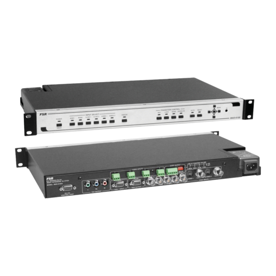
- Page 1 MAS-6100 MAS-6100A Video Products Group AV SWITCHER SCALERS INSTALLATION AND OPERATING GUIDE BASED ON FIRMWARE REV. 1.85 43930 LIT1245 D6...
-
Page 2: Compliance And Safety
COMPLIANCE AND SAFETY PROPRIETARY INFORMATION All information in this manual is proprietary to and the property of FSR Inc. This publication is protected by the Federal Copyright Law, with all rights reserved. No part of this document may be reproduced, transcribed, or transmitted, in any form or by any means, without prior explicit written permission from FSR Inc. -
Page 3: Table Of Contents
IR REMOTE CONTROL COMMANDS ..................32 PINOUTS AND CABLING ....................... 33 HD15 CONNECTOR .............................33 4 PIN MINI-DIN S-VIDEO CONNECTOR (YC) INPUT ..................33 AUDIO WIRING ..............................34 DB9 CONNECTOR ...............................35 MAS-6100 RS232 CONTROL SPECIFICATION ................37 COMMUNICATION PROTOCOL BASICS ......................37 MAS-6100 / MAS-6100A... - Page 4 PACKET FORMAT ..................................38 FRONT PANEL BUTTON EXAMPLES ..........................39 FUNCTION LIST ..................................45 SPECIFICATIONS ..............................51 WARRANTY AND RETURN INFO ........................52 WARRANTY POLICY ................................52 SERVICE AND RETURN AUTHORIZATION .........................52 CONTACT INFORMATION ..............................52 MAS-6100 / MAS-6100A...
-
Page 5: Introduction
RS-232 port or the IR Port. To make IR control easy and painless, all IR codes are provided in a CCF format and are available on the FSR web site. These can be used in nearly any universal remote control or from any control system with IR output. -
Page 6: Installation
INSTALLATION The MAS-6100 mounts easily into a standard 19” rack. It should be placed in an area where the user can easily access the front panel controls. The units are designed to be rack mounted and are supplied with front rack- mount hardware. -
Page 7: Mechanical Dimensions
MECHANICAL DIMENSIONS MAS-6100 / MAS-6100A... -
Page 8: Front And Rear Panel Operation
FRONT PANEL CONTROLS POWER ON OFF Pressing the power button will power up the MAS-6100. The unit will run a brief diagnostic sequence and be operational in a few seconds. Pressing and holding the power button for two seconds and releasing will power down the unit. -
Page 9: Special Button Combinations And Their Functions
The silk-screening lists the various time delay settings in milliseconds. The dip switch values are 85ms, 43ms, 21ms, and 11ms. When a switch is moved to the “UP” position the delay is added to the audio. MAS-6100 / MAS-6100A... -
Page 10: Accessing And Using The On Screen Menus
The ARROW LEFT button is used to move backward or decrement a value. Here are the nine root menu main group headings in the order they appear: • MODEL DISPLAY (FSR MAS-6100) • VIEW THE VERSION NUMBER •... -
Page 11: Mas-6100 Menu Tree
MAS-6100 / MAS-6100A... -
Page 12: The Root Menu Structure
The output video will be locked to the selected source, the syncs will be locked (but with an additional internal video processing Lock & Mix delay) and the background for the output will be that of the Lock source (unless foreground and background are swapped). MAS-6100 / MAS-6100A... - Page 13 Output Adjust Output Adjust Back Y/U/V Back Y/U/V [ 16] [128] [128] [ 16] [128] [128] Sets the value of the fi xed background color, which is present when Dissolve is used with no Lock source background displayed. MAS-6100 / MAS-6100A...
-
Page 14: Scaler Adjust Group
Most resolutions are 4:3 ratio, thus the third number will be 1.333 (4 divided by 3). Another common aspect ratio is 16:9 (16 divided by 9 = 1.777). PAL and NTSC inputs are physically 4:3 on your video monitor, but their actual pixel/line ratios are different and so will not display as 1.333. MAS-6100 / MAS-6100A... - Page 15 Adjustment is provided for a reduction down to 10% of the overall output size. In most cases, this feature is used for picture-in-picture (PIP) when a background image is being used (for units with overlay abilities). MAS-6100 / MAS-6100A...
- Page 16 When left as “Simple”, the H/V components of Zoom and Shrink are adjusted equally i.e. H is equal to V. MAS-6100 / MAS-6100A...
-
Page 17: Key Adjust Group
You will see that the Swap between foreground and background has no effect on the output resolution as this is always set by the Lock source. Note that this is different than simply swapping the input and lock sources as that would affect the fi nal output MAS-6100 / MAS-6100A... - Page 18 (A/D conversion) may not sample a 50% brightness as being exactly 50% i.e. sometimes 49% and sometimes 51%. Increasing the softness value will broaden the range of keyed colors so that the keying of images varies depending on how close a color is to the keyed-out range. MAS-6100 / MAS-6100A...
- Page 19 The descriptions above behave identically on the remaining U Key Invert & V Key Invert component versions. However they are directed at the U/B-Y (blue) color component and V/R-Y (red) color components respectively. Adjustment and effects are the same as explained above for Y Key Invert (brightness/grey-scale). MAS-6100 / MAS-6100A...
-
Page 20: Common Keyer Operations
‘min’ values and increase the ‘max’ values to broaden the range of colors keyed out. At this point, only the key color should remain transparent. MAS-6100 / MAS-6100A... -
Page 21: Input Adjust Group
These settings are often used to correct the position of a PC signal on an input, or to eliminate any undesired noise at the top or bottom of a PAL or NTSC video input. MAS-6100 / MAS-6100A... - Page 22 The Input pixel phase adjustment allows you to change the position (from 0 to 31) where the pixels are sampled, relative to the horizontal sync signal. MAS-6100 / MAS-6100A...
- Page 23 fi elds are simply combined together. The most common artifact is a blurring at the point of maximum movement within an image. Your unit provides some tools to minimize the effects of de-interlacing of an image MAS-6100 / MAS-6100A...
-
Page 24: Cv & Yc Input Sub Menu Items
RGB signals only. The rest of the Input menu items function with RGB, CV or YC type signals. In addition, there are four additional Menu items that are only used with CV or YC type signals and these are explained below: MAS-6100 / MAS-6100A... -
Page 25: Transition Adjust Group
The sub menus will vary depending on which transition is selected as described below. Adjust Transition Adjust Transition Transition Transition [CUT FADE WIPE] [CUT FADE WIPE] Select one of the three transition types. This becomes the current transition when a source is selected. The default is the FADE transition. MAS-6100 / MAS-6100A... -
Page 26: Cut And Fade Sub Menu Items
Adjust Transition Adjust Transition Wipe Size Wipe Size 10-2000] 10-2000] This setting adjusts the thickness of the transition bars. The lower settings will yield a tighter bar pattern with many bars. Higher settings will produce wider bars. MAS-6100 / MAS-6100A... -
Page 27: Adjust Resolutions Group
800 x 600 60 Hz 800 x 600 60 Hz Interlaced Interlaced Off] Off] This adjustment specifi es whether the image is interlaced or progressive scan. It toggles simply On or Off, so there are no fl ashing brackets. MAS-6100 / MAS-6100A... - Page 28 600 lines visible vertically. This item provides a way to change the number of active pixels and lines. 800 x 600 60 Hz 800 x 600 60 Hz H/V Start H/V Start [ 88] x [ 88] x MAS-6100 / MAS-6100A...
- Page 29 Sync can be either negative polarity or positive polarity. To further complicate things, it is possible that you may want to make the Horizontal Sync polarity different from the Vertical Polarity. This control allows you to make that change. There are four possible selections: +H+V -H+V +H-V -H-V MAS-6100 / MAS-6100A...
-
Page 30: System Settings Group
System Settings System Settings FSR version # xxx FSR version # xxx This screen is an informational screen. Should you require technical assistance with your unit, the technical support personnel may request that you read the contents of this screen to them during the support call. - Page 31 No action is taken regardless of the value shown here, however some users have an equipment cleaning or specifi cation audit procedure and this information may be useful to those users. System Settings System Settings Firmware updates Firmware updates MAS-6100 / MAS-6100A...
-
Page 32: Ir Remote Control Commands
AMX and Crestron Control systems. A pre-made template for FSR Room Navigator control of the MAS-6100 is also available on the FSR website along with serial commands. The IR receiver port is located to the far right of the MAS-6100 front panel and is labeled “IR”. MAS-6100 / MAS-6100A... -
Page 33: Pinouts And Cabling
13.H sync (or composite sync for RGBS) 14.V sync 15.SCL (input & output linked) 4 PIN MINI-DIN S-VIDEO CONNECTOR (YC) INPUT Cable Type: Standard 4 pin S-Video to two BNC male cable. Maximum Recommended Length: 35 ft MAS-6100 / MAS-6100A... -
Page 34: Audio Wiring
MAS-6200 AUDIO OUTPUT CONNECTOR WIRING TO A STEREO UNBALANCED TO A MONO UNBALANCED PREAMP INPUT PREAMP INPUT SIGNAL SIGNAL FLOW FLOW TO A STEREO BALANCED TO A MONO BALANCED PREAMP INPUT PREAMP INPUT SIGNAL SIGNAL FLOW FLOW MAS-6100 / MAS-6100A... -
Page 35: Db9 Connector
DB9 CONNECTOR Please see the MAS-6100 serial protocol manual included with the product for serial commands and other details on RS-232 control. RS232 / D9 socket 1.N/C 2.TX (Transmit data) 3.RX (Receive data) 4.N/C 5.GND (Signal return) 6.N/C 7.CTS (Clear to send) 8.RTS (Request to send) - Page 36 MAS-6100 / MAS-6100A...
-
Page 37: Mas-6100 Rs232 Control Specification
MAS-6100 RS232 CONTROL SPECIFICATION This section outlines how to control a unit via RS232 using ASCII-based commands. It details how to send and receive serial data to perform many of the functions that a user has access to on the unit. -
Page 38: Packet Format
Carriage Returns Each packet that is sent to or received from the MAS-6100 is terminated with a carriage return. Carriage return has a value of 13 decimal, but is sent as a hex byte 0x0D. It will be represented in this document as <CR>. -
Page 39: Front Panel Button Examples
<CR> FRONT PANEL BUTTON EXAMPLES If the user is using the serial commands to simulate the front panel of the MAS-6100, the following commands are provided. They have been tested. The commands are to be sent out in the following manner, with no spaces between the fi elds. - Page 40 ??, test checksum Source = S-VID1 000040 <CR> Where: 04, Write command 41, Window “A” 00, Output 1 82, Change Program source 000040, Source S-VID1 ??, test checksum Source = S-VID2 000041 <CR> Where: 04, Write command MAS-6100 / MAS-6100A...
- Page 41 41, Window “A” 00, Output 1 82, Change Program source 000031, Source S-VID2 ??, test checksum FREEZE ON 000001 <CR> Where: 04, Write command 41, Window “A” 00, Output 1 9C, Freeze 000001, On ??, test checksum MAS-6100 / MAS-6100A...
- Page 42 000000 <CR> Where: 04, Write command 41, Window “A” 00, Output 1, Key Enable high bit (function is 127) 27, Key 000000, Off ??, test checksum LOCK ON 000001 <CR> Where: 04, Write command 41, Window “A” MAS-6100 / MAS-6100A...
- Page 43 000002, Background on (Lock & Mix) ??, test checksum AUTO 000001 <CR> Where: 04, Write command 41, Window “A” 00, Output 1, FE, Start Autoset function 000002, Background on (Lock & Mix) ??, test checksum DISSOLVE (Transition Type) MAS-6100 / MAS-6100A...
- Page 44 000002, Set transition type to wipe. ??, test checksum Left to Right Wipe (Transition Type) 000000 <CR> Where: 04, Write command 41, Window “A” 01, Output 1, Set wipe type high bit (function is 145). 45, Set transition type. MAS-6100 / MAS-6100A...
-
Page 45: Function List
0 = Off, 1 = On 0 = RGBHV Output image type analogue 2 = RGsB 3 = YUV 0 = RGBHV Output image type digital 3 = YUV 9 = Not available Background Y 16..235 Background U 16..240 Background V 16..240 MAS-6100 / MAS-6100A... - Page 46 0..100 = Fade level % Fade out / in -1= Fade out, 1= Fade in Layer priority 0..5 = Layer priority Headphone volume -16..15 (-16=Mute) Adjust keyers (on certain models only) Keyer enable 0.. 1 = Off, On MAS-6100 / MAS-6100A...
- Page 47 RGB contr. (red) 10..1F 75..150 RGB contr. (green) 10..1F 75..150 RGB contr. (blue) 10..1F 75..150 0..5 = Normal, Auto, Film 3:2, M.comp.low, M.comp. De-int. 10..FF med., M.comp.high (Film mode detected) 10..FF 0..1 = Not detected, Detected Bright 30..5F 0..180 MAS-6100 / MAS-6100A...
- Page 48 Set to 1 to store Buzzer 0..1 = Off, On Power cycles Read only Firmware updates Read only Hours in use Read only Resolutions Read only Number of Testcards Read only Number of logos Read only Board temp. (deg.C) Read only MAS-6100 / MAS-6100A...
- Page 49 TAC number 1 Read only TAC number 2 Read only TAC number 3 Read only TAC number 4 Read only TAC number 5 Read only Not part of menu system Front panel lock 0 = unlocked, 1 = locked MAS-6100 / MAS-6100A...
- Page 50 MAS-6100 / MAS-6100A...
-
Page 51: Specifications
SPECIFICATIONS VIDEO INPUT MODEL MAS-6100 AND MAS-6100A SIGNAL TYPE COMPONENT COMPOSITE S-VIDEO CONNECTOR TWO (VIA OP- ONE 1 BNC FE- ONE HD-15 FE- TWO 4 PIN NUMBER/TYPE TIONAL BREAK- MALE MALE FEMALE DIN OUT) TO HD-15 OR ONE 5-BNC FE-... -
Page 52: Warranty And Return Info
This product is warranted against failures due to defective parts or faulty workmanship for a period of three years after delivery to the original owner. During this period, FSR will make any necessary repairs or replace the unit without charge for parts or labor. Shipping charges to the factory or repair station must be prepaid by the owner, return-shipping charges, via UPS / FedEx ground, will be paid by FSR. - Page 53 MAS-6200...
- Page 54 MAS-6200...
Need help?
Do you have a question about the MAS-6100 and is the answer not in the manual?
Questions and answers