Table of Contents
Advertisement
Quick Links
Advertisement
Table of Contents

Related Manuals for FSR Compass Plus CP-100


Summary of Contents for FSR Compass Plus CP-100
- Page 1 CP-100 rëÉêÛë=dìáÇÉ 43926 LIT1228B...
- Page 2 30 days after the transfer of risks. In the event of justified notice of compliant, FSR can repair the fault or provide a replacement at its own discretion within an appropriate period. If this measure proves to be impossible or unsuccessful, the purchaser can demand a reduction in the purchase price or cancellation of the contract.
- Page 3 Not included in the guarantee coverage are system failures which are attributed to programs or special electronic circuitry provided by the purchaser, e.g. interfaces. Normal wear as well as normal maintenance are not subject to the guarantee provided by FSR either.
- Page 4 léÉê~íçêë=p~ÑÉíó=pìãã~êó The general safety information in this summary is for operating personnel. aç=kçí=oÉãçîÉ=`çîÉêë=çê=m~åÉäë There are no user-serviceable parts within the unit. Removal of the top cover will expose dangerous voltages. To avoid personal injury, do not remove the top cover. Do not operate the unit without the cover installed.
- Page 5 bèìáéãÉåí=j~êâáåÖ=~åÇ=p~ÑÉíó=qÉêãë= t^okfkd Highlights an operating procedure, practice, condition, statement, etc., which, if not strictly observed, could result in injury to or death of personnel. Note Highlights an essential operating procedure, condition or statement. `^rqflk The exclamation point within an equilateral triangle is intended to alert the user to the presence of important operating and maintenance (servicing) instructions in the literature accompanying the appliance.
- Page 6 `Ü~åÖÉ=eáëíçêó The table below lists the changes to the CP-100 User’s Guide. Table 0-1. Change History Date Description Approved By 12/19/07 CP-100 User’s Guide R. Pellicano 6/2/08 CP-100 User’s Guide Revisions: R. Pellicano • Addition of File Association • Addition of Executive Lockout Mode •...
-
Page 7: Table Of Contents
q~ÄäÉ=çÑ=`çåíÉåíë `Ü~éíÉê=N fåíêçÇìÅíáçå =K=K=K=K=K=K=K=K=K=K=K=K=K=K=K=K=K=K=K=K=K=K=K=K=K=K=K=K=K=K=K=K=K=K=K=K=K=K=K=K=K=NP In This Chapter ..........13 Chapter Structure . - Page 8 Table of Contents Button States ..........37 Quick Setup and Operations .
- Page 9 Table of Contents Using Inputs ..........82 Input Selection Rules .
- Page 10 Table of Contents Communications Specifications ........113 Agency Specifications .
- Page 11 Table of Contents IHPOS ......... 137 IHTOTAL .
- Page 12 Table of Contents VFDBRT ........150 Key Commands .
-
Page 13: Chapter Structure
NK==fåíêçÇìÅíáçå få=qÜáë=`Ü~éíÉê This chapter is designed to introduce you to the CP-100 User’s Guide. Areas to be covered are: • Chapter Structure • How to Use This Guide • Conventions • About the CP-100 • Connectivity Diagram • Application Questions `Ü~éíÉê=píêìÅíìêÉ... - Page 14 NK==fåíêçÇìÅíáçå How to Use This Guide eçï=íç=rëÉ=qÜáë=dìáÇÉ This section provides important tips for streamlining your use of this User’s Guide in its electronic “PDF” form. k~îáÖ~íáåÖ Use Acrobat Reader’s “bookmarks” to navigate to the desired location. All chapter files have the same bookmark structure for instant navigation to any section. Please note: •...
-
Page 15: Overview
NK==fåíêçÇìÅíáçå About the CP-100 ^Äçìí=íÜÉ=`mJNMM The following topics are discussed in this section: • Overview • Features • A Word About HDCP lîÉêîáÉï CP-100 is a high-quality presentation switcher designed to provide true seamless switching between various input sources. High image scaling quality is maintained throughout. CP- 100 offers straightforward and simple operating modes, and is ideal for use in live events, company boardrooms, hotel ballrooms, houses of worship, and in education and training facilities. - Page 16 NK==fåíêçÇìÅíáçå About the CP-100 functions are disabled when the CP-100 processes HDCP content. Refer to the “A Word About HDCP” section on page 18 for more details. 1080i RGB input is supported on the DVI digital input. • The following scaling and de-interlacing features are provided: 10-bit scaling 10-bit 4:2:2 de-interlacer with diagonal filter 165MHz maximum pixel rate...
- Page 17 NK==fåíêçÇìÅíáçå About the CP-100 File Association Menu The System Menu now includes a File Association option that lets you associate one or more configuration files to each of the nine inputs (1 through 8 and SDI), change or recall a configuration file for an input, and delete configuration files.
- Page 18 NK==fåíêçÇìÅíáçå About the CP-100 ^=tçêÇ=^Äçìí=ea`m HDCP stands for High-Bandwidth Digital Content Protection, an industry-wide copy protection scheme that is used to prevent the potential interception of digital data between the source (e.g., a Blu-Ray player) and the target display (e.g., an HDCP compliant display ®...
-
Page 19: Connectivity Diagram
Section” heading on page 24 for details on all inputs. ^ééäáÅ~íáçå=nìÉëíáçåë At FSR, we take pride in offering unique solutions to demanding technical problems. If you have application questions, require further information or would like to discuss your application requirements in more detail, please call +1 (800) 332-3771. Our Customer Support Engineers will be happy to supply you with the support you need. -
Page 20: Application Questions
NK==fåíêçÇìÅíáçå Application Questions CP-100 • User’s Guide... - Page 21 OK==e~êÇï~êÉ=lêáÉåí~íáçå få=qÜáë=`Ü~éíÉê This chapter provides detailed diagrams of the CP-100’s front and rear panels, along with comprehensive explanations of each. The following topics are discussed: • CP-100 Front Panel • CP-100 Rear Panel CP-100 • User’s Guide...
-
Page 22: Display Section
2. Hardware Orientation CP-100 Front Panel `mJNMM=cêçåí=m~åÉä The figure below illustrates the CP-100 front panel: Inputs CP-100 PROGRAM: LOGO 1024x768 @59.94 NEXT: NTSC (480i) Adjust Effects BLACK TAKE Figure 2-1. CP-100 Front Panel Display Section Effects Section Inputs Section Take Button Following are descriptions of each front panel section: Display Section The Display Section includes a four-line display, the ADJUST knob and two... - Page 23 2. Hardware Orientation CP-100 Front Panel aáëéä~ó=pÉÅíáçå The figure below illustrates the Display Section: PROGRAM: 1024x768 @59.94 NEXT: NTSC (480i) Adjust Figure 2-2. Display Section with sample Status Menu Descriptions of each button and control are provided below: • The Menu Display is a 4 line x 20 character Vacuum Fluorescent Display (VFD) that shows all CP-100 menus and sub-menus.
- Page 24 2. Hardware Orientation CP-100 Front Panel • ESC — press to exit a menu without making changes, cancel an operation, to answer “No” to certain menu queries, and to return to the top Status Menu. Each press takes you back up the menu tree by one level. fåéìíë=pÉÅíáçå...
- Page 25 2. Hardware Orientation CP-100 Front Panel • The SDI button selects the SD-SDI or HD-SDI input source. • The LOGO button selects the stored “full screen” logo image for the next transition. If no image is stored, the transition will be to Black. Use the menu to LOGO select one of three stored logos for use.
-
Page 26: Take
2. Hardware Orientation CP-100 Front Panel If “Black Auto Take” is On: • Press BLACK to immediately transition to/from black. – If the transition is “to” black, the button blinks fast during the transition, then lights solid when black is on Program. -
Page 27: Cp-100 Rear Panel
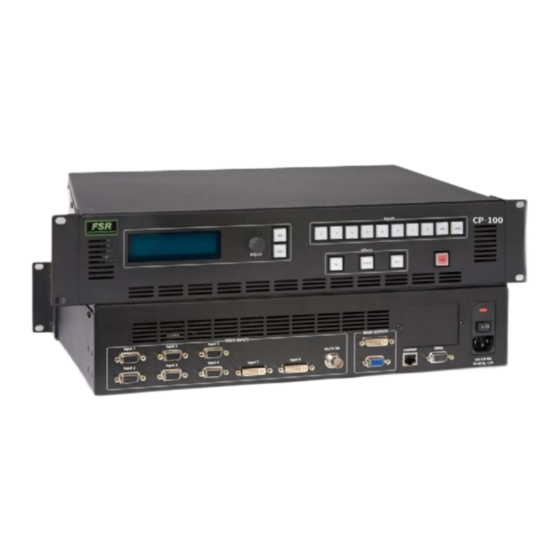
2. Hardware Orientation CP-100 Rear Panel `mJNMM=oÉ~ê=m~åÉä The figure below illustrates the CP-100 rear panel: Model CP-100 100 - 240 VAC 50 – 60 Hz, 1.9A VIDEO INPUTS MAIN OUTPUTS Input 1 Input 3 Input 5 HD/SD SDI SERIAL ETHERNET Input 2 Input 4 Input 6... - Page 28 2. Hardware Orientation CP-100 Rear Panel HD/SD SDI Input One BNC connector is provided for the SD-SDI or HD-SDI input. Main Outputs Two connectors are provided for the CP-100’s main program outputs. Both outputs have the same resolution, and both can be used simultaneously. One DVI-I connector is provided for the system’s digital program output.
-
Page 29: Safety Precautions
PK==fåëí~ää~íáçå få=qÜáë=`Ü~éíÉê This chapter provides detailed instructions for installing the CP-100 hardware. The following topics are discussed: • Safety Precautions • Unpacking and Inspection • Site Preparation • Cable and Adapter Information • Rack-Mount Installation • Power Installation • Signal Installation •... - Page 30 As you open the box, compare its contents against the packing slip. If you find any shortages, contact your FSR sales representative. Once you have removed all the components from their packaging and checked that all the listed components are present, visually inspect each unit to ensure there was no damage during shipping.
- Page 31 3. Installation Rack-Mount Installation o~ÅâJjçìåí=fåëí~ää~íáçå CP-100 units are designed to be rack mounted and are supplied with front rack-mount hardware. Please note the following important points: • When rack mounting the unit, remember that the maximum ambient operating temperature for the unit is 40 degrees C. •...
-
Page 32: Power Installation
3. Installation Power Installation mçïÉê=`çêÇLiáåÉ=sçäí~ÖÉ=pÉäÉÅíáçå CP-100 is rated to operate with the following specifications: • Input Power: 100-240 VAC, 50-60 Hz • Power Consumption: 240 watts maximum CP-100 performs line voltage selection automatically, and no user controls are required. The AC power cords must be accessible so that they can be removed during field servicing. Warning When the CP-100 is used in the 230-volt mode, a UL listed line cord rated for 250 volts at 15 amps must be used and... -
Page 33: Signal Installation
3. Installation Signal Installation páÖå~ä=fåëí~ää~íáçå The figure below illustrates a sample CP-100 system. Use this figure for reference during the signal installation process. Sample Source Input Devices CP-100 Inputs 1 - 6 (Analog) Inputs 7 - 8 (DVI) Analog Input 9 (HD/SD SDI) Ethernet Serial Figure 3-2. -
Page 34: Format Connection Table
3. Installation Format Connection Table GUI connection — to configure your system to run from the built-in web-based GUI, perform the following steps: ® Ensure that your PC (or laptop) uses Windows 2000 or XP. Ensure that your PC (or laptop) has a web browser installed, such as ®... -
Page 35: Control Overview
QK==léÉê~íáçå få=qÜáë=`Ü~éíÉê This chapter provides comprehensive menu descriptions and detailed operating instructions for the CP-100. The following topics are discussed: • Control Overview • Power-Up Initialization • Button States • Quick Setup and Operations • Menu Tree • Using the Menu System •... - Page 36 4. Operation Control Overview `çåíêçä=lîÉêîáÉï There are several ways to control the CP-100: • The front panel is ideal for all basic operations. Available controls include the Display Section and the buttons in the Inputs Section and the Effects Section. •...
- Page 37 4. Operation Button States CP-100 F SR Ve rsion 1. 03 Initializing ... Figure 4-4. System initialization message 4 The “version” line in the above menu shows the software version that is currently installed. This version number changes as software upgrades are released. When you first start up a CP-100 that has stored logos, a message like the one in the following illustration appears during initialization: LOGO1 loading.
- Page 38 4. Operation Quick Setup and Operations nìáÅâ=pÉíìé=~åÇ=léÉê~íáçåë For the optimum speed in setting up and operating your system, use the following steps. For reference, links are provided to the appropriate sections in this guide. Connect power — Ensure that power is properly connected to the CP-100. (Chapter 3, “Power Installation,”...
- Page 39 4. Operation Quick Setup and Operations 17. Ready to roll — With all output, input and system configurations saved, press the desired input button, and press TAKE. Note For advanced system operations, specific system “tweaks” and operating descriptions on every feature, please start with “Quick Function Reference”...
-
Page 40: Menu Tree
4. Operation Menu Tree jÉåì=qêÉÉ The figure below illustrates the entire CP-100 menu tree. Please use this diagram for reference as you learn how to operate the system. Status Menu Setup Menu Trans Time Input System Tech Support Output Key Setup LOGO Setup User Preference Output Format... -
Page 41: Using The Menu System
4. Operation Using the Menu System rëáåÖ=íÜÉ=jÉåì=póëíÉã This section lists the rules and conventions for using CP-100’s menu system. For reference, the figure below illustrates the Setup Menu: SE TUP ME NU > T r a ns T i m e Output >>... - Page 42 4. Operation Using the Menu System • The SEL button is also used to answer “Yes” to certain menu queries. The ESC button is also used to answer “No” to certain menu queries. Note The display itself is four lines high, and the ADJUST knob is used to scroll through the various lines.
-
Page 43: Quick Function Reference
4. Operation Quick Function Reference nìáÅâ=cìåÅíáçå=oÉÑÉêÉåÅÉ Use the following table to quickly access the proper section for a specific function. Both hyperlinks and page numbers are provided. Table 4-1. CP-100 Quick Function Reference Table How to: Use the Following Section: Page Adjust background color Background... - Page 44 4. Operation Quick Function Reference Table 4-1. CP-100 Quick Function Reference Table (Continued) How to: Use the Following Section: Page Save system state Save System State Select inputs Input Selection Rules Set Auto Input Config mode Auto Input Config Set Auto Input Save mode Auto Input Save Set Auto Take mode Auto Take...
-
Page 45: Using The Setup Menu
4. Operation Quick Function Reference Table 4-1. CP-100 Quick Function Reference Table (Continued) How to: Use the Following Section: Page Use the menu system Using the Menu System Use the Output Menu Output Menu Use the Setup Menu Using the Setup Menu Use the Status Menu Status Menu Use the System Menu... - Page 46 4. Operation Status Menu pí~íìë=jÉåì The Status Menu is the system’s top level display, which appears by default after the CP-100 boots up. • To return to the Status Menu from any point within the Setup Menu, press ESC repeatedly. •...
- Page 47 4. Operation Status Menu • Next Input Type — indicates the next input type on Program, and (if applicable), the system’s HDCP status. The following labels can appear, depending on the output and HDCP implementation: HDCP HDCP Violation Important If the label “HDCP Violation” appears, an HDCP source is selected, but a non-HDCP compliant device (e.g., an HDCP repeater) has been detected.
-
Page 48: Trans Time
4. Operation Using the Setup Menu rëáåÖ=íÜÉ=pÉíìé=jÉåì After CP-100 initialization is complete, the Status Menu appears. This is the system’s top- level menu. Refer to the “Status Menu” section on page 46 for details. To display the Setup Menu from the Status Menu, press SEL. Note When you make changes to input, output and system parameters, your “configuration”... -
Page 49: Test Pattern
4. Operation Using the Setup Menu qê~åë=qáãÉ From the Setup Menu, select Trans Time to change the current transition rate that is used when you mix between inputs, when you transition to or from keys, and when you transition to or from black. Following are two illustrations of the transition interval: •... -
Page 50: Save Output Config
4. Operation Using the Setup Menu Following are descriptions of each Output Menu function: • Output Format • Test Pattern • Sync Setup • Gamma • Save Output Config lìíéìí=cçêã~í From the Output Menu, select the top Output Format line to view or change the current output format. - Page 51 4. Operation Using the Setup Menu • Raster Box — This function enables or disables the raster box on the output. When turned ON, the system displays a one-pixel border around the active output area. Note that the raster box includes gaps that enable you to precisely align the input video to fill the output raster.
-
Page 52: Input Menu
4. Operation Using the Setup Menu Please note the following important points regarding the output configuration file: • When you perform the Save Config function, all configuration parameters from the Output Menu are saved in non-volatile memory. If you do not perform the function, output data will not be restored upon the next system power up. -
Page 53: Input Format
4. Operation Using the Setup Menu The Input Menu can be used in two ways: • Press an input button first, TAKE the input to Program, then use the menu to set input parameters. • While you are already in the Input Menu, press a different input button and TAKE it to Program. - Page 54 4. Operation Using the Setup Menu • If the video format is a “best guess” as determined by the “auto acquire” mode, it is displayed (only in the Status Menu) within asterisks. *1024x768@60.11* • If you select an input that has been saved (using the Save Config function), the video format is displayed (only in the Status Menu) within brackets.
- Page 55 4. Operation Using the Setup Menu • When the following formats are detected as either SD-SDI or HD-SDI, only [SMPTE] is shown. NTSC (480i) 1920x1080p @29.97 PAL (576i) 1920x1080p @30 1280x720p @50 1920x1080sF@23.98 1280x720p @59.94 1920x1080sF@24 1280x720p @60 1920x1080i @50 1920x1080p @23.98 1920x1080i @59.94 1920x1080p @24...
- Page 56 4. Operation Using the Setup Menu following illustration. For information about adjusting these inputs, refer to the “Image Adjust” section on page 58. T I M I N G A D J U S T > Aut o Config Samp lin g [1: 1] Pha s e A Pha s e B...
- Page 57 4. Operation Using the Setup Menu When 1:1 Sampling is selected, the system provides pixel-for-pixel sampling, and generally better image quality. When Oversample is selected, the system performs multiple samples for every pixel, with a resulting “softer” image. Oversample is only available for RGB and YP analog inputs.
- Page 58 4. Operation Using the Setup Menu On the Timing Adjust Menu, note that one of the two Phase lines will be bracketed, and the other will be unbracketed. When you press TAKE, the brackets will switch positions. The un-bracketed line is the active scaler. T I M I N G A D J U S T Samp lin g >...
- Page 59 4. Operation Using the Setup Menu The following selections are available: • Select Auto Config to perform an automatic input configuration on the selected analog source on Program. The system finds the first and last pixel on each edge, and ensures (to the best possible extent) that the entire image is visible. In addition, the system automatically phases the input to determine the correct sampling phase.
- Page 60 4. Operation Using the Setup Menu Note that the CP-100 displays the input video aspect ratio according to the input format detected. For example: Computer video at 1280x1024@60Hz defaults to 5:4 aspect ratio NTSC video defaults to 4:3, HDTV 1080i video defaults to 16:9 `çåíê~ëí...
- Page 61 4. Operation Using the Setup Menu eìÉLp~íìê~íáçå=`çäçê=_~ä~åÅÉ=jÉåì If the current input’s type is set to Composite, S-video, YP , or SDI, the Hue/Saturation Color Balance Menu appears: CO L O R B A L A N C E > Sat urat i on Hu e Re se t A l l Figure 4-24.
- Page 62 4. Operation Using the Setup Menu detects the 3:2 film pulldown sequence, should be turned ON to properly process video derived from film source material. Adjustment range: OFF, ON Default: OFF • Sync Slice — This function selects the sync comparator threshold for RGsB (RGB with Sync on Green) or YP analog component video sources.
-
Page 63: Save Config
4. Operation Using the Setup Menu p~îÉ=`çåÑáÖ After you use the Input Menu to change one or more input settings, you can save the changes by selecting Save Config. Save Config saves input configuration parameters in non-volatile memory. You can save the changes to the current configuration file for the selected input, or to a different file. -
Page 64: Delete Config
4. Operation Using the Setup Menu • Press SEL to save changes. • Press ESC to exit without saving. aÉäÉíÉ=`çåÑáÖ From the Input Menu, select Delete Config to delete any saved configuration file. A deleted configuration file cannot be recalled by any input. After you delete a configuration file, what happens the next time you select an input that uses the file depends on whether In Auto Acquire is ON. -
Page 65: Recall Config
4. Operation Using the Setup Menu A confirmation message is briefly displayed, after which the system returns to the Input Menu. De leting I nput File Figure 4-30. Deleting Input Configuration Message (sample) oÉÅ~ää=`çåÑáÖ From the Input Menu, select Recall Config to restore a configuration file that was previously associated with the current input. -
Page 66: Key Setup Menu
4. Operation Using the Setup Menu hÉó=pÉíìé=jÉåì A luminance key is a video effect in which one video source cuts into a background image. The "key source" is essentially an electronic hole which is cut into a background image, as shown in the following illustration. -
Page 67: Logo Setup Menu
4. Operation Using the Setup Menu • Gain — This value adjusts the sensitivity of the keyer, enabling you to change the sharpness of the keyed image. Gain only affects the key hole, as set by the clip. Adjustment range: 0 to 1023.99 Default: 1.00 •... -
Page 68: User Preference Menu
4. Operation Using the Setup Menu • Save Pgm to Logo — Choose this field and press SEL to save the current input (on Program) to the selected logo memory register. The Save Pgm to Logo field does not appear if the logo is pending or on Program. Note If a key is enabled in the input source, the key becomes part of the stored logo and transitions to Program when you press... - Page 69 4. Operation Using the Setup Menu • When an input without a saved configuration file is selected • When the input type is changed • When the input signal’s sync rate is changed • When an input with a saved configuration file is selected, but the input timing is different from the saved configuration When In Auto Acquire is ON, and the input source is non-digital, the system uses the following library search order:...
- Page 70 4. Operation Using the Setup Menu ^ìíç=fåéìí=`çåÑáÖ The Auto Input Config function enables or disables the automatic input configuration mode. Values are: (default). Note This is the “automatic” version of the manual Auto Config mode, which is located in both the Image Adjust Menu, and the Timing Adjust Menu.
-
Page 71: System Menu
4. Operation Using the Setup Menu _ä~Åâ=^ìíç=q~âÉ The Black Auto Take function controls the behavior of the BLACK button: • When ON, the BLACK button transitions the Program output to/from black, as soon as the button is pushed. • When OFF, the BLACK button blinks when pressed, to indicate “pending.” Press TAKE to perform a transition to/from black. -
Page 72: Serial Setup
4. Operation Using the Setup Menu The following sections describe each System Menu function: • VFD Brightness • Ethernet • Serial Setup • EDID Setup • DVI Cable Equalization • Executive Lockout Mode • File Association • Temperature • Diagnostics •... - Page 73 4. Operation Using the Setup Menu • If the CP-100 finds a DHCP server and receives an IP address, the address is displayed. • If a server is not found, an IP address is not assigned. • Config Network — select this function to display the Config Network Menu, which enables you to choose the specific Ethernet address you wish to change.
- Page 74 4. Operation Using the Setup Menu Use the following steps to edit the IP address, Netmask or Gateway. Valid fields range from 000 to 255. Press SEL to begin editing. This action highlights the first digit, and displays the carat “^.” Use the ADJUST knob to move the carat left and right through the address.
- Page 75 4. Operation Using the Setup Menu The following Serial functions are available: • Baud — Use this function to set the baud rate. Adjustment range: 9600, 38400, 57600 and 115200 Default: 115200 • Parameters — This function is a combined setting of Parity, Data Bits and Stop bits (in this order).
- Page 76 4. Operation Using the Setup Menu When SEL is pressed, the following message is briefly displayed. P r o g r a m m i n g E D I D Please wait ... Figure 4-44. Programming EDID Message 1 If the programming is successful, the following message is displayed: E D I D P r o g D o n e Connect DVI inpu ts...
- Page 77 4. Operation Using the Setup Menu asf=`~ÄäÉ=bèì~äáò~íáçå From the System Menu, select DVI Cable Equal to display the DVI Cable Equalizer Menu, which enables you to adjust input cable equalization parameters for both DVI inputs simultaneously, or individually for inputs 7 or 8. DV I CAB LE EQUA LIZ ER >...
- Page 78 4. Operation Using the Setup Menu You can view and change the current setting for each input by using the File Association Menu, shown in the following illustration: F I L E A SS OC I A T I O N >...
- Page 79 4. Operation Using the Setup Menu To clear the message and continue operations, press ESC. Note This message is a warning only, which does not prevent the operation of the CP-100. If this message appears, it is recommended that you contact Customer Service. aá~ÖåçëíáÅë...
-
Page 80: Tech Support
4. Operation Using the Setup Menu • If you do not perform the Save System State function, data will not be restored upon the next system power up sequence. • If you make a change in the System Menu and attempt to exit the menu (by pressing ESC) without saving changes, the system displays the following prompt: S a v e S y s t e m C f g ? <... -
Page 81: In This Chapter
4. Operation Using the Setup Menu • Press SEL to reset the system. • Press ESC to cancel the operation, and return to the Setup Menu. The following attributes constitute a “factory default” condition: • Input 1 is on Program. •... -
Page 82: Using Inputs
4. Operation Using Inputs rëáåÖ=fåéìíë This section provides background information and instructions for using inputs. The following topics are discussed: • Input Selection Rules • Flip-flop Mode • Understanding Auto Acquire • Using HDCP fåéìí=pÉäÉÅíáçå=oìäÉë To transition an input to Program: Select the desired input in the Inputs Section. - Page 83 4. Operation Using Inputs • For information about using the system in conjunction with HDCP inputs, refer to “Using HDCP” section on page 84. cäáéJÑäçé=jçÇÉ Whenever you press TAKE to mix between inputs (including the LOGO), the CP-100 automatically flip-flops inputs. Two actions occur when TAKE is pressed: •...
- Page 84 4. Operation Using Inputs råÇÉêëí~åÇáåÖ=^ìíç=^ÅèìáêÉ Please note the following important points regarding the In Auto Acquire mode: • If In Auto Acquire is and a valid input is selected that does not have a saved Input Config File associated with it, the system attempts to acquire the source and save an Input Config file.
- Page 85 4. Operation Using Inputs • When the input signal is an HDCP source on DVI inputs 7 or 8 and a valid HDCP monitor is connected, the following actions occur: The CP-100’s analog output is disabled. You cannot store a LOGO from a “protected” source. However, “unprotected”...
-
Page 86: Using The Logo
4. Operation Using the LOGO rëáåÖ=íÜÉ=ildl A logo is a full-screen video source which, when transitioned to Program, appears on top of all other sources. The CP-100 can store up to three logos in non-volatile memory. You can transition to or from a full-screen logo in the same way that you transition to or from video inputs. - Page 87 4. Operation Using the LOGO • When you first start up a CP-100 that has stored logos, a message like the one in the following illustration appears during initialization: LOGO1 loading. .. Figure 4-61. LOGO Initialization Message (sample) Ensure that you are familiar with the LOGO Setup Menu. Refer to the “LOGO Setup Menu”...
- Page 88 4. Operation Using the LOGO qê~åëáíáçåáåÖ=íç=~=içÖç To transition from the source on Program to a saved logo: With an output source on Program, press the LOGO button. Please note: If Menu Context is (in the User Preference Menu), the LOGO Setup Menu automatically appears when the LOGO button is pressed.
-
Page 89: Using Freeze
4. Operation Using Freeze Scroll to DELETE LOGO and press SEL. A message like the one in the following illustration appears: Permanen tly De lete L O G O 2 ? <SEL >=YES <ESC>= NO Figure 4-65. Delete LOGO Message (sample) Press SEL to delete the logo, or ESC to continue without deleting. -
Page 90: Using Black
4. Operation Using Black rëáåÖ=_ä~Åâ The BLACK button is used to transition the system’s output to/from black, no matter what combination of sources are currently on Program. For example: BLACK • If a single source is on Program (e.g., Input 1), the system will mix to black at the current transition rate. - Page 91 4. Operation Using Black _ä~Åâ=^ìíç=q~âÉ=lå= When the “Black Auto Take” function is in the User Preference Menu, you do not need to press TAKE to perform a transition to/from black. The transition occurs immediately, once BLACK is pressed. Use the following steps to transition to/from black, when Black Auto Take is ON: Press BLACK.
-
Page 92: Using Keys
4. Operation Using Keys rëáåÖ=hÉóë The following topics are discussed in this section: • Introduction to Keying • Performing a Key • Key Transition Combinations fåíêçÇìÅíáçå=íç=hÉóáåÖ The CP-100 enables you to perform a luminance key over any selected source, using either DVI input 7 or 8 as the key source. -
Page 93: Key Auto Take Off
4. Operation Using Keys mÉêÑçêãáåÖ=~=hÉó When the KEY button is pressed, one of two different actions can occur, depending on how the “Key Auto Take” function is set in the User Preference Menu. • Key Auto Take Off • Key Auto Take On Note Refer to the “User Preference... -
Page 94: Mix Key Up
4. Operation Using Keys If the transition is a “key down,” the KEY button blinks fast during the transition, then automatically turns off when the key is off Program. Note If Menu Context is ON, the Key Setup Menu appears when you press KEY, enabling you to change the key source or adjust properties. - Page 95 4. Operation Using Keys jáñ=hÉó=açïå Use the following steps to mix a key down: Initial system state: Key is Program Key Auto Take: Source 1 Video Key Source Black Trans Time Figure 4-67. Mix Key Down Press KEY to mix the key down. jáñ=pçìêÅÉ=éäìë=hÉó=ré...
- Page 96 4. Operation Using Keys Press TAKE to transition to the new source and mix the key down. pçìêÅÉ=qê~åëáíáçå=råÇÉê=hÉó Use the following steps to transition between sources under a key: Initial system state: Key is Program Key Auto Take: Source 1 Source 2 Video Key Source...
- Page 97 4. Operation Using Keys Pend a new source for the next background. The button blinks. Press BLACK. The button blinks to indicate “pending.” Press KEY. The button blinks to indicate “pending.” Press TAKE to transition both the key and the source up from black. CP-100 •...
-
Page 98: Understanding Front-Panel Lockout
4. Operation Understanding Front-Panel Lockout råÇÉêëí~åÇáåÖ=cêçåíJm~åÉä=içÅâçìí The CP-100 includes two front-panel lockout modes: • Full lockout mode locks the front panel from all source selections. • Executive mode locks all front panel selections except the nine input buttons (1 through 8 and SDI) and LOGO. In executive mode, the user can transition from one input source to another without pressing TAKE. - Page 99 4. Operation Understanding Front-Panel Lockout Use the following steps to enable and disable executive lockout mode: From the Setup Menu, choose the System Menu. Select Executive Mode. The following submenu appears: EX ECUT IVE MODE < S E L > = E n a b l e <ESC>...
- Page 100 4. Operation Understanding Front-Panel Lockout CP-100 • User’s Guide...
-
Page 101: Gui Connection And Launch
RK==drf=léÉê~íáçåë få=qÜáë=`Ü~éíÉê This chapter provides connection, launch and operating instructions for the system’s web- based GUI, which enables you to perform all CP-100 setup and transition functions, just like the system’s “physical” front panel. The following topics are discussed: • GUI Connection and Launch •... -
Page 102: Gui Operations
5. GUI Operations GUI Connection and Launch drf=`çååÉÅíáçå=~åÇ=i~ìåÅÜ Use the following steps to connect a PC or laptop, and launch the GUI: ® Ensure that your PC (or laptop) uses Windows 2000 or Windows XP. Ensure that your PC (or laptop) has a web browser installed, such as Windows ®... - Page 103 5. GUI Operations GUI Connection and Launch 10. When the PC establishes communications with the CP-100, several web pages are downloaded into the PC, and the CP-100 Home Page appears: Figure 5-2. CP-100 Home Page 11. Click the Control Application GUI link to launch the GUI. The GUI Status Menu page appears, as shown below: Figure 5-3.
- Page 104 5. GUI Operations GUI Operations 12. The CP-100 GUI is now ready for use. Refer to the “GUI Operations” section on page 104 for important operating notes. Note If you have trouble establishing communications between your PC and the CP-100, in Appendix 6, refer to the “Troubleshooting Ethernet Communication”...
-
Page 105: Software Upgrade Overview
SK==réÖê~ÇáåÖ=pçÑíï~êÉ få=qÜáë=`Ü~éíÉê This chapter provides detailed instructions for upgrading CP-100 system software. The following topics are discussed: • Software Upgrade Overview • Hardware Requirements • Software Requirements • Ethernet Upgrade Method CP-100 • User’s Guide... - Page 106 6. Upgrading Software Software Upgrade Overview pçÑíï~êÉ=réÖê~ÇÉ=lîÉêîáÉï Firmware files for the CP-100 are loaded into the hardware at power-up. These files are stored in the unit’s onboard flash memory. The CP-100’s system software can be easily upgraded using the following steps: •...
- Page 107 6. Upgrading Software Ethernet Upgrade Method bíÜÉêåÉí=réÖê~ÇÉ=jÉíÜçÇ Use the following steps to upgrade CP-100 software: ® Ensure that your PC (or laptop) uses the Windows 2000 or Windows XP operating systems. Download or obtain the latest CP-100 firmware update, and store the file in a designated folder on your PC.
- Page 108 6. Upgrading Software Ethernet Upgrade Method When the PC establishes communications with the CP-100, several web pages are downloaded into the PC, and the CP-100 Home Page appears: Figure 6-2. CP-100 Home Page 10. Click the Firmware Upgrade link to continue the upgrade process. The Select File page appears, as shown below: Figure 6-3.
- Page 109 6. Upgrading Software Ethernet Upgrade Method 11. Click the Browse button, and navigate to the folder on your PC where you saved the latest version of code. 12. In the Upload Dialog, select the software upgrade file and click Open. 13.
- Page 110 6. Upgrading Software Ethernet Upgrade Method qêçìÄäÉëÜççíáåÖ=bíÜÉêåÉí=`çããìåáÅ~íáçå Use the following steps to determine the IP address of the CP-100, and establish proper communications: Power-up the CP-100. Note the CP-100’s current IP address: From the Status Menu, press SEL to display the Setup Menu. Select System to display the System Menu.
-
Page 111: Input Specifications
^K==péÉÅáÑáÅ~íáçåë få=qÜáë=^ééÉåÇáñ This appendix provides detailed technical specifications for the CP-100. The following topics are discussed: • Input Specifications • Output Specifications • Physical and Electrical Specifications • Communications Specifications • Agency Specifications • Pinouts • Format Table CP-100 • User’s Guide... - Page 112 ^K==péÉÅáÑáÅ~íáçåë Input Specifications fåéìí=péÉÅáÑáÅ~íáçåë= The table below lists CP-100 input specifications. Table A-1. CP-100 Input Specifications Parameter Detail Specification Inputs 1 - 6 Connector HD-15 VGA Format RGBHV / RGBS / RGsB computer video, YPbPr video (SD or HD), S-video, or composite video Sampling 10-bits/color at 165 MHz maximum Supports 1:1 sampling up to 1600x1200@60 Hz...
- Page 113 ^K==péÉÅáÑáÅ~íáçåë Physical and Electrical Specifications mÜóëáÅ~ä=~åÇ=bäÉÅíêáÅ~ä=péÉÅáÑáÅ~íáçåë= The table below lists CP-100 physical and electrical specifications. Table A-3. CP-100 Physical and Electrical Specifications Parameter Detail Specification Power Connector Standard IEC, integral on/off switch Power 100-240 VAC, 50-60 Hz Mechanical Chassis H: 3.50 in. (8.89 cm), 2 RU rack mount W: 17.00 in.
-
Page 114: Pinouts
^K==péÉÅáÑáÅ~íáçåë Pinouts máåçìíë= The following topics are discussed in this section: • Analog 15-pin D Connector • DVI-I Connector • Ethernet Connector • Serial Connector ^å~äçÖ=NRJéáå=a=`çååÉÅíçê The figure below illustrates the analog 15-pin D connector: Figure A-1. Analog 15-pin D connector, chassis view The table below lists Analog 15-pin D connector pinouts. -
Page 115: Dvi-I Connector
^K==péÉÅáÑáÅ~íáçåë Pinouts asfJf=`çååÉÅíçê The figure below illustrates the DVI-I connector: C1 C2 C3 C4 Figure A-2. DVI-I connector The table below lists DVI-I connector pinouts. Please note: • T.M.D.S = Transition Minimized Differential Signal • DDC = Display Data Channel Table A-7. -
Page 116: Ethernet Connector
^K==péÉÅáÑáÅ~íáçåë Pinouts bíÜÉêåÉí=`çååÉÅíçê The figure below illustrates the Ethernet connector: Figure A-3. Ethernet connector The table below lists Ethernet connector pinouts. Table A-8. Ethernet Connector Pinouts Signal Wire Color TX Data + White / Orange TX Data - Orange RX Data + White / Green Blue White / Blue... -
Page 117: Serial Connector
^K==péÉÅáÑáÅ~íáçåë Pinouts pÉêá~ä=`çååÉÅíçê The figure below illustrates the DB-9 Serial connector. Figure A-4. Serial connector The table below lists Serial connector pinouts. Table A-9. Serial Connector Pinouts RS-232 Signal Description Carrier Detect Transmitted Data Received Data Data Set Ready Signal Ground Data Terminal Ready Clear To Send Request To Send... -
Page 118: Format Table
^K==péÉÅáÑáÅ~íáçåë Format Table cçêã~í=q~ÄäÉ The table below lists the available input and output formats for the CP-100. Each entry uses the following convention: Format @Fv (Hz). Most of the formats listed in this table are supported for inputs and outputs. Formats that are supported only for input or only for output sources are designated in bold in the Input/Output column. - Page 119 ^K==péÉÅáÑáÅ~íáçåë Format Table Table A-10. CP-100 Input and Output Formats (Continued) Format Color Space Input/Output 1024x768 @72 Input/Output 1024x768 @75 Input/Output 1024x768 @85 Input/Output 1152x864 @75 Input/Output 1280x720 @60 Input Only 1280x720 @60 II Input Only 1280x720p @48 SMPTE, RGB Input/Output 1280x720p @50 SMPTE, RGB...
- Page 120 ^K==péÉÅáÑáÅ~íáçåë Format Table Table A-10. CP-100 Input and Output Formats (Continued) Format Color Space Input/Output 1364x768 @50 Input/Output 1364x768 @59.94 Input/Output 1364x768 @75 Input/Output 1364x1024 @47.95 Input/Output 1364x1024 @48 Input/Output 1364x1024 @50 Input/Output 1364x1024 @59.94 Input/Output 1364x1024 @75 Input/Output 1366x768 @50 Input/Output 1366x768 @59.94 Input/Output...
- Page 121 ^K==péÉÅáÑáÅ~íáçåë Format Table Table A-10. CP-100 Input and Output Formats (Continued) Format Color Space Input/Output 1920x1080p @30 SMPTE, RGB Input/Output 1920x1080p @48 SMPTE, RGB Input/Output 1920x1080p @50 SMPTE, RGB Input/Output 1920x1080p @59.94 SMPTE, RGB Input/Output 1920x1080p @60 SMPTE, RGB Input/Output 1920x1080p II @50 SMPTE, RGB Output Only...
- Page 122 ^K==péÉÅáÑáÅ~íáçåë Format Table CP-100 • User’s Guide...
-
Page 123: Communicating With Cp-100
_K==oÉãçíÉ=`çåíêçä få=qÜáë=^ééÉåÇáñ This appendix provides information regarding remote control protocol. The following topics are discussed: • Communicating with CP-100 • Command Protocol • Error Codes • CP-100 Command List • Remote Commands `çããìåáÅ~íáåÖ=ïáíÜ=`mJNMM Use the following steps to communicate with the CP-100 via Telnet: Connect the CP-100’s Ethernet port to an Ethernet switch, and connect the switch to your PC or laptop. -
Page 124: Command Protocol
_K==oÉãçíÉ=`çåíêçä Command Protocol `çãã~åÇ=mêçíçÅçä The CP-100’s command protocol is compatible with GNU getopt parsing. Every parameter of the command has an option character associated with it. A <CR> carriage return (ASCII 13) terminates the command. Note The order of the option characters in the command does not matter. - Page 125 _K==oÉãçíÉ=`çåíêçä Command Protocol • Parameters: -i(input): Input number, 1-8 -b(bright): 75.0%-125.0% • Query Format: IBRT i(input) -? • Query Response: IBRT i(input) b(bright) --min 75 --max 125 IBRT -e 0 <LF> </x4> Current Setting Query — The current setting query option (-?) returns the command with each of the current parameter settings.
-
Page 126: Error Codes
_K==oÉãçíÉ=`çåíêçä Error Codes bêêçê=`çÇÉë This section provides CP-100 error codes: bêêçê=`çÇÉëW==dÉåÉê~ä=c~áäìêÉë The table below lists general failure codes: Table B-1. CP-100 General Error Codes Code Description -9999 Generic fail -9998 Operation is not applicable in current state -9997 UI Related... Did not get response from device -9996 UI Related... -
Page 127: Cp-100 Command List
_K==oÉãçíÉ=`çåíêçä CP-100 Command List `mJNMM=`çãã~åÇ=iáëí The table below lists CP-100 remote commands Table B-3. CP-100 Remote Commands Command Description Page Ethernet Commands DHCP Enable/Disable DHCP mode EMAC Get MAC Address GATEWAY Set gateway to be used when DHCP is OFF Set Static IP Address to be used when DHCP is OFF SUBNET Set subnet mask to be used when DHCP is OFF... - Page 128 _K==oÉãçíÉ=`çåíêçä CP-100 Command List Table B-3. CP-100 Remote Commands (Continued) Command Description Page IHPOS Input Horizontal Position Adjust IHTOTAL Input Horizontal Total Adjust IHUE Input Hue Adjust IMAP Maps the input file configuration for the selected input IRBRT Input RGB Brightness Adjust IRCNT Input RGB Contrast Adjust IRES...
- Page 129 _K==oÉãçíÉ=`çåíêçä CP-100 Command List Table B-3. CP-100 Remote Commands (Continued) Command Description Page BLKTRAN Sets whether going to black is a direct cut or setup for a take CONTEXT Sets menu context DIAG Performs a system diagnostic test DIAGD Display the results of the last performed system diagnostic test ISTAT Query only command for the input status type and format LCLR...
-
Page 130: Remote Commands
_K==oÉãçíÉ=`çåíêçä Remote Commands oÉãçíÉ=`çãã~åÇë This section lists CP-100 remote commands, in the following categories: • Ethernet Commands • Input Commands • Output Commands • System Commands • Key Commands • LOGO Commands bíÜÉêåÉí=`çãã~åÇë ae`m • Description: Enable/Disable DHCP mode • Command Format: DHCP -m (mode) •... -
Page 131: Subnet
_K==oÉãçíÉ=`çåíêçä Remote Commands • Description: Set static IP address to be used when DHCP is OFF • Command Format: IP -s (static) • Command Params: -s static addr with format xxx.xxx.xxx.xxx • Query Format: IP -? • Query Response: IP -a (active addr) -s (static addr) •... -
Page 132: Blkvid
_K==oÉãçíÉ=`çåíêçä Remote Commands • List Response: 1:"Black" 2:"Gray" _ihsfa • Description: Puts black into the selected scaler. • Command Format: BLKVID -s (scaler) -m (mode) • Parameters: -s (scaler): 1 - 2 -m (mode): 0 - off, 1 - on •... -
Page 133: Edidtype
_K==oÉãçíÉ=`çåíêçä Remote Commands bafaqvmb • Description: Set EDID type. Command is valid only for the DVI input channels. • Command Format: EDIDTYPE -i(input) -t(EDID type) • Parameters: -i (input): 7-8 -t (EDID type): 0 - analog, 1 - digital (Default: 1) •... -
Page 134: Iautoc
_K==oÉãçíÉ=`çåíêçä Remote Commands f^rql`= • Description: Attempts to detect and adjust input video to the active video area. This command is only for analog input types. • Command Format: IAUTOC -i (input) • Parameters: -i (input): 1 - 8 for adjustments (7 & 8 only if itype is analog) •... -
Page 135: Icpho
_K==oÉãçíÉ=`çåíêçä Remote Commands • Parameters: -i (input): 1-9 -c (contrast): 75.0% - 125.0% (Default: 100%) • Query Format: ICNT - i(input) -? • Query Response: ICNT -i (input) -c (contrast) --min 75 --max 125 f`mel • Description: Input Phase Adjust. This command is only valid for analog input types. -
Page 136: Icsav
_K==oÉãçíÉ=`çåíêçä Remote Commands f`p^s= • Description: Saves the input configuration file. The input’s IMAP is updated if the -f (file) parameter is specified. If the file parameter is not specified, the command uses the current file number from the ICREC query. •... -
Page 137: Ihpan
_K==oÉãçíÉ=`çåíêçä Remote Commands • Query Format: IHCROP -i (input) -? • Query Response: IHCROP -i (input) -w(width) --min (pos min) -- max (pos max) fem^k= • Description: Input Horizontal Pan • Command Format: IHPAN -i (input) -p (pan) • Parameters: -i (input): 1 - 9 -p (pan): In pixels •... -
Page 138: Ihue
_K==oÉãçíÉ=`çåíêçä Remote Commands • Command Format: IHUE -i (input) -h (hue) • Parameters: -i (input): 1 - 9 -h (hue): -90 - +90 (Default: 0) • Query Format: IHUE -i (input) -? • Query Response: IHUE -i (input) -h (hue) --min -90 --max 90 fj^m •... -
Page 139: Ires
_K==oÉãçíÉ=`çåíêçä Remote Commands fobp • Description: Input Resolution Select. • Command Format: IRES -i (input) [-f (format) | -n (index)] • Parameters: -i (input): 1 - 9 -f (format): format string, i.e. "800x600 @59.94" -n (index): video format index (see --list) -s (status): 0 - valid, non-zero - invalid •... -
Page 140: Islice
_K==oÉãçíÉ=`çåíêçä Remote Commands fpif`b= • Description: Input Sync Slice Threshold Adjust. This command is only valid for analog inputs. • Command Format: ISLICE -i (input) -t (threshold) • Parameters: -i (input): 1 - 8 for adjustments (7 & 8 only if itype is analog) -t(threshold): 8 - 256mV;... -
Page 141: Itype
_K==oÉãçíÉ=`çåíêçä Remote Commands fqvmb • Description: Input Type Adjust. This command is only adjustable for the analog inputs. Other inputs will provide query information only. • Command Format: ITYPE -i (input) -t (type) • Parameters: -i (input): 1 - 8 for adjustments (7 & 8 only if itype is analog); 1 - 9 for query -t (type): 1-analog, 2-Y/C, 3-CVBS, 4-SDI, 5-DVI, 6-YPbPr •... -
Page 142: Ivpan
_K==oÉãçíÉ=`çåíêçä Remote Commands fsm^k= • Description: Input Vertical Pan • Command Format: IVPAN -i (input) -p (pan) • Parameters: -i (input): 1 - 9 -p (pan): In pixels • Query Format: IVPAN -i (input) -? • Query Response: IVPAN -i (input) -p (pan) --min (active min) -- max (active max) fsmlp •... -
Page 143: Black
_K==oÉãçíÉ=`çåíêçä Remote Commands lìíéìí=`çãã~åÇë _i^`h= • Description: Set the mixer to output black. • Command Format: BLACK -m (mode) • Parameters: -m (mode): 0 - off, 1 - on • Query Format: BLACK -? • Query Response: BLACK -m (mode) --min 0 --max 1 l`p^s= •... -
Page 144: Osync
_K==oÉãçíÉ=`çåíêçä Remote Commands -f (format): format string, i.e. "1600x1200 @60" (Default: 1400x1050 @ 59.94) -n (index): video format index • Query Format: ORES -o (output) -? • Query Response: ORES -o (output) -f(format) • List Format: ORES -o (output) --list •... -
Page 145: Otpt
_K==oÉãçíÉ=`çåíêçä Remote Commands • Parameters: -o (output): 1 - DVI -m (mode): 0 - off, 1 - on • Query Format: OTPM -o (output) -? • Query Response: OTPM -o (output) - m (mode) --min 0 -- max 1 lqmq= •... -
Page 146: Autocfg
_K==oÉãçíÉ=`çåíêçä Remote Commands 12:"Black" 13:"Red" 14:"Green" 15:"Blue" póëíÉã=`çãã~åÇë ^rql`cd= • Description: Auto Input Configuration Mode • Command Format: AUTOCFG -m (mode) • Parameters: -m (mode): 0 - off, 1 - on (default: off) • Query Format: AUTOCFG -? • Query Response: AUTOCFG -m (mode) --min 0 -- max 1 ^rqlp^sb= •... -
Page 147: Diag
_K==oÉãçíÉ=`çåíêçä Remote Commands • Query Format: CONTEXT -? • Query Response: CONTEXT -m (mode) --min 0 -- max 1 af^d • Description: Performs a system diagnostic test. The results are logged into a file which may be displayed using DIAGD. •... -
Page 148: Lfen
_K==oÉãçíÉ=`çåíêçä Remote Commands icbk • Description: Sets the mode for the selected log. When selected, the messages for that log will be written to flash every time interval specified in (LINT). • Command Format: LFEN -l (log) -m (mode) • Parameters: - l (log): 0-combined, 1-debug, 2-warning, 3-error -m (mode): 0 - disable, 1 - enable •... -
Page 149: Program
_K==oÉãçíÉ=`çåíêçä Remote Commands • Query Format: PREVIEW -? • Query Response: PREVIEW -i(input) -k -b moldo^j= • Description: Query only command for the input, key and black button status on program. If the black, key, or scaler path is not present on program, then these options are not returned. -
Page 150: Temp
_K==oÉãçíÉ=`çåíêçä Remote Commands • Query Format: SERIAL -? - (option letter) The SERIAL query will return only one option parameter at a time. If no option is specified, an error code will be returned. • Query Response: SERIAL -b (baud) --min 0 -- max 3 SERIAL -p (parity/etc) --min 0 -max 4 SERIAL -h (handshaking) --min 0 -max 1 qbjm... -
Page 151: Lkey
_K==oÉãçíÉ=`çåíêçä Remote Commands hÉó=`çãã~åÇë ihbv= • Description: Luminance Key definition • Command Format: LKEY -m (mode) -s (source) -c (clip) -g (gain) -o (opacity) -h (hoffset) -v (v offset) • Command Params: -m mode: 0-off, 1-on (Default: off) -s source: 1-6 (analog) 7-8 (DVI), 9-SDI -c clip: 0 - 1023 (default: 0) -g gain: 0 - 1023.99 (default: 1.00) -o opacity: 0-1023 (default: 1023) -
Page 152: Logo Commands
_K==oÉãçíÉ=`çåíêçä Remote Commands ildl=`çãã~åÇë ildlabi= • Description: Delete the selected logo file. • Command Format: LOGODEL -l (logo) • Command Params: -l logo: 1 - 3 (Default: 1) • Query Format: N/A • Query Response: N/A ildlp^sb= • Description: Save the image on Program output to the selected logo frame store and file •... -
Page 153: In This Appendix
• Contact Information t~êê~åíó Refer to FSR's current price list for warranty conditions and terms. oÉíìêå=j~íÉêá~ä=^ìíÜçêáò~íáçå=Eoj^F In the unlikely event that a product is required to be returned for repair, please call the following number and ask for a Sales Engineer to receive a Return Merchandise Authorization number (RMA). -
Page 154: Contact Information
`K==`çåí~Åí=fåÑçêã~íáçå Contact Information `çåí~Åí=fåÑçêã~íáçå FSR Inc. 244 Bergen Boulevard West Paterson, NJ 07424 • Phone: +1 (800) 332-3771 • Fax: +1 (973) 785-3318 • Website: www.fsrinc.com • Email: sales@fsrinc.com Technical Support • Tech Line: +1 (800) 332-3771 CP-100 • User’s Guide... - Page 155 fåÇÉñ kìãÉêáÅë timing ......55 transition time ..... .49 VFD brightness .
- Page 156 Index auto take off ..... . .90 CBLEQ ......132 auto take on .
- Page 157 Index OSTAT ......148 button states ..... . .37 OSYNC .
- Page 158 Index sync ......51 asterisks ......54 DVI-I best guess .
- Page 159 Index Hardware IHCROP (command) ....136 installation ......29 IHPAN (command) .
- Page 160 Index IRES (command) ..... .139 Lockout ISAT (command) ..... .139 executive mode .
- Page 161 Index system ......71 menu ......49 system temperature .
- Page 162 Index Selection, input rules ....82 Serial communications ....28 Rack mount installation .
- Page 163 Index CSync ......61 DVI ......51 selection .
Need help?
Do you have a question about the Compass Plus CP-100 and is the answer not in the manual?
Questions and answers