
Subscribe to Our Youtube Channel
Related Manuals for FSR DV-HSW-21A


Summary of Contents for FSR DV-HSW-21A
- Page 1 User Manual DV-HSW-21A HDMI 2x1 Switcher Based on firmware 02.00 DV-MFSW-21A HDMI / VGA 2x1 Switcher Based on firmware 01.09 43098 LIT1566...
-
Page 2: Important Safety Instructions
4. Do not install near any heat 9. Only use sources such as radiators, heat attachments/accessories registers, stoves, or other device specified by FSR. (including amplifiers) that produce heat. 5. Do not place sources of open 10. Refer all servicing to... -
Page 3: Table Of Contents
Table of Contents Important Safety Instructions ............... 2 Overview ......................4 Features ......................4 Package Contents ..................6 Typical Application ..................6 Front Panel ....................7 Rear Panel ....................8 Hardware Installation................... 10 ... -
Page 4: Overview
OVERVIEW The DV-HSW-21A is a 2x1 HDMI switcher supporting up to 4K x 2K @ 30Hz. The DV-MFSW-21A is a unique switcher and a must have for installations spanning new and legacy technology. This switcher has 1 HDMI input supporting resolutions up to 4K x 2K @ 30Hz and 1 VGA (HD-15) input supporting resolutions up to 1920 x 1200 @ 60Hz. - Page 5 • Front Panel Push Button Local Control • Contact Closure Control with +12 volt Lamp/LED output (@100 mA when active) • Serial (RS-232) Remote Control...
-
Page 6: Package Contents
2 x Surface Mount Brackets 1 x 3.81mm Phoenix Connector (3 Pin) 1 x 3.81mm Phoenix Connector (5 Pin) TYPICAL APPLICATION DV-MFSW-21A model shown. DV-HSW-21A has two HDMI (no VGA) input connectors and no audio input connector HDMI Audio (DV-MFSW-21 ONLY) HDMI... -
Page 7: Front Panel
Lit when power is on Select Button Press to select HDMI IN as input source Indicator Lit when Source is selected Press to select VGA or HDMI on Select Button DV-HSW-21A as input source Indicator Lit when VGA is selected... -
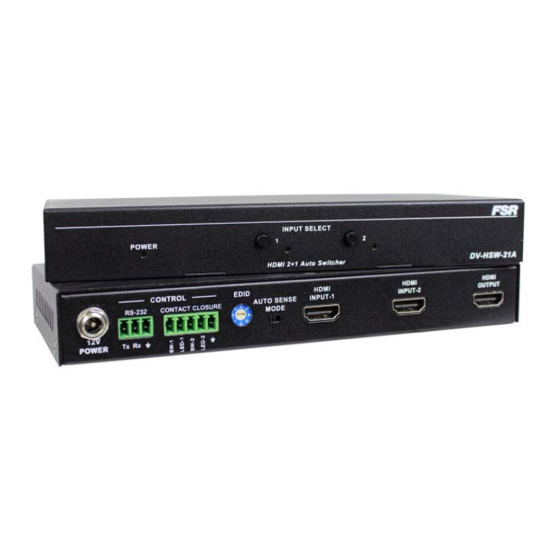
Page 8: Rear Panel
REAR PANEL DV-MFSW-21A model shown. DV-HSW-21A has two HDMI (no VGA) input connectors and no audio input connector Name Description Power 12VDC power input RS232 control. RS232 For the API commands, please refer to DV-MFSW-21A or DV-HSW-21A RS-232 Serial Protocol Connects to a control device such as keypad for switching between HDMI IN 1 and PC IN 2. - Page 9 The input is manually selected by the input select switch, contact closure or serial command. Connects to an HDMI source (Two HDMI HDMI INPUT inputs on DV-HSW-21A model) Audio binding VGA channel, embedded in VGA + Audio HDMI signal output INPUT...
-
Page 10: Hardware Installation
HARDWARE INSTALLATION DV-MFSW-21A model shown. DV-HSW-21A has two HDMI (no VGA) input connectors and no audio input connector Connect the HDMI or VGA input source (such as DVD Player, Apple TV, and STB) to the unit. Connect the HDMI display device (such as HD-LCD) to the HDMI output port of the switcher. -
Page 11: Edid Management
1920x1080 60Hz (default) 1280x720 60Hz 1024x768 60Hz 800x600 60Hz Reserved Reserved DV-HSW-21A EDID for both inputs. Position Functions Automatically copy HDMI display's EDID to all HDMI Inputs, if failed, the EDID of all HDMI inputs won’t change. 4K2K 30Hz 2CH (default) -
Page 12: Rs-232 Operation
RS-232 OPERATION The switchers may be configured or queried via the RS232 serial connection. Baud Rate: 38,400bps Data bits: 8 Stop bits: 1 Parity: None Flow control: None Computer (DTE) DV-HSW-21A / DV-MFSW-21A Pin 2 Rx Pin 3 Tx — Pin 5 Ground Ground RS-232 SERIAL PROTOCOL The DV‐MFSW‐21A and the DV‐HSW‐21A switcher may be configured or ... -
Page 13: Command Request Syntax
as the entire command is less than 80 characters. A <cr> terminates the command. Below is an example describing a command. <cr> So the actual message would look like this: CON 2<cr> Command Request Syntax: This document uses the following notation when describing the syntax of a command request: BOLD – identifies the command lower case – identifies data to be entered which is described in the text following the syntax description " " ‐ entry defined within double quotes is to be entered exactly as shown < > ‐ entry defined within these brackets is required [ ] ‐ entry defined within these brackets is optional { } ‐ entry defined within curly brackets must be entered at least once | ‐ a vertical bar denotes a logical choice of entry ... -
Page 14: Acknowledging Receipt Of Commands
Acknowledging Receipt of Commands Each request sent to the switcher will have by default two possible responses, an acknowledgement of a correct request or an error response. The acknowledge response will be: Ok<cr><lf> Error Response It is inevitable that errors occur in the requests sent to the switcher. If an invalid command is sent to the switcher, the switcher will respond with the message "ERR: unknown command". If an invalid parameter is sent to the switcher, the switcher will respond with the message "ERR:" followed by the valid syntax for the errored entry. Example: A connect request with an incorrect input number: CON 3<cr> The error response would be: ERR: CON 3<cr> REQUEST LIST QUICK REFERENCE REQUEST DESCRIPTION ... -
Page 15: Connection Request
Connection Request The connection request is used to connect one of the two available inputs to the output. A connection may be disconnected by using the DIS command (see later in document). input | "?" <cr> Syntax: CON <input | "?"><cr> Where: CON Connection request header input Input number in the range 1‐2 "?" Request to return the currently selected input (the front panel LEDs reflect the currently selected input). (Note: A CON input command will override the disconnected output, ie via the DIS command. See below for description of DIS command.) Examples: To connect input 2 to output, the connection request would look like this: ... -
Page 16: Disconnect Request
Disconnect Request The disconnect request is used to disconnect (disable) the output of the switcher. <cr> Syntax: DIS<cr> Where: DIS Disconnect request header Example: To disconnect (disable) the output of the switcher, the user would send the following message: DIS<cr> HDCP Request The High‐bandwidth Digital Content Protection status request allows identification of the presence of HDCP on the input(s). The format for the HDCP request is as follows: HDCP <cr> Syntax: HDCP<cr> Where: HDCP High Definition Content Protection request header ... -
Page 17: Model Request
Example: To query the HDCP status of the unit the user would send the following message: HDCP<cr> The response for the DV‐MFSW‐21A switcher could be: HDCP 1<cr><lf> That is, HDCP is present on input 1. The response for the DV‐HSW‐21A switcher could be: HDCP 01<cr><lf> That is, HDCP is not present on input 1 and HDCP is present on input 2. Model Request The MOD Model request allows identification of the model number of the switcher. The unit will return the current model identification, ie DV‐MFSW‐21A. The format for the model request is as follows: <cr> Syntax: MOD<cr> Where: MOD Model request header Example: To query the model number of the unit the user would send the following message: ... -
Page 18: Reconnect Request
Reconnect Request The REC request allows the user to reconnect the disconnected output to the currently selected input. Note that the input to be reconnected is as indicated by the input LED on the front panel. The command has no effect if an input is already connected to the output. <cr> Syntax: REC<cr> Where: REC Reconnect request header Example: To reconnect the previously connected input 2 to output, the user would send the following message: REC<cr> Status Request The STA request returns the presence of signal on the respective inputs, 1 = signal present, 0 = no signal present. <cr> Syntax: STA<cr> Where: STA Status request header Example: ... -
Page 19: Version Request
would be: STA 10<cr><lf> If signal were not present on input 1 and present on input 2, the response from the switcher would be: STA 01<cr><lf> Version Request In order to be able to identify the current firmware version populated in the unit, the user may request using the VER request. The format for the request will be as follows: <cr> Syntax: VER<cr> Where: VER Version Request header Response form DV‐MFSW‐21A: VER DV‐MFSW‐21A <XX.xx> Response form DV‐HSW‐21A: VER DV‐HSW‐21A <XX.xx> Where: XX.xx XX = Major version number, xx = Minor version number Example: VER<cr> To which the DV‐MFSW‐21A switcher will respond: VER DV‐MFSW‐21A 01.09<cr> ... -
Page 20: Specifications
SPECIFICATIONS DV-HSW-21A / DV-MFSW-21A Video Input 2 x HDMI Type A 19-pin, female( DV-HSW-21) 1 VGA and 1 HDMI (DV-MFSW-21 only) Audio Input 3.5mm Stereo (DV-MFSW-21 only) Video Output 1 x HDMI Type A 19-pin, female RS-232 3 Pin Pluggable Screw Terminal... -
Page 21: Limited Warranty
FSR factory or Authorized Repair Stations. This warranty shall be cancelable by FSR at its sole discretion if the Unit has been subjected to physical abuse or has been modified in any way without written authorization from FSR.
Need help?
Do you have a question about the DV-HSW-21A and is the answer not in the manual?
Questions and answers