
Related Manuals for Digitus DN-80223


Summary of Contents for Digitus DN-80223
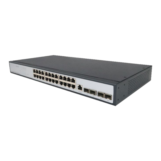
- Page 1 24 Port 10/100/1000 + 4 SFP + UPLINK Switch, 19", L2 + Features Quick Installation Guide DN-80223...
- Page 2 1. Introduction Digitus DN-80223, with its 24 Gigabit RJ45 port and four independent SFP + fiber expansion slot, is ideal for connecting local networks to data centers. Equipped with 4x 10G SFP + slot, flexibly expand your network. The 10G uplink switch provides high performance, enterprise QoS, advanced security policies and comprehensive layer 2 + management features.
-
Page 3: Package Content
3. Package Content 24 Port RJ45, 4 10G SFP + Uplink Switch Power Cord Manual 4. Specifications 24-Port Gigabit+4x 10G SFP + Managed Model Switch IEEE 802.3, IEEE 802.3u, IEEE 802.3ab, IEEE 802.3z, IEEE 802.3x, IEEE 802.1X, Standard IEEE 802.1q, IEEE 802.1p, IEEE 802.1d, IEEE 802.1w, IEEE 802.3ad... -
Page 4: Hardware Description
Power Input AC: 100~240V 50/60Hz Operating Temperature: 0°C ~ 40 °C (32 °F ~104°F ) Temperature Storage Temperature: -40 °C ~ 70 °C (-40 °F ~158°F ) Operating Humidity: 10% ~ 90% non-condensing Humidity Storage Humidity: 5% ~ 90% non-condensing 5. - Page 5 Blink: Indicates that the Switch is actively sending or Receiving data over that port. 5.2 Rear Panel The rear panel of a switch shows the AC power interface. The power input ranges from 100 v AC to 240V AC at 50/60 Hz. Grounding Column Power Socket Power Socket...
- Page 6 Do not place the switch near water or any damp area. Prevent water or moisture from entering the switch chassis Do not place the switch on an unstable case or desk. The switch might be damaged severely in case of a fall Ensure proper ventilation of the equipment room and keep ...
- Page 7 move the switch along the guide rails to a proper position. Then, use screws to fix mounting ears to the guide rails at both ends of the cabinet. Ensure that the switch is securely installed on the tray in the cabinet slot. The mounting ear of the device is not used for weight bearing, it is only used for fixation.
-
Page 8: Console Port Interface
automatically initializes. If all port indicators are on and off, the system is successfully reset. The power LED indicator is steady Note: Please confirm the voltage is correct before power on, otherwise the switch will be damaged. (The power input is: 100V-240Vac, 50/60Hz.) 7. - Page 9 plug, the other end is a 25-hole plug (DB25) and 9-hole plug (DB9), RJ45 head into the switch’s console port socket, DB25 and DB9 can be used according to the requirements of the terminal serial port, the cable internal connection schematic as follows: 8.
- Page 10 3. Open the browser, enter http://192.168.2.1 in the address bar, then press the Enter key to open the web login interface. (Please make sure the browser version is up to date) 4. In the web login interface of the switch, enter the login user name, login password, and click login to enter the switch web control interface.
- Page 11 Note: For more details about how to configure the switch, see the User Guide on the webshop. CE Mark Warning: This is a Class A product. In home environment, this product may cause radio interference. In this case, the user may be required to take appropriate measures. Hereby Assmann Electronic GmbH, declares that the Declaration of Conformity is part of the shipping content.
Need help?
Do you have a question about the DN-80223 and is the answer not in the manual?
Questions and answers