Table of Contents
Advertisement
Quick Links
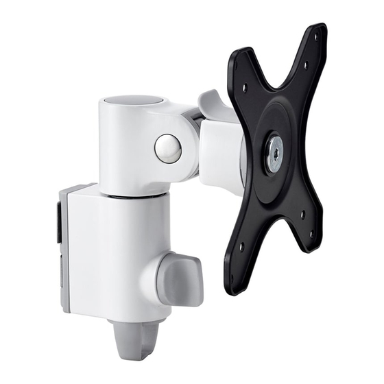
130 Arm
COMPONENT CHECKLIST
A
Monitor Arm
(x1)
IMPORTANT INFORMATION
! Please ensure this product is installed as per these installation instructions.
! Do not remove/ throw away the plastic cap on channel clamp.
! The manufacturer accepts no responsibility for incorrect installation.
! This product is compatible with Atdec AWM Series products.
! Curved monitors, deep devices (such as all-in-one PCs), VESA mounted accessories (such as mini PC brackets and mounts), and
offset VESA locations exert additional leverage that can exceed the capacity of the mount even though the monitor weight may be
within the stated range. Please contact Atdec if you would like further information.
D
Screw
M4x25mm
(x4)
B
VESA Head
(x1)
G
Spacer
(x4)
E
F
Screw
Screw
M4x16mm
M4x12mm
(x4)
(x4)
H
I
Security
4mm
Screw
Hex Key
(x1)
(x1)
Installation Guide
AWM-A13
REQUIRED TOOLS
• Phillips Head Screwdriver
WEIGHT RANGE
Flat Monitors
0 - 12kg
(0 - 26.5lbs)
Curved Monitors
0 - 8kg
(0 - 17.5lbs)
Monitor weight should be within the
weight range of all modular elements
that make up the complete monitor
mounting solution.
AWM-A13 Page 1 of 4
Advertisement
Table of Contents

Related Manuals for Atdec AWM-A13


Summary of Contents for Atdec AWM-A13
- Page 1 ! Curved monitors, deep devices (such as all-in-one PCs), VESA mounted accessories (such as mini PC brackets and mounts), and offset VESA locations exert additional leverage that can exceed the capacity of the mount even though the monitor weight may be within the stated range. Please contact Atdec if you would like further information. AWM-A13 Page 1 of 4...
- Page 2 2.6. Fit tilt head back 2.7. Ensure tilt head is 2.8. Tighten joint screw. onto channel clamp. fully pushed onto shaft. NOTE: Check the rotation is smooth after tightening. NOTE: Ensure plastic sleeve is on shaft before fitting arm. AWM-A13 Page 2 of 4...
- Page 3 5.1. Use the allen key to adjust the tilt tension until the 5.2. (OPTIONAL) To install the optional security monitor holds in a vertical position at the end of the arm. screw tilt the head upwards. NOTE: Support monitor while adjusting Loosen Loosen Tighten Tighten AWM-A13 Page 3 of 4...
- Page 4 No portion of this document or any artwork contained herein should be reproduced in any way without the express written consent of Atdec Pty Ltd. Due to continuing product development, the manufacturer reserves the right to alter specifications without notice. ©20220830...
Need help?
Do you have a question about the AWM-A13 and is the answer not in the manual?
Questions and answers