Advertisement
Quick Links
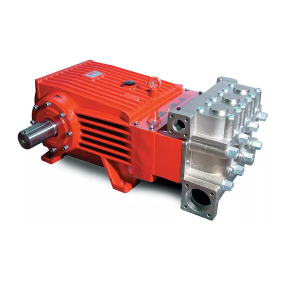
Models
GP8055, GP8055-1000,
GP8060, GP8060-1000,
GP8065 and GP8065-1000
Updated 10/20
Contents:
Installation Instructions:
Pump Specifications:
Exploded View/Parts List:
Repair Kits/Tool List:/Torque Specifications
Troubleshooting Chart:
Repair Instructions:
Dimensions:
Warranty Information
Triplex Ceramic
Plunger Pump
Models Manual
page 2
page 3-5
pages 6-7
page 8
page 8
pages 9-11
back page
back page
Advertisement

Subscribe to Our Youtube Channel
Related Manuals for Giant GP8055


Summary of Contents for Giant GP8055
- Page 1 Triplex Ceramic Models Plunger Pump Models Manual GP8055, GP8055-1000, GP8060, GP8060-1000, GP8065 and GP8065-1000 Contents: Installation Instructions: page 2 Pump Specifications: page 3-5 Exploded View/Parts List: pages 6-7 Repair Kits/Tool List:/Torque Specifications page 8 Troubleshooting Chart: page 8 Repair Instructions:...
-
Page 2: Installation Instructions
“dry” for 1-2 minutes for this purpose. To empty the cooling circuit, remove the L-joints (K11) on the Oil: Use only 3.3 gallons (12.5 liters) of Giant Oil (p/n 01154) pump head (50). Blow out the circuit liquid at the joint connec- or ISO VG 220 GL4 (e.g. -
Page 3: Specifications
Discharge Ports ............... (2) 1-1/4” BSP Weight ............749 lbs....(340 kg) Crankcase Oil Capacity ......3.3 Gal....(12.5 liters) Valve Casing Material (GP8055) ..........Nickle plated Spheroidal Cast Iron Valve Casing Material (GP8055-1000) ........Aluminum-Bronze NPSHR ............. 23.0 ft.-head ..7.0 mWs *higher water temperatures possible with separate crankcase cooling system;... - Page 4 Valve Casing Material (GP8060-1000) ........Aluminum Bronze NPSHR ............. 26.2 ft.-head ..8.0 mWs *higher water temperatures possible with separate crankcase cooling system; contact Giant. Consult the factory for special requirements that must be met if the pump is to operate beyond one or more of the limits specified above.
- Page 5 Valve Casing Material (GP8065-1000) ........Aluminum Bronze NPSHR .............23.6 ft.-head ..7.2 mWs *higher water temperatures possible with separate crankcase cooling system; contact Giant. Consult the factory for special requirements that must be met if the pump is to operate beyond one or more of the limits specified above.
- Page 6 Exploded View - GP8055(-1000), GP8060(-1000), GP8065(-1000)
- Page 7 Part List - GP8055 (-1000), GP8060 (-1000), GP8065 (-1000) Item Part Description Item Part Description 05380 Crankcase 05278 Sleeve Support Ring (GP8055) 06893 Oil Filler Plug Assy with Vent 05070 Sleeve Support Ring (GP8060) 22929 Copper Washer 05118 Sleeve Support Ring (GP8065) 12256 Plug, 3/8”...
- Page 8 GP8065 - #09586 Item Part # Description Qty. 06667 O-Ring 05066 O-Ring 06996 Seal Ring 06997 V-Sleeve GP8055/GP8060/GP8065 TOOL LIST AND TORQUE SPECIFICATIONS ITEM PART # DESCRIPTION TORQUE Ft-lbs (NM) TOOL NEEDED 05038 Hexagon Socket Screw 64 (87) 10mm allen wrench...
- Page 9 GP8055(-1000)/GP8060(-1000)/GP8065(-1000) PUMP REPAIR INSTRUCTIONS Valve Inspection and Repair Remove bolts (58). 2) Remove discharge 3) Take out pressure springs casing (50B) up and away. (57A). Pull out assembled valves (51 & 52) with valve pull- ing tool (07662). 4) The spring tension cap (51A, 52A) is screwed together with the valve seat (51B or 52B).
- Page 10 GP8055(-1000)/GP8060(-1000)/GP8065(-1000) PUMP REPAIR INSTRUCTIONS 8) Take out the seal case (38) from the valve (if Be careful not to damage the seal necessary secure 2 screwdrivers in the front O-ring sleeve (39) and pressure ring (41). Check the inner groove to extract seal casing from valve casing).
- Page 11 GP8055(-1000)/GP8060(-1000)/GP8065(-1000) PUMP REPAIR INSTRUCTIONS To Dismantle Crankcase Gear 11) Take out plungers and seal sleeves as described 12) Remove the connecting rod screws (24). above. Drain the oil by taking off the plug (12). After Connecting rods are marked 1 to removing the clip ring (33B), pry out the seal retainer 3 for identification.
- Page 12 Liability under this warranty is on all non-wear parts and limited to the replacement or repair of those products returned freight prepaid to Giant Industries which are deemed to be defective due to workmanship or failure of material. A Returned Goods Authorization (R.G.A.) number and completed warranty evaluation form is required prior to the return to Giant Industries of all products under warranty consideration.
Need help?
Do you have a question about the GP8055 and is the answer not in the manual?
Questions and answers