Advertisement
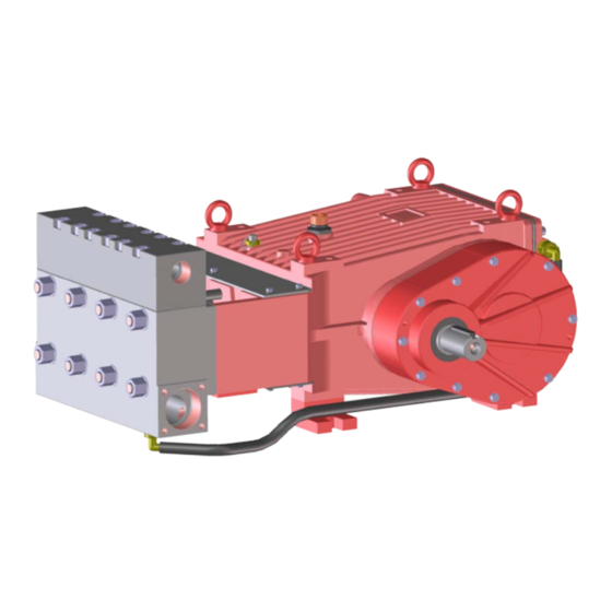
GP8135 and GP8140 Pump Repair Instructions
To Check Valves
Loosen screws (58) and lift discharge casing (50B) up and away. Take out pressure springs (57). Pull out as-
sembled valves (51 and 52) with fi tting tool (p/n 07662).
Dismantling valves: the spring tension cap (51A, 52A) is screwed together with the valve seat (51B/52B).
Remove spring tension cap, take out springs (51E/52E) and valve plate (51C/52C). Check sealing surfaces
and O-rings (51D/F, 52D/F, 56A).
Replace worn parts.
When reassembling, coat threads of valve seat with silicon grease or molycote anti-seize Cu-7439. Before
refi tting the valves, clean the sealing surfaces in the casing and check for any damage.
Tighten screws (58) at 132 Ft-lbs (180 NM); check torque tension after 8-10 operating hours.
To Check Seals and Plunger Pipe
Remove hexagon nuts (49A) and hose coupling (K11 and K15). Remove pump head together with seal case
(38) and intermediate casing (62) from crankcase (1). If necessary, carefully tap the valve casing (50) past
the centering stud (50A) using a rubber hammer.
Important! If necessary, support the pump head by resting it on wooden blocks or by using a pulley.
Take off fl at leakage seal (62D) and check to make sure that it is not torn or damaged.
Remove plunger (36) from crosshead with plunger base (25) and take seal sleeve (39) together with all
mounted parts out of the drive.
Pull plunger out of seal assembly and check for any damage. Clean centering and top-surface of crosshead
with plunger base (25). Take out tension spring (45). Carefully remove the whole seal unit (41-44) by using
socket wrench or the backside of a screwdriver. Check plunger surface and seals. Check O-rings (39).
Renew damaged parts.
After removing clip-ring (40C) and pressure ring (40B), check leakage seal (40) and O-ring (40A) . If neces-
sary, replace worn parts.
Important! Be careful not to damage seal sleeve (39), pressure ring (41) and guide ring (41A). Check the
inner diameter of the pressure ring and guide ring for wear and, if necessary, replace together with seals
(42) and support ring (44). Clean all parts. Before installation, new parts should be lightly coated with silicon
grease.
Insert the seal unit (41-45) into the seal sleeve (39). Carefully push the plunger (36) through the seals (from
the crankcase side). If necessary, the seals can be held tightly using a suitable pipe support held on the op-
posite side of the seal sleeve.
Take out the seal case (38) from the intermediate casing (62) and check O-rings (38A). If necessary, secure 2
screwdrivers in the front O-ring groove to extract seal casing from intermediate casing. Before installing, coat
O-rings with silicon grease.
Important! Mounting surfaces of the crankcase, seal sleeves, intermediate casing and valve casing must be
clean and free of damage. The components must fi t exactly and evenly on one another. The same exactness
applies for all centering positions in the crankcase, intermediate casing, pressure-and valve casing.
Coat the seal sleeve lightly with anticorrosive grease (e.g. molycote no. Cu-7439) in its fi tted area towards the
crankcase. Insert seal sleeves in to their crankcase fi ttings.
Important! Watch the even milled surfaces on the seal sleeves. They must be positioned vertically on each
other.
Turn the pump (by hand) until the plunger base (25) rests against the plunger (36). Tighten plunger (36) to 33
Ft-lbs. (45 NM).
Insert the seal tension spring (45) in to the seal sleeve (39).
9
Advertisement
Table of Contents

Related Manuals for Giant GP8135


Summary of Contents for Giant GP8135
- Page 1 GP8135 and GP8140 Pump Repair Instructions To Check Valves Loosen screws (58) and lift discharge casing (50B) up and away. Take out pressure springs (57). Pull out as- sembled valves (51 and 52) with fi tting tool (p/n 07662). Dismantling valves: the spring tension cap (51A, 52A) is screwed together with the valve seat (51B/52B).
- Page 2 GP8135 and GP8140 Pump Repair Instructions Mounting Valve Casing: Press seal cases (38) (with the stepped OD diameter 65mm) carefully to its stop in the centering holes of the intermediate casing. Mount fl at leakage seal (62D). Important! The fl at leakage seal (62D) must be positioned with its 3mm diameter bore onto the notched pin (62C) on the intermediate casing.
Need help?
Do you have a question about the GP8135 and is the answer not in the manual?
Questions and answers