Advertisement
Model
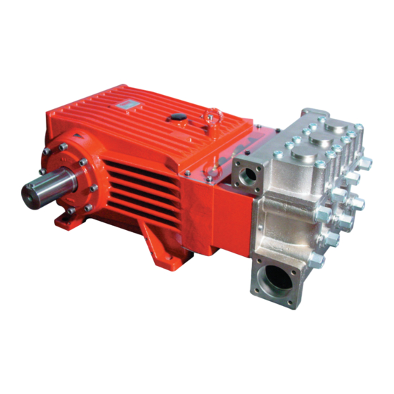
GP8076
Contents:
Pump Specifi cations:
Installation Instructions:
Exploded View/Parts List:
Parts List:
Repair Kits/Tool List:/Torque Specifi cations
Repair Instructions:
Dimensions:
Warranty Information
Triplex Ceramic
Plunger Pump
Models Manual
page 2
page 3
page 4
page 5
page 6
page 7
back page
back page
Advertisement
Table of Contents

Related Manuals for Giant GP8076


Summary of Contents for Giant GP8076
- Page 1 Triplex Ceramic Model Plunger Pump Models Manual GP8076 Contents: Pump Specifi cations: page 2 Installation Instructions: page 3 Exploded View/Parts List: page 4 Parts List: page 5 Repair Kits/Tool List:/Torque Specifi cations page 6 Repair Instructions: page 7 Dimensions: back page Warranty Information back page...
- Page 2 Specifi cations - GP8076 1. Performance U.S. (Metric) Flow ..............132 GPM ....(500 LPM) Discharge Pressure ......... 1500 PSI ....(100 bar) Power Consumption ........129 BHP ....96 kW Maximum Speed ................520 RPM Inlet Pressure ..........29 PSI ..... (2.0 bar) Plunger Diameter ..........2.99” ......76 mm Plunger Stroke ..........2.83” ......72 mm Crankshaft Diameter .
- Page 3 5. Installation/ Putting into Operation 5.5 Valve Casing The torque tension on the valve casing 5.1 Shaft protector nuts (49A) is to be checked after When the pump is in operation, the driven shaft side approximately 200 operating hours. and coupling by a shaft guard and the plunger room Please see the section ‘Maintenance by cover (30). and Servicing’ concerning the torque Do not step onto the protective plate (30) nor put values. heavy objects on it. The pump must be at zero pressure when checking 5.2 Direction of pump rotation the torque tension. An arrow on the pump crankcase indicates the recommended direction of rotation for the drive shaft. 6. Operation The indicated direction ensures that oil is correctly When starting up for work, the pump must run fi rst distributed on and into the crosshead guides via at zero pressure for approximately 1 minute. optimal connecting rod motion thus providing best possible lubrication particularly with regard to The pump and cooling system must be continuous operation.
- Page 4 Exploded View - GP8076...
- Page 5 Part List - GP8076 Item Part Description Item Part Description 05380 Crankcase 03567 Guide Ring 06893 Oil Filler Plug Assy with Vent 1 03568 Spiral Ring 22929 Copper Washer 03569 Pressure Spring 12256 Plug, 3/8” BSP 05072 Stud Bolt 05656 Plug for Oil Dipstick 49A 05073 Hexagon Nut 05035 Oil Dipstick Assembly 03570 Valve Casing 01009 O-Ring 50A 13162...
- Page 6 GP8076 PUMP REPAIR KITS Plunger Packing Kit - #09861 Valve Repair Kit - #09862 Item Part # Description Qty. Item Part # Description Qty. 38A 03564 O-Ring 51B 03574 Valve Seat 39A 05066 O-Ring 51C 03575 Valve Plate 03566 Support Ring 51D 06560 O-Ring 03567 Guide Ring...
- Page 7 Pull plunger pipe out of seal assembly and check for studs (50A). any damage. Tighten hexagon nuts evenly and crosswise to the Pull out spiral rings (42), guide rings (41) and support required torque. rings (40) and check for any damage. The torque tension on the screws (49A) must be checked after 8-10 operating Be careful not to damage seal sleeve (39) hours; the pump must be at zero and guide ring (41). pressure. Check the inner diameter of the guide ring Thereafter the tension is to be checked for wear and if necessary replace together every 200 operating hours. with spiral ring (42) and support ring (40). If required, supplementary assembly instructions Clean all parts. New parts should be lightly coated with can be requested from the manufacturer Giant silicon grease before installation. Industries. Insert the seal unit (40, 41, 42, 43) into the sleeve. Push the ceramic plunger carefully through the seals from the crankcase side. If necessary, the seals can be held tightly using a suitable pipe support held on the other side of the seal sleeve.
- Page 8 GP8076 PUMP DIMENSIONS - (mm) GIANT INDUSTRIES LIMITED WARRANTY Giant Industries, Inc. pumps and accessories are warranted by the manufacturer to be free from defects in workmanship and material as follows: 1. Five (5) years from the date of shipment for all pumps used in portable pressure washers with NON-SALINE, clean water applications. 2. Two (2) years from the date of shipment for Giant pumps used in car wash applications. 3. One (1) year from the date of shipment for all other Giant industrial and consumer pumps. 4. Six (6) months from the date of shipment for all rebuilt pumps 5. Ninety (90) days from the date of shipment for all Giant accessories. This warranty is limited to repair or replacement of pumps and accessories of which the manufacturer’s evaluation shows were defective at the time of shipment by the manufacturer. The following items are NOT covered or will void the warranty: 1. Defects caused by negligence or fault of the buyer or third party. 2. Normal wear and tear to standard wear parts. 3. Use of repair parts other than those manufactured or authorized by Giant. 4. Improper use of the product as a component part. 5. Changes or modifi cations made by the customer or third party. 6. The operation of pumps and or accessories exceeding the specifi cations set forth in the Operations Manuals provided by Giant Industries, Inc.
Need help?
Do you have a question about the GP8076 and is the answer not in the manual?
Questions and answers