Advertisement
Quick Links
Advertisement

Subscribe to Our Youtube Channel
Related Manuals for Elumen8 Evora Zoom Spot CMY300


Summary of Contents for Elumen8 Evora Zoom Spot CMY300
- Page 1 Evora CMY300 Zoom Spot User Manual Order codes: ELUM027...
- Page 2 Safety advice WARNING FOR YOUR OWN SAFETY, PLEASE READ THIS USER MANUAL CAREFULLY BEFORE YOUR INITIAL START-UP! • Before your initial start-up, please make sure that there is no damage caused during transportation. • Should there be any damage, consult your dealer and do not use the equipment. •...
- Page 3 Safety advice This fixture falls under Protection Class 1, therefore it has to be connected to a mains socket with a protective earthing connection. Risk group 2, RG-2: CAUTION! Do not stare at exposed LED in operation as it may damage/be harmful to the eyes.
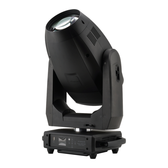
- Page 4 Product overview & technical specifications Evora CMY300 Zoom Spot The Evora CMY300 Zoom Spot moving head boasts an immensely bright 300W LED with crystal clear optics, and with adjustable beam angle from 4.5° to 38° it can achieve tight beams through to wide washes. This feature packed head offers both static and rotating gobo wheels, linear and circular prisms, variable frost filter, high CRI filter along with motorised zoom, focus and iris.
- Page 5 Technical specifications 220mm 103mm 355mm 230mm 278mm 370mm 422mm www.prolight.co.uk Evora CMY300 Zoom Spot User Manual...
- Page 6 Technical specifications In the box: 1 x fixture, 01 - LCD display 05 - EtherCON input 2 x omega clamps, 02 - Function buttons 06 - EtherCON output 09 - Fuse T5A 250V 1 x gobo pack 03 - 5-Pin DMX input 07 - PowerCON TRUE1 input 10 - Wireless DMX Antenna &...
- Page 7 The installation should be checked annually by a qualified person. The eLumen8 Evora CMY300 Zoom Spot can be operated where the base of the fixture is horizontally orientated, this includes standing the fixture upright on a flat, level surface or hanging the fixture upside down.
- Page 8 Installation Installation: 1. Fasten each clamp to the omega clamps with a bolt and lock nut through the hole in the omega clamp. 2. Align and insert the omega clamp quick-lock fasteners with the respective holes on the bottom of the unit. 3.
- Page 9 Pan/Tilt Lock Mechanism Pan mechanism lock and release every 45° UNLOCKED LOCKED Tilt mechanism lock and release every 45° LOCKED UNLOCKED www.prolight.co.uk Evora CMY300 Zoom Spot User Manual...
- Page 10 Rotating Gobo Replacement Rotating Gobo Replacement: The fixture is supplied with 8 rotating, replaceable gobos. See below for installation instructions. 1) Place the fixture on a stable, flat surface ensuring you are indoors in a dust free location. Disconnect and isolate from power and let the unit cool for at least 15 minutes.
- Page 11 Rotating Gobo Replacement 4) On the prism module, find the 4-pin connector located behind the left motor, just beside the left thumbscrew (see yellow box above). Disconnect this connector. This will help improve access to the gobo wheel module. 5) Loosen the thumbscrews on the prism module, these do not come free of the prism module. Carefully slide the prism module out of its runners.
- Page 12 Rotating Gobo Replacement 6) On the gobo wheel module, locate the circuit board on the left hand side, on the right hand side find the 3-pin and 4-pin connector located behind 3 capacitors (see yellow box above), disconnect this connector. 7) Loosen the thumbscrews on the gobo wheel module, these do not come free of the gobo wheel module.
- Page 13 Rotating Gobo Replacement 8) Locate the gobo that will be replaced. Grip the edges of the gobo holder and carefully lift the holder until is raised from the surface of the gobo wheel (pictured left). Pull the gobo holder towards you, away from the gobo wheel (pictured right).
- Page 14 The LCD control panel situated on the front of the fixture allows the user to access the menu system to adjust the fixtures settings. When the unit has been powered on the display will show “Software Update” followed by “eLumen8 Evora CMY300 Zoom Spot” and then “Ethernet Reset Please Wait...” followed by “Motor Reset Please Wait...”.
- Page 15 Operating instructions Operating instructions Error Code Description The movement is not located in the default position after the reset. This message will appear if the sensor has failed or magnet is missing, or if there is a motor failure (defective motor or a defective motor IC drive on the main PCB).
- Page 16 Operating instructions Main Menu Sub Menu Options/Values (Default Settings in BOLD) Description 001-512 DMX Address DMX Address Setting Activate/deactivate Input network input ArtNET Protocol Network Protocol Setting sACN ServicePIN 000-255 (PIN = 050) Pin to enter Address Menu Universe Setting Universe 000-255 Network...
- Page 17 Operating instructions Main Menu Sub Menu Options/Values (Default Settings in BOLD) Description Pan Fine Tilt Tilt Fine Colour Macros CMY Mode Cyan Cyan Fine Magenta Magenta Fine Yellow Yellow Fine High CRI Rot Gobo Manual Control 000-255 Manual Control Settings Gobo Index Index Fine Fixed Gobo...
- Page 18 Operating instructions Main Menu Sub Menu Options/Values (Default Settings in BOLD) Description Split Colour Split Colour Setting Backlight 02M-60M (06M) LCD Backlight Setting Rotate 180° LCD Display Inverse Setting Control Panel Lock Setting Display Key Lock (Press and hold MODE for 3 seconds to unlock) Display Flash Setting DispFlash...
- Page 19 Operating instructions Main Menu Sub Menu Options/Values (Default Settings in BOLD) Description Auto Settings Fans Base Fan Base Fan Speed Setting High Tilt Cyan Magenta Yellow High CRI Colour Colour 0-1 Colour 1-2 Colour 2-3 Colour 3-4 Colour 4-5 Colour 5-6 Colour 6-7 Colour 7-8 Colour 8-0...
- Page 20 Units C°/ F° Head-1: xxxxRPM Head-2: xxxxRPM Fan Speed Fan Speed Information Base-1: xxxxRPM Information Base-2: xxxxRPM Model eLumen8 Evora CMY300 Zoom Spot Model Information RDM UID 0x09A5-xxxxxxxx RDM UID 1U: Vx.x.xx 2U: Vx.x.xx 3U: Vx.x.xx Firmware 4U: Vx.x.xx Software Version 5U: Vx.x.xx...
- Page 21 Operating instructions DMX channel modes: Channel Value Function Default Value 000-255 Pan movement (8 bit) 000-255 Pan fine (16 bit) 000-255 Tilt movement (8 bit) 000-255 Tilt fine (16 bit) Colour Wheel (split colour disabled) 000-005 Open 006-011 Colour 1 012-017 Colour 2 018-023...
- Page 22 Operating instructions Channel Value Function Default Value 5 (cont.) Colour Wheel (split colour enabled) (when split colour 128-189 Scroll clockwise (fast-slow) is enabled in the 190-193 Stop menu - see page 194-255 Scroll anti-clockwise (slow-fast) Colour Macros (See page 23) 000-005 No function 006-030...
- Page 23 Operating instructions DMX channel modes: Channel Value Function Default Value Yellow Full 000-255 Yellow (0-100%) Effect Macros 000-170 Yellow (0-100%) 171-189 Yellow (100%-open) 190-221 Scroll clockwise (fast-slow) 222-223 Stop 224-255 Scroll anti-clockwise (fast-slow) 000-255 Yellow Fine 000-255 High CRI filter (0-100%) Rotating Gobo Wheel 000-005 Open...
- Page 24 Operating instructions DMX channel modes: Channel Value Function Default Value Fixed Gobo Wheel 000-005 Open 006-014 Gobo 1 015-023 Gobo 2 024-032 Gobo 3 033-041 Gobo 4 042-050 Gobo 5 051-059 Gobo 6 060-068 Gobo 7 069-077 Gobo 8 078-086 Gobo 9 087-095 Gobo 10...
- Page 25 Operating instructions DMX channel modes: Channel Value Function Default Value 000-255 Focus (near-far) 000-255 Focus fine Iris 000-191 Iris (wide-narrow) 192-223 Pulse opening (fast-slow) 224-255 Pulse closing (slow-fast) 000-255 Frost (open-full) Prism 000-007 No function 008-087 Prism 1 088-167 Prism 2 168-255 Prism 1 &...
- Page 26 Operating instructions DMX channel modes: Channel Value Function Default Value 000-015 No function 016-024 Blackout while P/T on (hold 3s) 025-032 Blackout while P/T off (hold 5s) 033-040 Invert pan on (hold 3s) 041-048 Invert pan off (hold 5s) 049-056 Invert tilt on (hold 3s) 057-064 Invert tilt off (hold 5s)
- Page 27 Operating instructions Macro Example Cyan Magenta Yellow Colour Wheel 50% split 50% split Open 100% 50% split Open 50% split 100% Open 33% split 33% split Open 50% split 50% split Open 50% split 100% Open 100% 50% split Open 33% split 33% split Open...
- Page 28 Operating instructions 0 second fade time 1 second fade time Dimming Curve Ramp Effect Rise time (ms) Down time (ms) Rise time (ms) Down time (ms) Standard (default) Stage 1100 1540 1660 1180 1520 1860 1940 Architectural 1380 1730 2040 2120 Theatre 1580...
- Page 29 Gobos/colours Rotating gobos (in fixture): Gobo size: 15.6mmØ Image size: 12.5mmØ Gobo thickness: 0.5mm (Max. thickness if replaced 1mm) Rotating gobos (included additional pack): Gobo size: 15.6mmØ Image size: 12.5mmØ Gobo thickness: 0.5mm (Max. thickness if replaced 1mm) Static gobos: Colour wheel: BRIGHT FERN...
- Page 30 DMX setup Setting the DMX address: The DMX mode enables the use of a universal DMX controller. Each fixture requires a “start address” from 1- 512. A fixture requiring one or more channels for control begins to read the data on the channel indicated by the start address.
- Page 31 DMX setup Notice: Be sure to follow the diagrams below when making your own cables. Pin Configuration Do not connect the cables shield conductor to the ground lug or 3-Pin 5-Pin allow the shield conductor to come in contact with the XLRs Pin 1 - Ground outer casing.
- Page 32 Multiple fixture power linking Power linking: This fixture provides power linking via the power output on the rear allowing multiple units to be connected together. The maximum number of fixtures that can be connected via a 13A mains input is 4 fixtures @ 240V or 2 fixtures @ 120V (including the first fixture).
- Page 33 www.prolight.co.uk Evora CMY300 Zoom Spot User Manual...
- Page 34 www.prolight.co.uk Evora CMY300 Zoom Spot User Manual...
- Page 35 www.prolight.co.uk Evora CMY300 Zoom Spot User Manual...
- Page 36 WEEE notice Correct Disposal of this Product (Waste Electrical & Electronic Equipment) (Applicable in the European Union and other European countries with separate collection systems) This marking shown on the product or its literature, indicates that it should not be disposed with other household wastes at the end of its working life.
Need help?
Do you have a question about the Evora Zoom Spot CMY300 and is the answer not in the manual?
Questions and answers