Table of Contents
Advertisement
Quick Links
Declaration of Conformity
According to 47 CFR, Parts 2 and 15 of the FCC Rules
The following designated product:
EQUIPMENT: MAINBOARD
is a Class B digital device that complies with 47 CFR Parts 2 and 15 of the FCC
Rules. Operation is subject to the following two conditions:
1. This device may not cause harmful interference.
2. This device must accept any interference received, including interference that
may cause undesired operation.
This declaration is given to the manufacturer:
CHAINTECH-EXCEL COMPUTER INC.
4427 Enterprise St. Fremont, CA 94538, U.S.A.
http://www.chaintechusa.com
Chaintech President: Simon Ho
Signature:
Advertisement
Table of Contents

Related Manuals for CHAINTECH CT-7NIF4


Summary of Contents for CHAINTECH CT-7NIF4
- Page 1 1. This device may not cause harmful interference. 2. This device must accept any interference received, including interference that may cause undesired operation. This declaration is given to the manufacturer: CHAINTECH-EXCEL COMPUTER INC. 4427 Enterprise St. Fremont, CA 94538, U.S.A. http://www.chaintechusa.com Chaintech President: Simon Ho Signature:...
- Page 2 AMD® Socket A NVIDIA nForce 2 IGP+ MCPS u-ATX Motherboard User’s Guide...
- Page 3 Federal Communications Commission Statement This device complies with FCC Rules Part 15. Operation is subject to the following two conditions: * This device may not cause harmful interference. * This device must accept any interference received, including interference that may cause undesired operation. This equipment has been tested and found to comply with the limits for a Class B digital device, pursuant to Part 15 of the FCC Rules.
-
Page 4: Table Of Contents
TABLE OF CONTENTS Chapter 1 Introduction....................1 1-1 Product Specifications ..................1 1-2 Package Contents ....................3 1-3 Motherboard Layout ....................4 Chapter 2 Hardware Setup ..................5 2-1 Installing a CPU Processor for Socket A ............5 2-2 Setting Your CPU’s Performance: ...............6 2-3 Main Memory Configuration................9 2-4 Connector and Jumper Reference Chart ............10 2-5 Connector and Jumper Settings................. - Page 5 4-2 Graphic Card Driver ..................37 4-3 DirectX 9.0b Install ...................37 Chapter 5 How to update your BIOS?..............38 NOTE ..........................40...
- Page 6 Revision History Revision Description V.1S_E Original Issue 9415230110...
-
Page 7: Chapter 1 Introduction
Chapter 1 Chapter 1 Introduction 1-1 Product Specifications - Supports AMD Socket-A Athlon XP/Duron/Sempron CPU - System Clock supports 200/266/333/400MHz Chipset - NVIDIA nForce2 IGP + MCPS Memory - Three 184-pin DDR DIMMs up to 3GB - Supports Dual-Channel DDR266/333/400 SDRAM modules (UMA DDR333) Expansion Slots - One AGP slot for 4X/8X AGP - Three 32-Bit PCI slots (v2.2 compliant) - Page 8 Chapter 1 USB2.0 - Build-in nForce2 MCPS supports total 8 USB 2.0/1.1 ports - Supports USB 2.0 High-Speed Device @480 Mb/s Transfer Rates Fast Ethernet - Supports 10/100Mb Fast Ethernet with external PHY Boot-Block Flash ROM - Award system BIOS supports PnP, APM, DMI, ACPI, & Multi-device booting features Rear Panel I/O ports - PS/2 Mouse and Keyboard port...
-
Page 9: Package Contents
Chapter 1 1-2 Package Contents This product comes with the following components: Motherboard I / O Panel 40-Pin UDMA-100 IDE Cable Blue to motherboard, Gray to Master and Black to Slave. 34-Pin floppy Disk Drive Cable Manual Driver CD Includes: VGA Drivers Audio drives and utility LAN Drivers... -
Page 10: Motherboard Layout
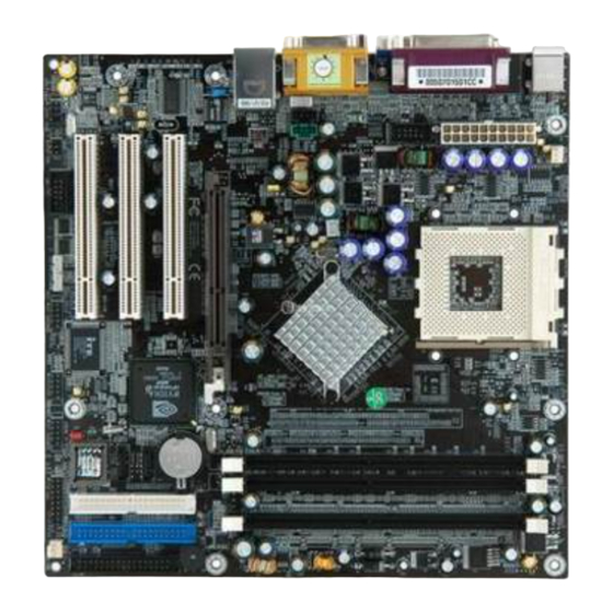
Chapter 1 1-3 Motherboard Layout... -
Page 11: Chapter 2 Hardware Setup
Chapter 2 Chapter 2 Hardware Setup If your motherboard has already been installed in your computer you may still need to refer to this chapter if you plan to upgrade your system’s hardware. This motherboard is electrostatic sensitive. Do not touch without wearing proper safety gadget and make sure to disconnect the power cable from the power source before performing any work on your motherboard. -
Page 12: Setting Your Cpu's Performance
Chapter 2 2-2 Setting Your CPU’s Performance: Frequency Configuration: If you install a CPU on this motherboard, you must set the [Front Side Bus Frequency] JP25 according to your processor. CPU Speed = Multiplier x CPU Frequency You do not need to make voltage settings because this board will automatically set your CPU voltage. - Page 13 Chapter 2 1000 1000MHz 10.0 1.75V 256KB 0.18 1100 1100MHz 11.0 1.75V 256KB 0.18 1200 1200MHz 12.0 1.75V 256KB 0.18 1300 1300MHz 13.0 1.75V 256KB 0.18 1400 1400MHz 14.0 1.75V 256KB 0.18 1000 1000MHz 1.75V 256KB 0.18 1113 1113MHz 1.75V 256KB 0.18 1200 1200MHz...
- Page 14 Chapter 2 AMD Sempron CPU Micron Model CPU Speed Multiplier Vcore Frequency Cache process 2200+ 1.5GHz 1.6V 256KB 0.13 2300+ 1.583GHz 1.6V 256KB 0.13 2400+ 1.667GHz 10.0 1.6V 256KB 0.13 2500+ 1.750GHz 10.5 1.6V 256KB 0.13 2600+ 1.833GHz 11.0 1.6V 256KB 0.13 2800+...
-
Page 15: Main Memory Configuration
Chapter 2 2-3 Main Memory Configuration This motherboard provides 3 184pin Double Data Rate (DDR) Dual Inline Memory Modules (DIMM) slots. Which supports PC 1600/DDR200, PC2100/DDR266, PC2700/DDR333 and PC3200/DDR400 DDR SDRAM modules up to 3GB. To support Dual-Channel DDR400 please use an additional VGA card to prevent the onboard VGA to share the system memory. -
Page 16: Connector And Jumper Reference Chart
Chapter 2 2-4 Connector and Jumper Reference Chart Jump Connector Function Page PW 1 u-ATX Power Supply Connector Floppy Connector IDE 1/2 IDE Hard-Disk Connector SATA 1/2 SATA Hard-Disk Connector FAN 1/3 CPU/ Case FAN Connector (12V) FAN 4 North Bridge Cooling Fan Power Connector (12V) CMOS Clear Jumper Keyboard Power on Function Jumper Disable/Enable USB 0/1 Device Power ON Jumper... -
Page 17: Connector And Jumper Settings
Chapter 2 2-5 Connector and Jumper Settings Connectors are used to link the system board with other parts of the system, including the power supply, the keyboard, and the various controllers on the front panel of the system case. The power supply connector is the last connection to be made while installing a motherboard. - Page 18 Chapter 2 Power-On By Modem: While in Soft-Off state, if an external modem ring-up signal occurs, the system wakes up and can be remotely accessed. You may enable this function in BIOS's Power Management Setup menu. (See section 3). Blinking LED in Suspend Mode: While in Suspend mode, the LED light on the front panel of your computer will flash.
- Page 19 Chapter 2 IDE 1/2 (IDE Hard-Disk Connector) This connector is used for connecting 40 pins of ATAPI devices. IDE 1 only connects two IDE devices. (Primary Master/Slave) IDE 2 only connects two IDE devices. (Secondary Master/Slave) SATA1/2 These SATA connectors (SATA1 – SATA2) support Serial ATA 150. Each SATA connector can only support one serial ATA device.
- Page 20 Chapter 2 FAN1 / FAN3 (CPU/Case Cooling Fan Connectors [12V]): The board's management extension hardware is able to detect the CPU fan speed in rpm (revolutions per minute). The wiring and plug may vary depending on the manufacturer. On standard fans, the red is positive (+12V), the black is ground, and the yellow wire is the rotation signal.
- Page 21 Chapter 2 JP1 (CMOS Clear Jumper): Definition 1-2 Normal (default) 2-3 Clear CMOS Data There is a CMOS RAM on board that has a power supply from external battery to keep the data and system configuration. To clear the contents of the CMOS, please follow the steps below.
- Page 22 Chapter 2 JP6 (Enable/Disable USB 0/1 Device Power ON Jumper) Definition 1-2 Disable (default) Enable A USB keyboard hot key or a USB mouse click can turn on this motherboard. To use this function, select [Enable] at the USB Resume from S3 under Wake Up Events in the BIOS's Power Management setup screen.
- Page 23 Chapter 2 CN1A (Front Panel Connector): 1. PWR-SW (Over-ride Power Button Connector): The power button on the ATX chassis can be used as a normal power switch as well as a device to activate Advanced Power Management Suspend mode. This mode is used for saving electricity when the computer is not in use for long periods of time.
- Page 24 Chapter 2 5. SPEAKER (Speaker Connector): This 4-pin connector connects to the case-mounted speaker. 6. HD-LED (IDE Activity LED Connector): The IDE activity LED lights up whenever the system reads/writes to the IDE devices. CN2/2A (CD-ROM Audio-in Connector): Use the audio cable enclosed with your CD-ROM disk drive to connect the CD-ROM drive onto your motherboard.
- Page 25 Chapter 2 CN13 (S/PDIF Connector) This connector must be connected to a S/PDIF bracket. This will allow you to use the S/PDIF function. CN5 [WOL (Wake-on-LAN) Connector]: Enable the Wake Up On LAN selection in BIOS's Power Management Setup Menu to use this function.
- Page 26 Chapter 2 CN5A [WOM (Wake-on-Modem) Connector]: The Wake Up On Modem selection in BIOS's Power Management Setup Menu must be enabled to use this function. This header is used to connect an add-in modem card, which gives WOM capability to the motherboard. CN23/23A/23B (USB Connector for USB 2/3, 4/5 and 6/7) If you want to use a USB Keyboard, you must enable the USB keyboard support function in BIOS's Integrated Peripherals menu (See Section 3).
- Page 27 Chapter 2 CN24 (Front Audio Connector): This connector give you the option of a front panel audio jack cable ext. to be plug into a special custom designed system case. Simply remove the two jumper caps at pin [5-6] and [9-10] then plug it into the (optional) cable ext. connector. Pin [5-6] and [9-10] are shorted (default) to enable the back panel audio function.
- Page 28 Chapter 2 COM 2 (Serial port / COM Headers) This is an addition 9-pin connector is for a serial port ribbon cable. This will allow you to enable an additional COM Port.
-
Page 29: Chapter 3 Bios Setup Program
Chapter 3 Chapter 3 BIOS Setup Program Phoenix-Award BIOS ROM has a built-in setup program that allows users to modify the basic system configuration. This information is stored in CMOS RAM so that it can retain the setup information, even when the power is turned off. To enter the Phoenix-Award BIOS setup program press the [Delete key] when you Power on or reboot the computer system. -
Page 30: Advanced Bios Features
Chapter 3 IDE (Primary/Secondary; Master/Slave): This category identifies up to four IDE hard disk drives that have been installed in the computer. This section does not show information on other IDE devices such as CD-ROM drives or other hard drive type such as SCSI drives. Drive A/B: Select different Floppy device Model. - Page 31 Chapter 3 On Self Test). BIOS will save time by skipping some items during POST. It is recommended that you disable this setting. Discovering a problem during boot up is better than loosing data during your work. First/Second/Third/Boot Other Device: This option sets the sequence of drives BIOS attempts to boot from after POST completes.
-
Page 32: Advanced Chipset Features
Chapter 3 take advantage of this function. See Section 3.11 for password setting information. When the Security Option is set to System, a password must be entered to boot the system or enter the BIOS setup program. When the Security Option is set to Setup, a password is required to enter the BIOS setup program. - Page 33 Chapter 3 AGP Aperture Size (MB) This function determines the amount of system memory that is given to the AGP card. Options range from 32MB to 512MB. This is a dynamic memory allotment in that the AGP card will only use the amount of memory that it needs. The remaining memory, which is not in use, will be available for the system.
-
Page 34: Integrated Peripherals
Chapter 3 USB Read Requests From Options: non-ISO Queue/ISO Queue Flash BIOS Protection The motherboard manufacturer developed BIOS protection technology that protects the System BIOS from accidental corruption by unauthorized users or computer viruses. When enabled, the BIOS data cannot be changed when attempting to update BIOS with the FLASH utility. - Page 35 Chapter 3 SATA DMA transfer Options: Enabled/Disabled SATA Spread Spectrum Options: Enabled/Disabled IDE HDD Block Mode: Block mode is also called block transfer, multiple commands, or multiple sector read/write. If your IDE hard drive supports block mode, select Enabled to auto-detect the optimal number of block read/writes per sector the drive can support.
- Page 36 Chapter 3 UART Mode Select: This function allows you to select an operating mode for the second serial port. Available options are [Normal], [IRDA], [ASKIR] and [SCR]. UR2 Duplex Mode: This allows you to adjust the way of InfraRed transmitting. Available options are [Half] which will only receive/send then it will send/receive and [Full] which will receive and send at the same time.
-
Page 37: Power Management Setup
Chapter 3 3-5 Power Management Setup This section provides information on the Green PC power management functions. By choosing the Power Management Setup option from the CMOS Setup Utility menu (Figure 3-1), the screen below is displayed. This sample screen contains the manufacturer's default values for the motherboard. - Page 38 Chapter 3 HDD Power Down: Shuts down any IDE hard disk drives in the system after a period of inactivity as set in this user configurable field. This feature does not affect SCSI hard drives. HDD Down In Suspend In Suspend any IDE hard disk drives in the system after a period of inactivity as set in this user configurable field.
-
Page 39: Pnp/Pci Configurations
Chapter 3 POWER ON Function: This control show the PS/2 mouse or keyboard can power on the system. Available settings are [Password], [Hot KEY], [Mouse Move], [Mouse Click], [Any Key], [BUTTON ONLY] and [Keyboard 98]. KB Power ON Password: If POWER ON Function is set to [Password], then you can set a password in the field for the PS/2 keyboard to power on the system. -
Page 40: Pc Health Status
Chapter 3 3-7 PC Health Status By choosing the PC Health Status option from the CMOS Setup Utility menu (Figure 3-1), the screen below is displayed. This field shows you the current CPU temperature/external voltages input and the current CPU FAN operating speed. Shutdown Temperature: This item allows you to set the shutdown temperature level for the processor. -
Page 41: Load Fail-Safe Defaults
Chapter 3 FSB/AGP Spread Spectrum: This item is used to enable or disable the clock generator’s Spread Spectrum feature. When over clocking the processor, always set it to Disabled. Setting options: [0.5%], [1.00%], and [Disabled] OVERCLOCKING This motherboard is designed to support overclocking. However, please make sure your components are able to tolerate such abnormal setting, while doing overclocking. -
Page 42: Save And Exit Setup
Chapter 3 When there is no supervisor password set, the user password controls access to all BIOS settings. 3-12 Save and Exit Setup If you select this and type [Y] (for Yes) followed by the [Enter] key, the values entered in the setup utilities will be recorded in the CMOS memory of the BIOS chip. 3-13 Exit Without Saving Selecting this option and pressing Y followed by the [Enter] key lets you exit the Setup program without recording any new values or changing old ones. -
Page 43: Chapter 4 Driver Setup
Chapter 4 Chapter 4 DRIVER Setup Please insert NVIDIA Series driver CD into the CD-ROM. 4-1 Nvidia Chipset Driver Please select [Nvidia Chipset Driver ] to begin installation. Please, click [Next] to continue. Please, click [OK] to continue. To restart you computer now, select [Yes, I want to restart my computer now.] then Please Click [OK] to restart you computer. -
Page 44: Chapter 5 How To Update Your Bios
Chapter 5 Chapter 5 How to update your BIOS? Updating BIOS may result an unstable system. All the data of the old BIOS will be replaced by the new BIOS. Should anything go wrong during the updating process, your system would end up crashed. Please refer to your supplier or manufacture for more support. - Page 45 Chapter 5 Run the FLASH utility Make sure the BIOS update binary file is in the same directory as the FLASH utility. Remember the exact name of the BIOS update file. (Please pay attention to `0`(zero) and o (letter `O`)). Then run the flash utility. On the screen the program will ask for the [File Name to Program].
-
Page 46: Note
Note NOTE All rights are reserved for the products and corporate names/logos that appear in this manual to their original owners. Rights are reserved for changing this manual. All information is subject to change without notice. - Page 47 How to Contact CHAINTECH How To Contact CHAINTECH Please do not hesitate to contact us if you have any problem about our products. Any opinion will be appreciated. For Asia, Africa, Australia and Pacific Island: For UK: CHAINTECH COMPUTER CO., LTD CHAINTECH UK., LTD.
Need help?
Do you have a question about the CT-7NIF4 and is the answer not in the manual?
Questions and answers