Table of Contents
Advertisement
Quick Links
7VIL3
AMD Socket A
VIA KT266A + VT8235
u-ATX Motherboard
User's Guide
Version 1.0
Declaration of Conformity
According to 47 CFR, Parts 2 and 15 of the FCC Rules
The following designated product:
EQUIPMENT: MAINBOARD
MODEL NO.: 7VIL3
is a Class B digital device that complies with 47 CFR Parts 2 and 15 of the FCC
Rules. Operation is subject to the following two conditions:
1. This device may not cause harmful interference.
2. This device must accept any interference received, including interference that may
cause undesired operation.
This declaration is given to the manufacturer:
CHAINTECH-EXCEL COMPUTER INC.
4427 Enterprise St. Fremont, CA 94538, U.S.A.
http://www.chaintech-excel.com
Chaintech President: Simon Ho
Signature:
Advertisement
Table of Contents

Related Manuals for CHAINTECH 7VIL3


Summary of Contents for CHAINTECH 7VIL3
- Page 1 AMD Socket A EQUIPMENT: MAINBOARD VIA KT266A + VT8235 MODEL NO.: 7VIL3 u-ATX Motherboard is a Class B digital device that complies with 47 CFR Parts 2 and 15 of the FCC Rules. Operation is subject to the following two conditions: User’s Guide...
-
Page 2: Table Of Contents
15 of the FCC Rules. These limits are designed to provide reasonable protection against harmful interference in a 1-3 7VIL3 Motherboard Layout..................2 residential installation. This equipment generates, uses, and can radiate radio frequency energy. If this equipment is not installed and used in accordance with the manufacturer's instructions, it may cause harmful interference to radio Hardware Setup ............. -
Page 3: Chapter 1 Introduction
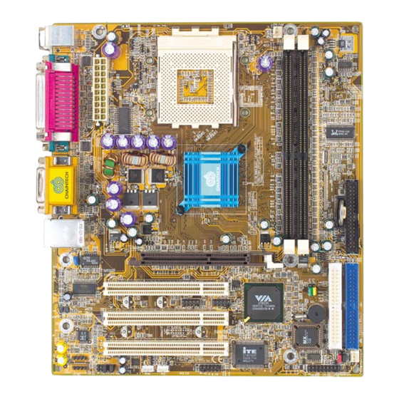
Chapter 1 Chapter 1 1-3 7VIL3 Motherboard Layout Introduction Chapter 1 1-1 Product Specifications Processor Page 6 Supports AMD Socket A Athlon XP/Athlon/Duron CPU Supports system clock at 200/266 MHz Page 4 Page 7 Chipset VIA KT266A + VT8235 Page 5... -
Page 4: Chapter 2 Hardware Setup
Chapter 2 Chapter 2 2-4 Connector and Jumper Settings Hardware Setup Chapter 2 Connectors are used to link the system board with other parts of the system, including the power supply, the keyboard, and the various controllers on the front panel of the system If your motherboard has already been installed in your computer you may still need to case. - Page 5 Chapter 2 Chapter 2 2. P-LED (Power LED Connector) screen. You must also set this jumper's cap to pins 2-3 to use this function. The power indicator LED shows the system's power status. It is important to pay attention to the correct cables and pin orientation (i.e., not to reverse the order of these JP23 (Green LED Mode) two connectors.) Definition...
-
Page 6: Chapter 3 Bios Setup Program
Chapter 2 Chapter 3 BIOS Setup Program Chapter 3 CN24 (Front Audio Connector) This connector give you the option of a front panel audio jack Phoenix-Award BIOS ROM has a built-in setup program that allows users to modify the cable ext. to be plug into a special custom designed system case. basic system configuration. -
Page 7: Advanced Bios Features
Chapter 3 Chapter 3 are using a VGA monitor; VGA BIOS will automatically configure this setting. pressed and held down. 3. Typematic Delay (Msec) Halt On The typematic delay sets how long after you press a key that a character begins When the system is powered on, BIOS performs a series of diagnostic tests called POST repeating. -
Page 8: Integrated Peripherals
Chapter 3 Chapter 3 DRAM Clock/Drive Control Video RAM Cacheable Enabling this function will allows caching of the video RAM, resulting in better system 1. DRAM Clock performance. However, if any programs write to this memory area, a system error may This selecting option allows you to control the DRAM speed. -
Page 9: Power Management Setup
Chapter 3 Chapter 3 below is displayed. This sample screen contains the manufacturer's default values for the IDE HDD Block Mode motherboard. Press [Enter] to enter the sub-menu, which contains the following items for advanced Block mode is also called block transfer, multiple commands, or multiple sector read/write. control: If your IDE hard drive supports block mode, select Enabled to auto-detect the optimal number of block read/writes per sector. -
Page 10: Pnp/Pci Configurations
Chapter 3 Chapter 3 Soft-Off by PWRBTN Resources Controlled By When set to Delay 4 Sec., this function allows the power button to put the system in When set to Manual the system BIOS will not refer to the ESCD for IRQ & DMA Suspend, a power saving mode. -
Page 11: Set Supervisor Password & User Password Setting
Chapter 3 Chapter 4 3-10 Set Supervisor Password & User Password Setting DRIVER Setup Chapter 4 There are four different variables that control password settings. The first two are located under the Security Option function in BIOS Features Setup Menu (Figure 3-1). Insert the support CD that come with your motherboard into your CD-ROM driver or When the Security Option function is set to Setup, a password is required to enter BIOS double-click the CD drive icon in [My computer] to open the setup screen. -
Page 12: Lan Driver Setup
Chapter 4 NOTE 4-3 LAN Driver Setup 1. Click [LAN Driver] 2. Please select [OK] to complete setup. NOTE 4-4 USB 2.0 Driver 1. Click [USB 2.0 Driver] 2. Click [Next >] to start software installation. All rights are reserved for the products and corporate names/logos that 3. - Page 13 How To Contact CHAINTECH How To Contact CHAINTECH Please do not hesitate to contact us if you have any problem about our products. Any opinion will be appreciated. For Asia, Africa, Australia and Pacific Island: For UK: CHAINTECH COMPUTER CO., LTD CHAINTECH UK., LTD.
Need help?
Do you have a question about the 7VIL3 and is the answer not in the manual?
Questions and answers