
Subscribe to Our Youtube Channel
Related Manuals for MRC 1425


Summary of Contents for MRC 1425
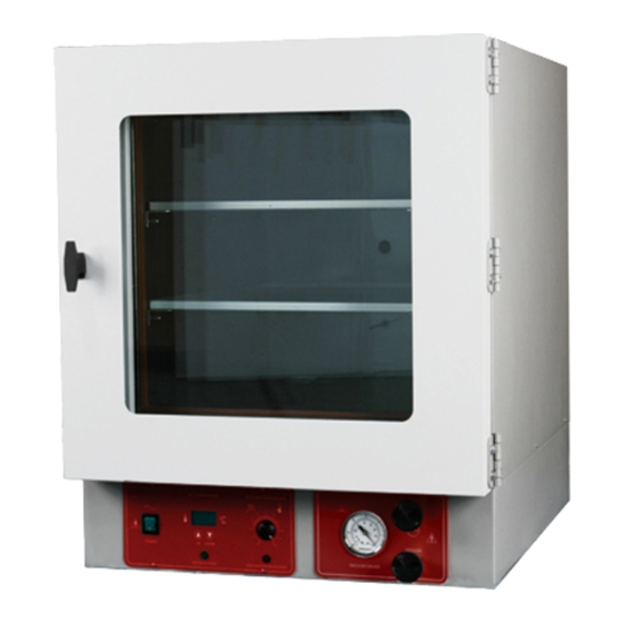
- Page 1 INSTRUCTION MANUAL FOR Vacuum Oven 1425/1445/1465 PLEASE READ THIS MANUAL CAREFULLY BEFORE OPERATION 3, Hagavish st. Israel 58817 Tel: 972 3 5595252, Fax: 972 3 5594529 mrc@mrclab.com MRC.VER.02-10.10...
-
Page 2: Table Of Contents
TABLE OF CONTENTS SECTION 1.0 RECEIVING AND INSPECTION SECTION 2.0 GRAPHIC SYMBOLS SECTION 3.0 INSTALLATION SECTION 4.0 PRECAUTIONS SECTION 5.0 CONTROL PANEL OVERVIEW SECTION 6.0 VACUUM OPERATION SECTION 7.0 OPERATION SECTION 8.0 MAINTENANCE SECTION 9.0 TROUBLESHOOTING SECTION 10.0 PARTS LIST UNIT SPECIFICATIONS SCHEMATICS These units are general purpose vacuum ovens for professional, industrial or educational... -
Page 3: Receiving And Inspection
Carefully check all packaging before discarding. The model 1425 is equipped with two (2) deep shelves and one (1) shallow shelf. The model 1445 is equipped with two (2) deep shelves, one (1) shallow shelf and four (4) adjustable feet. -
Page 4: Graphic Symbols
SECTION 2 GRAPHIC SYMBOLS Your oven has been provided with a display of graphic symbols which should help in identifying the use and function of the available user adjustable components. 2.1. Indicates "AC Power On". 2.2. Indicates "Manual Adjust". 2.3. Indicates “Temperature”. -
Page 5: Installation
Leveling: The unit must sit level and solidly. Model 1425 has four (4) rubber feet that are already attached to the unit and are not adjustable. Leveling feet are supplied with models 1445 and 1465 and must be installed in the four holes at the base of the unit. - Page 6 Cleaning: The oven was cleaned at the factory, but not sterilized. Remove all interior parts and clean the inside of the chamber, thoroughly with a solution that is appropriate for your application. DO NOT USE chlorine-based bleaches or abrasives as this will damage the stainless steel chamber. DO NOT USE spray cleaners that might leak through openings and cracks and get on electrical parts or that may contain solvents that will harm the coatings.
-
Page 7: Precautions
SECTION 4 PRECAUTIONS NOTE: THIS IS NOT AN EXPLOSION PROOF OVEN Do not place or use explosive, combustible, or flammable materials in the oven. Do not use sealed containers in the oven chamber. Do not cut or remove the ground prong, if present, from the power cord or use an ungrounded adapter plug. -
Page 8: Control Panel Overview
SECTION 5 CONTROL PANEL OVERVIEW (Figure 2) POWER SWITCH: This is the main power I/O (On/Off) switch. It must be in the ON position before any systems are operational. MAIN TEMPERATURE CONTROL: This is the Main Temperature control consisting of the digital display and UP/DOWN arrow pads for adjusting set point temperatures and calibration. - Page 9 Figure 2 1425 1445 & 1465...
-
Page 10: Vacuum Operation
SECTION 6 VACUUM OPERATION A pump with a pumping capacity four times greater than the chamber volume is commonly used. When working below vacuums of 1mm, a diffusion type pump will be needed. See Section 9.0 for chamber capacities IT IS IMPORTANT TO USE VACUUM TUBING FOR ALL THE VACUUM HOOKUPS. -
Page 11: Operation
SECTION 7 OPERATION Power Supply: Connect the service cord to a grounded outlet and switch unit to the ON position. If supplied with a detachable cord set, plug the female end into the inlet of the unit and the male end into the supply. Assure that units requiring a fuse have a fuse installed. - Page 12 When starting a new oven, allow the oven to operate two hours, or until it has started cycling normally before you begin using it. NOTE: Slight vapor or smoke may occur in the initial heat-up. This is the dissipation of protective coatings that have been added to the oven elements.
-
Page 13: Maintenance
SECTION 8 MAINTENANCE NOTE: Prior to any maintenance or service on this unit, disconnect the service cord from the power supply. Cleaning: Disinfect the oven interior on a regular basis. to prepare the oven for cleaning remove the shelves and door gasket. The shelves and door gasket are autoclavable. - Page 14 SECTION 9 TROUBLESHOOTING AND SERVICE TEMPERATURE Temperature too high 1/ controller set too high-see SECTION 6.4 2/ controller failed on – call Customer Service 3/ wiring error – call Customer Service Display reads "HI" or "400"+ probe is unplugged, is broken or wire to sensor is broken – trace wire from display to probe;...
- Page 15 check calibration – using independent thermometer, follow instructions in section 6.5 Unit will not heat up at all 1/ verify that controller is asking for heat by looking for Heating light – if pilot light is not on continuously during initial start up, there is a problem with the controller 2/ check amperage –...
- Page 16 operating correctly 4/ allow at least two hours to stabilize 5/ verify that reference thermometer is certified Can't adjust set points or calibration 1/ turn entire unit off and on to reset 2/ if repeatedly happens, call Customer Service Calibrated at one temperature, but not at another This can be a normal condition when operating temperature varies widely.
- Page 17 switch. Unit is smoking – Out of box This is not uncommon during initial operation. Put unit under vent and run at full power for one hour. Contamination in chamber 1/ see cleaning procedure in operator’s manual develop and follow standard operating procedure for specific application;...
-
Page 18: Parts List
3550521 1465 3550523 3550523 1425 700027 700027 Door Glass 1445 110107 110107 1465 3550586 3550586 1425 / 1445 9570741 9570786 Elements 1465 upper lower 9570740 9570740 1465 sides 9570729 9570729 EMI Filter, 10 AMP 2800502 3300502 Fuse, 10 AMP Fuse, 6.3 AMP - 250V... -
Page 19: Unit Specifications
UNIT SPECIFICATIONS Weight Shipping 1425 145 lbs. 105 lbs. 1445 220 lbs. 179 lbs. 1465 Exterior W x D x H Interior W x D x H Dimensions (in.) (in.) 1425 17 x 22.3 x 23.5 9 x 12 x 9 1445 20.5 x 28.2 x 26.25... - Page 20 WIRE DIAGRAM...
Need help?
Do you have a question about the 1425 and is the answer not in the manual?
Questions and answers