AAON Orion VCCX2 Technical Manual
Latest main controller updatable and customizable
Hide thumbs
Also See for Orion VCCX2:
- Technical manual (116 pages) ,
- Technical manual (140 pages) ,
- Technical manual (95 pages)
Table of Contents
Advertisement
Advertisement
Table of Contents

Related Manuals for AAON Orion VCCX2


Summary of Contents for AAON Orion VCCX2
- Page 1 VCCX2 Controller Technical Guide VCCX2 Controller Code: DT003800-001/SS1088 Version 1.02 and up Service Tool SD Code: DT001240-001/SS1063 Version 1.11 and up System Manager SD Code: DT002150-001/SS1068 Version 1.11 and up System Manager Touch Screen (Limited Access): DT004254-001/SS7013...
- Page 2 FL. EBTRON is a registered trademark of Ebtron, Inc., Loris, SC. ® It is the intent of AAON to provide accurate and current product GreenTrol is a registered trademark of GreenTrol Automation, Inc. information. However, in the interest of product improvement, AAON Loris, SC.
-
Page 3: Table Of Contents
TABLE OF CONTENTS OVERVIEW ..............................9 Features .................................. 9 Applications ................................10 Part Number Cross Reference ..........................11 Parts and Descriptions ............................12 VCCX2 Controller Components ..........................19 DIMENSIONS ............................20 VCCX2 Controller ..............................20 Refrigerant System Module ..........................21 VCC-X EM1 Expansion Module ..........................22 12 Relay E-BUS Module ............................ - Page 4 TABLE OF CONTENTS RSMV-HP Inputs ..............................53 RSMV-HP Outputs ..............................54 RSMD Inputs ................................. 55 RSMD Outputs ..............................56 RSMZ Inputs ................................. 57 RSMZ Outputs ..............................58 Subcool Monitor Module ............................59 MHGRV-X ................................60 MODGAS-X ................................61 MODGAS-XWR2 ..............................62 PREHEAT-X and PREHEAT-X-EXT ........................
- Page 5 TABLE OF CONTENTS Mechanical Failure and Failure Mode Alarms ....................... 91 Title 24 Economizer Alarms ..........................92 VCCX2 Controller Trend Logs ..........................93 RSMV/RSMD/RSMZ Trend Logs .......................... 94 RSMZ Trend Logs and Trend Log Enumerated Values ..................95 RSMZ Trend Logs ..............................96 Trend Log Bit String Decoding ..........................
- Page 6 FIGURES FIGURES Figure 1: VCCX2 Controller Components ......................19 Figure 2: VCCX2 Controller Dimensions .........................20 Figure 3: Typical Refrigerant System Module Dimensions (RSMV Shown) ............21 Figure 4: VCC-X EM1 Expansion Module Dimensions ...................22 Figure 5: 12 Relay E-BUS Module Dimensions ......................23 Figure 6: VCCX2 Controller Input Wiring ........................25 Figure 7: VCCX2 Controller Output Wiring ......................26 Figure 8: E-BUS Digital Room Sensor Wiring ......................27...
- Page 7 FIGURES Figure 41: MHGRV-X to VCCX2 Controller Wiring ....................60 Figure 42: MODGAS-X to VCCX2 Controller Wiring ....................61 Figure 43: MODGAS-XWR2 to VCCX2 Controller Wiring ..................62 Figure 44: PREHEAT-X to VCCX2 Module Wiring ....................63 Figure 45: Operator Interfaces ..........................64 Figure 46: VCCX2 Controller LED Locations ......................100 Figure 47: VCC-X EM1 Expansion Module LED Locations ..................100 Figure 48: Typical Stand-Alone System Layout ......................104 Figure 49: Typical Networked Single Loop System Layout ..................105...
- Page 8 TABLES TABLES Table 1: Voltage and Environment Requirements ....................24 Table 2: VCCX2 Controller Inputs and Outputs ....................65 Table 3: VCC-X EM1 Inputs and Outputs ......................65 Table 4: User-Configurable Relay Outputs ......................69 Table 5: VCCX2 Controller Trend Logs ........................93 Table 6: RSMZ Module Trend Logs ........................
-
Page 9: Overview
BACnet configuration. • Airflow control of outdoor air damper The VCCX2 Controller can communicate with all of AAON’s • Single zone VAV control with optional CAV heating Refrigerant System Modules (RSM). In addition, the VCC-X EM1 Expansion Module and 12 Relay E-BUS Expansion Module •... -
Page 10: Applications
Temperature and Humidity Sensors as the controlling sensors. Space Temperature (and Humidity) Sensors to accomplish this application. AAON Return Air Bypass Control provides improved moisture removal capabilities while utilizing internal space loads for Single Zone Variable Air Volume reheat by redirecting return air from the upstream side of the... -
Page 11: Part Number Cross Reference
OVERVIEW Part Number Cross Reference PART DESCRIPTION ORION AAON VCCX2 Controller OE338-26B-VCCX2 ASM01698 VCC-X EM1 Expansion Module OE336-23-VCCXEM1 ASM01691 Refrigerant System Module for VFD Compressors OE370-26-RSMV ASM01686 Refrigerant System Module VFD Compressors - Heat Pump OE370-26-RSMV-HP ASM01693 Refrigerant System Module for Digital Compressors... -
Page 12: Parts And Descriptions
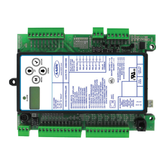
OVERVIEW Parts and Descriptions PART NO. PART DESCRIPTION ILLUSTRATION PAGE NO. ASM01698 VCCX2 Controller The VCCX2 Controller provides eight analog inputs, four analog outputs, eight binary inputs, and eight relay outputs. It also has an on-board BACnet port for connection to an MS/TP network. The Controller contains a 2 x 8 LCD character display and four buttons that allow for status and alarm display as well as Pages BACnet configuration. - Page 13 Temperature Setpoint. The PREHEAT-X-EXT module has an extended Leaving Air Temperature Setpoint minimum of 0°F and should only be used with the approval of AAON. The module directly connects to the VCCX2 Controller or indirectly using an E-BUS Expansion Board via an E-BUS cable.
- Page 14 OVERVIEW Parts and Descriptions PART NO. PART DESCRIPTION ILLUSTRATION PAGE NO. ASM01873 12 Relay E-BUS Expansion Module The 12 Relay Expansion Module adds 12 configurable relays to the VCCX2 Control System. It connects to the VCCX2 Controller with an E-BUS cable. Pages 23, 49 ASM02227...
- Page 15 OVERVIEW Parts and Descriptions PART NO. PART DESCRIPTION ILLUSTRATION PAGE NO. ASM01840 E-BUS Return Air Temperature and Humidity Sensor Used for return air temperature and humidity sensing applications. Connects to VCCX2 Controller or E-BUS Adapter Hub using E-BUS cable. Page 37 Includes: E-BUS Return Air Temperature and Humidity Sensor, mounted in a weatherproof handy box attached with a 3 ft.
- Page 16 When System Manager is to be mounted on a solid wall (concrete), Operator STATUS AAON recommends attaching the System Manager to a standard handy box. Interfaces SETPOINTS Includes: Modular System Manager SD with 4 GB SD card and 12 ft. pigtail...
- Page 17 The E-BUS Return Air Temperature and Humidity Sensor Emulator Board allows the use of third-party analog return air temperature and humidity sensors to emulate the AAON E-BUS Return Air Temperature and Humidity Sensor. Includes: E-BUS Sensor Emulator Board and 1.5 ft. E-BUS cable.
- Page 18 These schedules can also be configured to broadcast to other AAON HVAC equipment installed on the control system loop. Includes: GPC-XP Controller.
-
Page 19: Vccx2 Controller Components
OVERVIEW VCCX2 Controller Components Figure 1: VCCX2 Controller Components VCCX2 Controller Technical Guide... -
Page 20: Dimensions
DIMENSIONS VCCX2 Controller 6.04 2.75 0.213 8.38 7.95 4.10 Note: All Dimensions are in inches. 0.70 Note: Depth is 1.50 inches. Figure 2: VCCX2 Controller Dimensions VCCX2 Controller Technical Guide... -
Page 21: Refrigerant System Module
Refrigerant System Module 5.73 5.24 2.62 ALARM MENU ENTER DOWN RSM FOR VFD COMPRESSORS www.aaon.com AAON P/N: ASM01686 5.63 5.00 RELAY OUTPUTS RELAY CONTACT SUCTION PRESSURE SENSOR COMP 1 RATING IS 1 AMP +5 V MAX @ 24 VAC COMP 2... -
Page 22: Vcc-X Em1 Expansion Module
DIMENSIONS VCC-X EM1 Expansion Module 5.83 5.34 2.67 YS102482 REV1 4992 1002 10uF STATIC PRESSURE 1002 1002 10uF 1002 1002 10uF 1002 1002 3650 10uF 3650 ALARM TEMP SENSOR INPUTS 3650 STAT VREF 3650 COMM 5.63 5.00 1004 SIG1 1002 10uF AOUT1 EXH. -
Page 23: 12 Relay E-Bus Module
DIMENSIONS 12 Relay E-BUS Module 6.06 5.52 2.76 MADE IN USA SERIAL # RLY-COM RLY-COM RLY1 RLY9 RLY2 RLY10 RLY3 RLY11 RLY4 RLY12 ADDRESS 5.00 5.63 RLY-COM RLY5 RLY6 RLY7 RLY8 R214 R212 R211 RELAY R213 TB10 EXPANSION BOARD YS102324 REV 2 24VAC 1002 0.20... -
Page 24: Wiring
In general, most VCCX2 Controllers are installed and wired at be maintained between the boards. Failure the AAON factory. It is also possible to purchase these controllers to observe correct polarity will result in through a local AAON representative for installation in the field. -
Page 25: Vccx2 Controller Inputs
WIRING VCCX2 Controller Inputs VCCX2 Controller Inputs The VCCX2 Controller is designed with eight analog inputs, four analog outputs, eight binary inputs and eight relay outputs. There are also two E-BUS expansion ports which allow the use of communicating sensors and E-BUS modules. See Figure 6, this page, and Figure 7, page 26, for wiring details. -
Page 26: Vccx2 Controller Outputs
WIRING VCCX2 Controller Outputs Note: All Relay Outputs are normally open and rated for 24 VAC power only. 1 amp maximum load Waterside Economizer Valve Figure 7: VCCX2 Controller Output Wiring VCCX2 Controller Technical Guide... -
Page 27: E-Bus Digital Room Sensor
WIRING E-BUS Digital Room Sensor E-BUS Digital Room Sensor The E-BUS Digital Room Sensor should be mounted on the wall in an area that does not have drafts or is exposed to direct The ASM01819 E-BUS Digital Room Sensor can be used to sunlight. -
Page 28: Wall-Mounted E-Bus Co
WIRING Wall-Mounted E-BUS CO Sensor Wall-Mounted E-BUS CO Sensor A Duct-Mounted E-BUS CO Sensor can be used, if desired, instead of the Wall-Mounted E-BUS CO Sensor. See Figure 10, The ASM01829 Wall-Mounted E-BUS CO Sensor is used to page 29, for Duct-Mounted E-BUS CO Sensor wiring details. -
Page 29: Duct-Mounted E-Bus Co
The Duct-Mounted E-BUS CO Sensor is comprised of the Sensor, the AAON Aspiration Box Assembly, and a remote pickup tube. Note: The Duct-Mounted E-BUS CO Sensor connects to the VCCX2 Controller using an E-BUS cable of the required length or the provided 10 ft. -
Page 30: Space Temperature Sensor
WIRING Space Temperature Sensor Space Temperature Sensor The Space Temperature Sensor is available as a sensor only, sensor with override button, sensor with slide adjust, and sensor The ASM02227, ASM01638, ASM01642, ASM01643 Space with slide adjust and override configurations. Temperature Sensor is typically used for CAV HVAC unit A space temperature signal can be connected to Analog Input 1 applications controlling one zone. -
Page 31: Supply Air Temperature Sensor
WIRING Supply Air Temperature Sensor Supply Air Temperature Sensor A supply air temperature signal can be connected to AI3 for applications requiring a Supply Air Temperature Setpoint. The G051240 (6 inch) or G051250 (12 inch) Supply Air See Figure 12, this page, for details. Temperature Sensor must be wired as shown for proper operation. -
Page 32: Return Air Temperature Sensor
WIRING Return Air Temperature Sensor Return Air Temperature Sensor A return air temperature signal can be connected to AI4 for applications requiring a Return Air Temperature Setpoint. G051240 (6 inch) or G051250 (12 inch) Return Air Temperature See Figure 13, this page, for details. Sensor must be wired as shown for proper operation. -
Page 33: Building Pressure Sensor
WIRING Building Pressure Sensor Building Pressure Sensor It is very important to be certain that all WARNING: wiring is correct as shown in the wiring The ASM01832 Building Pressure Sensor must be wired diagram below. Failure to observe the as shown in Figure 14, this page. There are three terminal correct polarity will result in damage to the connections on the Building Pressure Sensor. -
Page 34: Remote Supply Air Temperature Reset
WIRING Remote Supply Air Temperature Reset Remote Supply Air Temperature Reset Signal A remote supply air temperature reset signal can be connected to AI6 for applications requiring remote reset of the Supply Air Temperature Setpoint. See Figure 15, this page. Figure 15: Remote SAT Reset Signal Wiring VCCX2 Controller Technical Guide... -
Page 35: E-Bus Outdoor Air Temperature Sensor
WIRING E-BUS Outdoor Air Temperature Sensor Outdoor Air Temperature Sensor Be sure to mount the sensor in the upright CAUTION: position, in an area that is not exposed to direct The G042330 Outdoor Air Temperature Sensor must be wired sunlight, and is protected from the elements. as shown for proper operation of the VCCX2 Controller. -
Page 36: E-Bus Outdoor Air Temperature And Humidity Sensor
WIRING E-BUS Outdoor Air Temperature and Humidity Sensor E-BUS Horizontal or Vertical Outdoor Air Be sure to mount the sensor in the upright CAUTION: Temperature and Humidity Sensor position, in an area that is not exposed to direct sunlight, and is protected from the elements. The ASM01836 (Horizontal) or ASM01838 (Vertical) E-BUS The shaded area under the HVAC unit rain Outdoor Air Temperature and Humidity Sensor connects to the... -
Page 37: E-Bus Return Air Temperature And Humidity Sensor
WIRING E-BUS Return Air Temperature and Humidity Sensor E-BUS Return Air Temperature Be sure to mount the sensor in the upright CAUTION: and Humidity Sensor position, in an area that is not exposed to direct sunlight, and is protected from the elements. The ASM01840 E-BUS Return Air Temperature and Humidity The shaded area under the HVAC unit rain Sensor connects to the VCCX2 Controller. -
Page 38: Duct Static Pressure Transducer
WIRING Duct Static Pressure Transducer Duct Static Pressure Transducer AAON strongly recommends using pneumatic CAUTION: tubing instead of relocating the sensor. The ASM01640 Duct Static Pressure Transducer plugs directly Extending the wires could cause voltage drop into the VCCX2 Controller’s static pressure port. The Duct Static problems. -
Page 39: Supply Fan Vfd Or Bypass Damper Actuator
WIRING Supply Fan VFD or Bypass Damper Actuator Supply Fan VFD Signal VFD units can cause large transient noise CAUTION: or Bypass Damper Actuator spikes which can cause interference to be propagated on other electronic equipment. Use The Supply Fan VFD Signal is a user-adjustable signal with a shielded wire wherever possible and route all range of 0-10 VDC from Analog Output 1 (AO1) on the VCCX2 sensor and controller wiring away from the... -
Page 40: Economizer Damper Actuator Or Waterside Economizer Actuator
WIRING Economizer Damper Actuator or Waterside Economizer Actuator Economizer Damper Actuator Waterside Economizer Valve The economizer damper actuator signal voltage output, using The waterside economizer valve must be wired as shown in AO2 is user-adjustable, but must be set to 2-10 VDC for this Figure 21, this page, for proper operation. -
Page 41: Modulating Heating Device
WIRING Modulating Heating Device Modulating Heating Device It is very important to be certain that all WARNING: wiring is correct as shown in the wiring The Modulating Heating Device signal voltage output is a user- diagram below. Failure to observe the adjustable signal with a range of 0-10 VDC from AO3 when correct polarity could result in damage programming the controller. -
Page 42: Building Pressure Control Outputs
WIRING Building Pressure Control Outputs Building Pressure Control Output When using the outdside air damper for reverse building pressure control, the output signal must be configured for reverse acting The Building Pressure Control Output is a 0-10 VDC or 2-10 operation. -
Page 43: Vcc-X Em1 Expansion Module
WIRING VCC-X EM1 Expansion Module VCC-X EM1 Expansion Module Return Air Plenum Pressure Sensor The VCC-X EM1 Expansion Module connects to the VCCX2 The ASM01832 Return Air Plenum Pressure Sensor (also used Controller with an E-BUS cable and adds an additional: five as a Building Static Pressure Sensor, as shown on page 33) analog inputs, five analog outputs, three binary inputs, and five must be wired as shown in Figure 24, this page. -
Page 44: Entering Water Temperature Sensor
WIRING Entering Water Temperature Sensor Secure sensor element and thermal mastic strip to pipe with supplied wire tie. Be sure to tighten wire tie snugly to ensure good thermal contact. Figure 25: Entering Water Temperature Sensor VCCX2 Controller Technical Guide... -
Page 45: Vcc-X Em1 Expansion Module Inputs
WIRING VCC-X EM1 Expansion Module Inputs Exhaust Duct Static Pressure Sensor Observe polarity! All boards must be wired WARNING: with GND-to-GND and 24 VAC-to-24 The ASM01640 Exhaust Duct Static Pressure Sensor plugs VAC. Failure to observe polarity will directly into the EM1’s static pressure port. The Duct Static result in damage to one or more of the Pressure Sensor reading is used to determine current exhaust duct boards. -
Page 46: Vcc-X Em1 Expansion Module Outputs
WIRING VCC-X EM1 Expansion Module Outputs VCC-X EM1 Expansion Module Outputs Observe polarity! All boards must be wired WARNING: with GND-to-GND and 24 VAC-to-24 The VCC-X EM1 Expansion Module must be connected to 24 VAC. Failure to observe polarity will VAC as shown in the wiring diagram below. -
Page 47: Modulating Cooling Output
VCC-X EM1 Expansion Module RELAY OUTPUT TERMINALS Chilled Water VCC-X E EXPANSION Valve Actuator AAON P/N: ASM01691 ANALOG OUTPUT TERMINALS CHILLED WATER RETURN DAMPER RETURN BYPASS EXH. DAMPER NOT USED NOT USED POWER INPUT TERMINAL BLOCK... -
Page 48: Return Air Bypass
Return Air Bypass Return Air Bypass Observe polarity! All boards must be wired WARNING: The VCCX2 Controller can be configured for AAON Return Air with GND-to-GND and 24 VAC-to-24 VAC. Failure to observe polarity will Bypass applications. These provide improved moisture removal... -
Page 49: 12 Relay E-Bus Expansion Module
WIRING 12 Relay E-BUS Expansion Module 12 Relay E-BUS Expansion Module Observe polarity! All boards must be wired WARNING: with GND-to-GND and 24 VAC-to-24 The ASM01873 12 Relay E-BUS Expansion Module provides VAC. Failure to observe polarity will for 12 dry contact configurable relay outputs. See Figure 30, result in damage to one or more of the this page, for complete wiring details. -
Page 50: Ebtron, Greentrol, And Paragon Digital Transmitters
VCCX2 Controller. No other series of the EBTRON, GreenTrol, or Paragon Airflow Measurement transmitters will work for this application. Contact AAON Controls for information on other airflow Digital Transmitter to the VCCX2 Control System. Wire the station options. -
Page 51: Rsmv Inputs
WIRING RSMV Inputs Refrigerant System Module • Modulates the condenser fan to maintain the Head Pressure Setpoint. for VFD Compressors • Modulates the expansion valves to maintain the The ASM01686 RSMV monitors and controls one tandem Superheat Setpoint. refrigeration circuit of the HVAC unit. The module is designed •... -
Page 52: Rsmv Outputs
WIRING RSMV Outputs Suction Pressure Transducer The Shraeder port used for installation of the CAUTION: Suction Pressure Transducer should be located The ASM02222 Suction Pressure Transducer must be wired as in a vertical position of the suction line to shown in Figure 32, page 51. It is required for all compressorized prevent refrigerant oil from accumulating in VCCX2 applications. -
Page 53: Rsmv-Hp Inputs
WIRING RSMV-HP Inputs Refrigerant System Module for VFD Observe polarity! All boards must be wired WARNING: Compressors - Heat Pump with GND-to-GND and 24 VAC-to-24 VAC. Failure to observe polarity will The ASM01693 RSMV-HP monitors and controls one result in damage to one or more of the refrigeration circuit of the HVAC unit. -
Page 54: Rsmv-Hp Outputs
WIRING RSMV-HP Outputs Coil Temperature Sensors The Shraeder port used for installation of the CAUTION: The Coil Temperature Sensors are used to measure coil Suction Pressure Transducer should be located temperature after each evaporator coil line. This temperature in a vertical position of the suction line to combined with the calculated saturated refrigerant temperature is prevent refrigerant oil from accumulating in used to calculate the superheat of each individual evaporator coil. -
Page 55: Rsmd Inputs
WIRING RSMD Inputs Refrigerant System Module for Digital The RSMD provides three analog inputs, four binary inputs, five relays, and two analog outputs. See Figure 36, this page, Compressors for inputs wiring and Figure 37, page 56, for outputs wiring. The ASM02201 RSMD can monitor and control up to two Suction Pressure Transducer compressors and condensers. -
Page 56: Rsmd Outputs
WIRING RSMD Outputs Head Pressure Control The Shraeder port used for installation of the CAUTION: The Head Pressure Transducers are used to measure head pressure Suction Pressure Transducer should be located at the discharge line. This head pressure is used to drive the in a vertical position of the suction line to condenser fans with a 0-10 VDC output signal to maintain a prevent refrigerant oil from accumulating in... -
Page 57: Rsmz Inputs
WIRING RSMZ Inputs RSMZ Inputs Wiring See Important Wiring Considerations, page 24, for power source requirements. When wiring the RSMZ Module, its relay The RSMZ monitors and controls one refrigeration circuit of outputs must be wired as wet contacts (connected to 24 VAC). the HVAC unit. -
Page 58: Rsmz Outputs
WIRING RSMZ Outputs RSMZ Outputs Wiring • Monitors the performance of the DMQ Universal Superheat Controller/Sensor to maintain the Superheat The RSMZ provides the following features: Setpoint of each evaporator coil. • Modulates the compressors to satisfy the suction coil •... -
Page 59: Subcool Monitor Module
WIRING Subcool Monitor Module Subcool Monitor Wiring The Subcool Monitor contains a 2 x 8 LCD character display and four buttons that allow for configuration, status, and alarm The ASM02350 Subcool Monitor reads the liquid line pressure display. This module must be configured to work with R410-A then converts it to the saturated liquid temperature and compares refrigerant and is configured for 667 psi liquid line pressure it to the measured liquid line temperature to calculate subcooling. -
Page 60: Mhgrv-X
WIRING MHGRV-X MHGRV-X Wiring The following information will be passed between the MHGRV-X and the VCCX2 Controller: The ASM01670 MHGRV-X is designed to control a modulating • Reheat enable command hot gas reheat valve to maintain a desired Supply Air Temperature •... -
Page 61: Modgas-X
WIRING MODGAS-X MODGAS-X Wiring The following information will be passed between the MODGAS-X and the VCCX2 Controller: The ASM01668 MODGAS-X is designed to modulate up to two • Heat activation command gas valves to maintain a desired discharge air temperature. It also •... -
Page 62: Modgas-Xwr2
AUX BIN RLY6 Fixed Heat Stage 4 HEAT EN COMMON DOWN RESET IN OPTIONS Proof of Ignition PO-IGN1 AAON P/N: ASM01695 Signal 1 (24 VAC) MODGAS-XWR2 www.aaon.com Modulating INPUT TERMINALS (TYPE) RELAY AUX AIN OUTPUTS LOW SPEED Gas Valve 1... -
Page 63: Preheat-X And Preheat-X-Ext
Leaving Air Temperature Setpoint. The PREHEAT-X-EXT has • Entering air temperature status an extended Leaving Air Temperature Setpoint minimum of 0°F. It should only be used with the approval of AAON. • Alarm status • If the communication is interrupted between the... -
Page 64: Start-Up And Commissioning
System Manager TS-L Technical Guide. In order to have a trouble free start-up, it is important to follow a No matter which operator interface is used, AAON recommends few simple procedures. Before applying power for the first time, proceeding with the programming and setup of the VCCX2 it is very important to run through a few simple checks. -
Page 65: Inputs And Outputs
INPUTS AND OUTPUTS VCCX2 Controller and EM1 Module Input/Output Maps Input/Output Map VCCX2 CONTROLLER Analog Inputs (AI) See Table 2, this page, for VCCX2 Controller inputs and outputs Space Temperature (AI1) and Table 3, this page, for VCC-X EM1 inputs and outputs. For the RSM Module and Evaporative Condenser input and output Space Slide Adjust (AI2) tables, please see the individual Technical Guides. -
Page 66: Vccx2 Controller Inputs
INPUTS AND OUTPUTS VCCX2 Controller Inputs VCCX2 Controller Inputs exhaust fan output that activates the exhaust fan any time the building pressure is above the Building Pressure Setpoint. AI1 - Space Temperature Sensor Input AI6 - Remote Supply Air Temperature Reset Signal The Space Temperature Sensor will initiate Occupied Heating If a remote supply air temperature reset signal is configured as and Cooling Modes if the unit is configured for space temperature... -
Page 67: Vccx2 Controller Outputs
INPUTS AND OUTPUTS VCCX2 Controller Outputs VCCX2 Controller Outputs BI3 - Hood On/Off Input When this wet contact input closes (hood on), the VCCX2 AO1 - Main Supply Fan VFD Control Signal or Controller switches from indoor air control to outdoor air control. Bypass Damper Control Signal This is typically used on CAV applications requiring CAV/MUA This user-adjustable voltage signal is used to modulate the supply... -
Page 68: Vcc-X Em1 Expansion Module
RLY2-RLY8 - User-Configurable Relays is used to modulate a return air damper actuator in conjunction with a Return Air Bypass Damper actuator for AAON Precise These relays are configurable by the user. For all the available Air Control or Digital Precise Air Control applications. -
Page 69: 12 Relay E-Bus Expansion Module
INPUTS AND OUTPUTS 12 Relay E-BUS Expansion Module Relay Description Details Cooling Stage Configured for each fixed stage of cooling (except heat pump compressor). Heating Stage Configured for each fixed stage of heating. Aux Heat Configured for a fixed stage of aux heat in a heat pump unit. Emergency Heat Configured for a fixed stage emergency heat in a heat pump unit. -
Page 70: Sequence Of Operations
SEQUENCE OF OPERATIONS Supply Fan Operation and HVAC Source Configuration Options Supply Fan Operation HVAC Source Configuration Options Any time the supply fan is requested to start, a one-minute The VCCX2 Controller can be configured to have various minimum off timer must be satisfied. If the timer is satisfied, the HVAC source options that will determine the mode of operation supply fan relay is activated while all other outputs are held off (Heating, Cooling, or Vent Mode) of the unit. -
Page 71: Occupied/Unoccupied Operation And Hvac Modes Of Operation
SEQUENCE OF OPERATIONS Occupied/Unoccupied Operation and HVAC Modes of Operation Occupied/Unoccupied Mode of Operation HVAC Modes of Operation The VCCX2 Controller can utilize several methods for There are eight possible HVAC Modes of Operation. They are determining the Occupied Mode of Operation. These are as as follows: follows: •... -
Page 72: Cooling Mode
SEQUENCE OF OPERATIONS Cooling Mode Cooling Mode Staged Cooling without the Refrigerant System Modules Occupied Cooling is enabled when the temperature at the Mode An RSM will not be used on units with fixed stage compressors Enable Sensor rises one deadband above the Cooling Setpoint. that are not doing dehumidification and that do not require head Cooling is disabled when the mode enable temperature falls one pressure control, or on units with on/off chilled water. -
Page 73: Economizer Operation
SEQUENCE OF OPERATIONS Economizer Operation Economizer Operation (Standard) Economizer Override Via BACnet As stated above, the economizer must reach and remain at 100% For Waterside Economizer Operation, see page NOTE: before compressors will be allowed to stage on to meet the Cooling Supply Air Setpoint. -
Page 74: Dehumidification Mode
SEQUENCE OF OPERATIONS Dehumidification Mode Dehumidification Mode Do not use this option on a MUA unit that does NOTE: On VAV, CAV, single VAV, and high percentage outdoor units not have return air and which is not configured for with space temperature control, the Dehumidification Mode space controlled night setback operation. -
Page 75: Reheat, Coil Suction, And Return Air Bypass Damper Control
Setpoint. If less air needs to pass through the Return Air Bypass Cooling application if a Special Purchase Damper, enter a smaller number in the Return Air Damper Factor Authorization is not obtained from the Setpoint. AAON Factory at the time the HVAC unit is ordered. VCCX2 Controller Technical Guide... -
Page 76: Heating Mode
SEQUENCE OF OPERATIONS Heating Mode Heating Mode The minimum signal adjustment per time period is based on the modulating heating proportional window. The larger the Available heating options are staged gas, modulating gas, staged modulating heating proportional window, the smaller the signal electric, on/off hot water, modulating hot water, and modulating adjustment will be per time period. -
Page 77: Ventilation Mode, Remote Contact Control, And Space Sensor Operation
SEQUENCE OF OPERATIONS Ventilation Mode, Remote Contact Control, and Space Sensor Operation If both the forced heating and forced cooling inputs are inactive Primary Modulating Heat with Secondary Staged Heat or if both are simultaneously active, then the unit is in Vent Mode state. -
Page 78: Indoor Air Quality And Morning Mode Operations
SEQUENCE OF OPERATIONS Indoor Air Quality and Morning Mode Operations Indoor Air Quality (CO ) Control Operation If stand-alone VAV boxes that need to be forced wide open during the Warm-Up Mode, configure one of the relay outputs to be used If the VCCX2 Controller is configured to monitor and control during this Mode. -
Page 79: Single Zone Variable Air Volume
SEQUENCE OF OPERATIONS Single Zone Variable Air Volume Single Zone Variable Air Volume When the controller is in the Vent-Dehumidification Mode, the supply fan VFD will still modulate based on the space Single zone VAV is an application where the supply fan VFD temperature. -
Page 80: Supply Air Temperature, Airflow Monitoring, And Preheater Operation
Supply Air Temperature Setpoints.” The following reset source in conjunction with a GreenTrol GF series of airflow station. options are available in this release: Contact AAON Controls for information on other airflow station options. The VCCX2 will control the outdoor air damper to • Space temperature maintain an Outdoor Air Cubic Foot per Minute Setpoint. -
Page 81: Low Ambient Operation, Heat Wheel, And Duct Static Pressure Control
SEQUENCE OF OPERATIONS Low Ambient Operation, Heat Wheel, and Duct Static Pressure Control Low Ambient Operation Duct Static Pressure Control A low ambient relay can be configured. Whenever the outdoor If the VCCX2 Controller has been configured for duct static air temperature falls below the Low Ambient Setpoint, this low pressure control, then anytime the supply fan is operating, the ambient relay will energize. -
Page 82: Duct Static Setpoint Reset, Building Pressure Control
Exhaust Fan VFD or Modulating Exhaust Damper: If configured for modulating exhaust, a user-adjustable If the VCCX2 Controller is being used with AAON VAV box voltage output (AO4 – Building Pressure Output) will controllers in a VAV system, the Duct Static Pressure Setpoint can be used to control this fan or damper. -
Page 83: Exhaust Duct Static Pressure Control
SEQUENCE OF OPERATIONS Exhaust Duct Static Pressure Control Return Plenum Pressure Control The VCCX2 Controller can control the return plenum pressure using a motorized exhaust damper. This is used on certain RNZ units that have a return fan that will be used to control building static pressure. -
Page 84: Make-Up Air, Dual Mode, And Space Temperature Control
SEQUENCE OF OPERATIONS Make-up Air, Dual Mode, and Space Temperature Control Make-up Air Operation Space Temperature Control of High Percentage Outdoor Air Units The VCCX2 will use the normal Cooling and Occupied Mode: Heating Mode Enable Setpoints (not the Hood On Setpoints) This option allows for space temperature control of 100% in conjunction with the Outdoor Air Temperature Sensor to outdoor air units or units with a high percentage of outdoor air... -
Page 85: Variable Air Volume With Supply Air Tempering And Air To Air Heat Pump
SEQUENCE OF OPERATIONS Variable Air Volume with Supply Air Tempering and Air to Air Heat Pump Variable Air Volume Operation with Supply In this operation, if night setback operation will be initiated by a Space Sensor connected to the VCCX2 Controller, then the Air Tempering (Variable Air Volume night setback Cooling and Heating offsets will be applied to the Operation with Outdoor Air Temperature... -
Page 86: Heat Pump Standard Defrost, Adaptive Defrost, And Water Source Heat Pump
SEQUENCE OF OPERATIONS Heat Pump Standard Defrost, Adaptive Defrost, and Water Source Heat Pump Heat Pump Standard Defrost Operation Water Source Heat Pump Operation If using the VCCX2 Controller with an installed defrost coil A reversing valve relay output can be configured to activate with temperature switch, a defrost cycle is available. -
Page 87: Electronic Expansion Valve Operation, Head Pressure, And Evaporative Condenser
SEQUENCE OF OPERATIONS Electronic Expansion Valve Operation, Head Pressure, and Evaporative Condenser, Electronic Expansion Valve Operation Evaporative Condenser Operation If using electronic expansion valves with Bitzer VFD Compressors If the unit has been configured for evaporative condenser control and the RSMV Module, then a coil (suction line) temperature and the outdoor air temperature is above the Evaporative/ sensor will measure the coil (suction line) temperature after each Modulating Condenser Low Ambient Setpoint, the evaporative... -
Page 88: Waterside Economizer, Temperature Protection, And Outdoor Air Lockouts
SEQUENCE OF OPERATIONS Waterside Economizer, Temperature Protection, and Outdoor Air Lockouts Waterside Economizer Operation Temperature Protection If the unit is equipped with a waterside economizer, the following Temperature protection is activated when the supply air describes the operation of the waterside economizer valve, the temperature rises above the high cutoff temperature (immediate) waterside economizer bypass valve, and the condenser valve or drops below the low cutoff temperature (for 10 minutes). -
Page 89: System Broadcasts And Alarm Detection
SEQUENCE OF OPERATIONS System Broadcasts and Alarm Detection System Broadcasts • Preheat Low Temperature • Missing RSM #1 The VCCX2 Controller can be configured to broadcast building • Missing RSM #2 pressure, outdoor air temperature, outdoor air humidity, space temperature, space humidity, and CO to any VCCX2 Controller •... -
Page 90: Sensor Failure Alarms
SEQUENCE OF OPERATIONS Sensor Failure Alarms Sensor Failure Alarms Airflow Alarms • Outdoor Airflow Sensor Alarm Supply Air Temperature Sensor Failure Alarm • Supply Airflow Sensor Alarm The Supply Air Temperature Sensor failure alarm is generated • Return Airflow Sensor Alarm when the controller detects an open or short circuit on the Supply Air Temperature Sensor input. -
Page 91: Mechanical Failure And Failure Mode Alarms
SEQUENCE OF OPERATIONS Mechanical Failure and Failure Mode Alarms Mechanical Failure Alarms Dirty Filter Alarm A differential pressure switch is used to provide a 24 VAC wet Mechanical Cooling Failure contact closure to indicate a dirty filter status. A dirty filter alarm The mechanical cooling failure alarm is is then generated. -
Page 92: Title 24 Economizer Alarms
SEQUENCE OF OPERATIONS Title 24 Economizer Alarms Failure Mode Alarms Title 24 (FDD) Economizer Alarms High and Low Supply Air Temperature Alarms Economizer Temperature Sensor Failure If the supply air temperature rises above the user-adjustable Outside air or Supply Air Temperature Sensor is shorted or High Supply Air Temperature Cutoff Setpoint, heating will be missing. -
Page 93: Vccx2 Controller Trend Logs
SEQUENCE OF OPERATIONS VCCX2 Controller Trend Logs VCCX2 CONTROLLER TREND LOGS Item Description Log Abbreviation (Unit) Date Date (Day Month) Time Time (24 Hr.) Mode of Operation Mode (Enumerated)* HVAC Mode HVAC (Enumerated)* Space Temperature Space (ºF) Indoor Humidity InRH (%) Mode Cooling Setpoint CSP (ºF) Mode Heating Setpoint... -
Page 94: Rsmv/Rsmd/Rsmz Trend Logs
SEQUENCE OF OPERATIONS RSMV/RSMD/RSMZ Trend Logs RSM Trend Logs RSMV / RSMD MODULE TREND LOGS (TYPICAL OF 4 RSM MODULES) There can be as many as four RSMVs, four RSMDs, or six Item Description Log Abbreviation (Unit) RSMZs on a unit, with each RSM controlling up to two compressors and condensers. -
Page 95: Rsmz Trend Logs And Trend Log Enumerated Values
SEQUENCE OF OPERATIONS RSMZ Trend Logs and Trend Log Enumerated Values TREND LOG ENUMERATED VALUES RSMZ TREND LOG BIT STRINGS - RSM ALARMS Item Description Value Description Item Bit Value Description Unoccupied LowSuction Mode Occupied UnsafeSuction Push Button Override Active TripHighDiscPSI_Comp1 Compressor1_NotRunning Vent Mode... -
Page 96: Rsmz Trend Logs
SEQUENCE OF OPERATIONS RSMZ Trend Logs RSMZ TREND LOG BIT STRINGS - VFD STATUS Item Value VFD Status (Bit = 0) VFD Status (Bit = 1) 0 = Control Not Ready 1 = Control Ready 0 = Drive Not Ready 1= Drive Ready 0 = Coasting 1 = Enable... -
Page 97: Trend Log Bit String Decoding
SEQUENCE OF OPERATIONS Trend Log Bit String Decoding Trend Log Bit String Decoding Example 2 With a value of 86, start with 64 (Remote Dehumidification). Bit string values allow the manipulation of binary data in useful This would have left a remainder of 22 (86 – 64 = 22). Then ways. -
Page 98: Trend Log Bit String Decoding
SEQUENCE OF OPERATIONS Trend Log Bit String Decoding VCCX2 TREND LOG BIT STRINGS Item Value Description Item Value Description Bad Supply Sensor Fan Proving Bad Return Sensor Dirty Filter Bad Outdoor Air Sensor Hood On/Off Bad Space Sensor Remote Occupied Bin IN Bad CO2 Sensor Remote Cooling... -
Page 99: Troubleshooting
TROUBLESHOOTING VCCX2 Controller and EM1 LED Diagnostics VCCX2 Controller LEDs RLY2 - RLY8 - These green LEDs lights up when the relays are enabled and stays lit as long as they are active. The VCCX2 Controller is equipped with LEDs that can be used Binary Input LEDs to verify operation and perform troubleshooting. -
Page 100: Figure 46: Vccx2 Controller Led Locations
TROUBLESHOOTING VCCX2 Controller and EM1 LED Diagnostics Figure 46: VCCX2 Controller LED Locations Figure 47: VCC-X EM1 Expansion Module LED Locations VCCX2 Controller Technical Guide... -
Page 101: Temperature Sensor Testing
TROUBLESHOOTING Temperature Sensor Testing Space, Supply Air, Outdoor Air Thermistor Sensor Testing Instructions or Return Air Temperature Sensor Testing Use the resistance column to check the Thermistor Sensor while disconnected from the controllers (not powered). The following sensor voltage and resistance table is provided to Use the voltage column to check sensors while connected to aid in checking sensors that appear to be operating incorrectly. -
Page 102: Duct Static Pressure And Building Pressure Sensor Testing
TROUBLESHOOTING Duct Static Pressure and Building Pressure Sensor Testing Duct Static Pressure Sensor Building Pressure Sensor Testing Instructions Testing Instructions Use the voltage column, Table 16, this page, to check the Duct Use the voltage column, Table 17, this page, to check the Static Pressure Sensor while connected to powered controllers. -
Page 103: Appendix A - System Configuration
VCCX2 Controllers. With this system, connect the controllers 3,500 controllers to be networked. together using AAON communications wire or 18-gauge, two- conductor, twisted pair with shield wire (Belden #82760 or See Figure 50, page 106, for a typical networked multiple loop equivalent). -
Page 104: Stand-Alone System Layout
APPENDIX A - SYSTEM CONFIGURATION Stand-Alone System Layout Figure 48: Typical Stand-Alone System Layout VCCX2 Controller Technical Guide... -
Page 105: Networked System Single Loop Layout
APPENDIX A - SYSTEM CONFIGURATION Networked System Single Loop Layout 1002 .1uF .1uF .1uF .1uF .1uF .1uF .1uF .1uF 1002 .1uF .1uF .1uF .1uF .1uF .1uF 1002 .1uF .1uF .1uF .1uF Figure 49: Typical Networked Single Loop System Layout VCCX2 Controller Technical Guide... -
Page 106: Networked System Multiple Loop Layout
APPENDIX A - SYSTEM CONFIGURATION Networked System Multiple Loop Layout 1002 .1uF .1uF .1uF .1uF .1uF .1uF .1uF .1uF 1002 .1uF .1uF .1uF .1uF .1uF .1uF 1002 .1uF .1uF .1uF .1uF SERIAL # SERIAL # .1uF .1uF PD DRV PD DRV LOOP DRV 1002 1002... -
Page 107: Appendix B - Vccx2 Lcd Screens
APPENDIX B - VCCX2 LCD SCREENS Navigation Keys LCD Display Screen and Navigation Keys Navigation Key Function The LCD display screens and buttons allow display status and MENU Use the MENU key to move through screens alarms, enable force modes, and make BACnet configuration within Main Menu categories and return to the changes. -
Page 108: Main Screens Map
Status screen. Press to go to the Factory Test Mode screen. STATUS FACTTEST MODE NOTE: This screen is for AAON factory use only. Press to scroll through the Status screens. Press to return to the first Main Menu screen. Press to go to the Alarms screen. -
Page 109: Setting Screens
APPENDIX B - VCCX2 LCD SCREENS Setting Screens Settings Screens DEVICEID Refer to the following map when navigating through the Settings XXXXXXX screens. From the Settings screen, press <ENTER> to scroll through the screens. BACnet - CURRENT DEVICE ID A Device ID of up to 7 digits can be entered. The <ENTER>... -
Page 110: Status Screens
APPENDIX B - VCCX2 LCD SCREENS Status Screens Status Screens SPC RH Refer to the following map when navigating through the Status X.X % screens. From the Status Screen, press <ENTER> to scroll through the screens. SPACE HUMIDITY 0.00% - 100% STATUS SAT TEMP XX.X... -
Page 111: Alarm Screens
APPENDIX B - VCCX2 LCD SCREENS Alarm Screens Alarm Screens ALARM SCREENS Alarm Description If there are no Alarms, the Alarm screen will display “No Alarms.” If there are alarms present, the screen will display, NO ALARMS No alarms are present “Alarms.”... -
Page 112: Output Override Screens
APPENDIX B - VCCX2 LCD SCREENS Output Override Screens Output Override Screens EXHAUST Refer to the following map when navigating through the Output -1.0 VDC Override screens. From the Output Override screen, press <ENTER>. EXHAUST FAN 0.0 to 10.0 = Active Force Mode. Press the <UP>... -
Page 113: Air Balance Screens
APPENDIX B - VCCX2 LCD SCREENS Air Balance Screens Air Balance Screens MAX EXH Refer to the following map when navigating through the Air 10.0 VDC Balance screens. From the Air Balance screen, press <ENTER>. MAXIMUM EXHAUST VOLTAGE 0.0 to 10.0 VDC Press the <UP>... -
Page 114: Appendix C - Vccx2 Bacnet
APPENDIX C - VCCX2 BACnet VCCX2 BACnet Connection to MS/TP Network VCCX2 CONTROLLER ALARM MENU ENTER Programming Note: DOWN Use Settings Menu in the LCD display ® to program the BACnet settings. MS/TP Connection ® To BACnet Network Typical Terminal Blocks. All Wiring To Be R+ To R+, SH (G) To SH (G) &... -
Page 115: Vccx2 Bacnet Parameters - Analog Inputs
APPENDIX C - VCCX2 BACnet VCCX2 BACnet Parameters - Analog Inputs BACnet Properties for the VCCX2 Controller Objects labeled AI and BI are read-only. Objects NOTE: Analog Inputs labeled AV are read/write. The only sensor values Parameter Object Description Limits that can be written to are AV points 72 and 73 and 76 through 79. - Page 116 APPENDIX C - VCCX2 BACnet VCCX2 BACnet Parameters - Analog Inputs BACnet Properties for the VCCX2 Controller BACnet Properties for the VCCX2 Controller Analog Inputs Analog Inputs Parameter Object Description Limits Parameter Object Description Limits Preheater AI: 41 Current PWM output signal A2 Expansion AI: 63 Current position of...
- Page 117 APPENDIX C - VCCX2 BACnet VCCX2 BACnet Parameters - Analog Inputs BACnet Properties for the VCCX2 Controller BACnet Properties for the VCCX2 Controller Analog Inputs Analog Inputs Parameter Object Description Limits Parameter Object Description Limits Condenser AI: 86 Current Compressor B2 C2 Superheat AI: 109 Current compressor C2...
- Page 118 APPENDIX C - VCCX2 BACnet VCCX2 BACnet Parameters - Analog Inputs BACnet Properties for the VCCX2 Controller BACnet Properties for the VCCX2 Controller Analog Inputs Analog Inputs Parameter Object Description Limits Parameter Object Description Limits D2 Condenser AI: 132 Current compressor D2 RSMZ 1 AI: 155 Current RSMZ 1 suction line...
- Page 119 APPENDIX C - VCCX2 BACnet VCCX2 BACnet Parameters - Analog Inputs BACnet Properties for the VCCX2 Controller BACnet Properties for the VCCX2 Controller Analog Inputs Analog Inputs Parameter Object Description Limits Parameter Object Description Limits RSMZ 2 AI: 176 Current RSMZ 2 comp VFD See RSMZ RSMZ 3 AI: 197...
- Page 120 APPENDIX C - VCCX2 BACnet VCCX2 BACnet Parameters - Analog Inputs BACnet Properties for the VCCX2 Controller BACnet Properties for the VCCX2 Controller Analog Inputs Analog Inputs Parameter Object Description Limits Parameter Object Description Limits RSMZ 5 AI: 218 Current RSMZ 5 discharge RSMZ 6 EEV AI: 239 Current RSMZ 6 EEV Valve...
- Page 121 APPENDIX C - VCCX2 BACnet VCCX2 BACnet Parameters - Analog Inputs BACnet Properties for the VCCX2 Controller Analog Inputs Parameter Object Description Limits SUB 2 Sub AI: 266 Current Subcooling Module Cool 2 2 Sub Cool 2 reading SUB 2 Sub AI: 267 Current Subcooling Module Cool 3...
-
Page 122: Vccx2 Bacnet Parameters - Analog Values
APPENDIX C - VCCX2 BACnet VCCX2 BACnet Parameters - Analog Values BACnet Properties for the VCCX2 Controller BACnet Properties for the VCCX2 Controller Analog Values Analog Values Parameter Object Description Limits Parameter Object Description Limits High High Occupied AV: 1 If the control temperature 1°F 110°F... - Page 123 APPENDIX C - VCCX2 BACnet VCCX2 BACnet Parameters - Analog Values BACnet Properties for the VCCX2 Controller BACnet Properties for the VCCX2 Controller Analog Values Analog Values Parameter Object Description Limits Parameter Object Description Limits High High Warm-Up AV: 17 During Morning Warm-Up, 40°F 240°F...
- Page 124 APPENDIX C - VCCX2 BACnet VCCX2 BACnet Parameters - Analog Values BACnet Properties for the VCCX2 Controller BACnet Properties for the VCCX2 Controller Analog Values Analog Values Parameter Object Description Limits Parameter Object Description Limits High High SAT Cool AV: 38 If doing Supply Air 0°F 150°F...
- Page 125 APPENDIX C - VCCX2 BACnet VCCX2 BACnet Parameters - Analog Values BACnet Properties for the VCCX2 Controller BACnet Properties for the VCCX2 Controller Analog Values Analog Values Parameter Object Description Limits Parameter Object Description Limits High High Indoor AV: 54 On indoor controlled Schedule AV: 67...
- Page 126 APPENDIX C - VCCX2 BACnet VCCX2 BACnet Parameters - Analog Values BACnet Properties for the VCCX2 Controller BACnet Properties for the VCCX2 Controller Analog Values Analog Values Parameter Object Description Limits Parameter Object Description Limits High High Carbon AV: 77 If the controller is 3000 Static...
-
Page 127: Vccx2 Bacnet Parameters - Binary Inputs
APPENDIX C - VCCX2 BACnet VCCX2 BACnet Parameters - Binary Inputs BACnet Properties for the VCCX2 Controller BACnet Properties for the VCCX2 Controller Binary Inputs Binary Inputs Parameter Object Description Parameter Object Description Cooling Enabled Status BI: 1 Status that indicates Mechanical Mechanical Heating BI: 23 Heating Mode has been initiated but... - Page 128 APPENDIX C - VCCX2 BACnet VCCX2 BACnet Parameters - Binary Inputs BACnet Properties for the VCCX2 Controller BACnet Properties for the VCCX2 Controller Binary Inputs Binary Inputs Parameter Object Description Parameter Object Description Missing Preheater BI: 42 Preheater Module is bad or missing. 12 Relay Expansion BI: 69 Current status of Configurable Relay...
- Page 129 APPENDIX C - VCCX2 BACnet VCCX2 BACnet Parameters - Binary Inputs BACnet Properties for the VCCX2 Controller BACnet Properties for the VCCX2 Controller Binary Inputs Binary Inputs Parameter Object Description Parameter Object Description Refrigerant Module 2 BI: 97 Current status of Compressor 2 enable Refrigerant Module 4 BI: 124 Current status of Relay #5...
-
Page 130: Vccx2 Bacnet Bitfields
APPENDIX C - VCCX2 BACnet VCCX2 BACnet Bitfields VCCX2 BACnet Property Identifier BACNETPropertyIdentifier : VccxControlModeBits ::= ENUMERATED { Supply Air Cooling Only (0), Supply Air Tempering (1), Outdoor Temperature Control (2), Return Air Constant Volume Mode (3), Space Temp Constant Volume Mode (4), Space Temp w/ High OA Content (5),... - Page 131 APPENDIX C - VCCX2 BACnet VCCX2 BACnet Bitfields VCCX2 RSMZ RSMZAlarms1StatusBits ::= ENUMERATED { BACnet Property Identifier Brake Check Pwr. Card Temp (1), BACNETPropertyIdentifier : Earth Fault (2), RSMZWarningsStatusBits ::= ENUMERATED { Ctrl.Card Temp (3), Ctrl. Word TO (4), Low Suction Pressure (0), Over Current (5),...
- Page 132 APPENDIX C - VCCX2 BACnet VCCX2 BACnet Bitfields RSMZAlarms2StatusBits ::= ENUMERATED { RSMZDriveStatusBits ::= ENUMERATED { Service Trip Read/Write Control_Ready (0=Control Not Ready; 1=Control Ready) Service Trip (Reserved) (1), Drive_Ready (0=Drive Not Ready; Service Trip Type Code/Spare Part (2), 1=Drive Ready) (1), Service Trip (Reserved) (3),...
-
Page 133: Vccx2 Bacnet Pics
APPENDIX C - VCCX2 BACnet VCCX2 BACnet PICS BACnet Protocol Implementation Conformance Statement Date: December 2017 Vendor: AAON, Inc. Product: VCCX2 Controller Product Model Number: ASM01698 Product Version: 1.13 Product Description: HVAC Unit Controller BACnet Protocol Revision: Revision 12 (ANSI/ASHRAE Standard 135-2010) BACnet Protocol Implementation Conformance Statement K.1.2 BIBB –... - Page 134 PARTS: For replacement parts, please contact your local AAON Representative. 2425 So. Yukon Ave • Tulsa, OK • 74107-2728 Ph: (918) 583-2266 • Fax: (918) 583-6094 AAON P/N: G039840, Rev. S Created in the USA • © November 2021 AAON All Rights Reserved...
Need help?
Do you have a question about the Orion VCCX2 and is the answer not in the manual?
Questions and answers