
Related Manuals for AAON OE377-26-00060-1


Summary of Contents for AAON OE377-26-00060-1
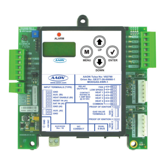
- Page 1 Factory Packaged Controls OE377-26-00060-1 (AAON Part No. V82790) MODGAS-XWR Controller Technical Guide...
-
Page 2: Table Of Contents
Factory Technical Support Phone: 918-382-6450 AAON is a registered trademark of AAON, Inc., Tulsa, OK. ® Controls Support Phone: 866-918-1100 White-Rogers is a registered trademark of Emerson Climate ®... -
Page 3: Overview & Features
OVERVIEW General Information Overview Features The OE377-26-00060-1 MODGAS-XWR Controller (AAON Part No. MODGAS-XWR Controller provides the following: V82790) is designed to be used with White-Rogers ® valves only. It will • Can control two (2) Gas Valves using input from modulate up to two (2) White-Rogers ®... -
Page 4: Installation & Wiring
Zone WIRING OVERVIEW & MODULE DIMENSIONS Zone Important Wiring Considerations & Module Dimensions Important Wiring Considerations 5. All wiring is to be in accordance with local and national electrical codes and specifi cations Please read carefully and apply the following information when wir- 6. -
Page 5: 1V1Ign1S 1 Valve, 1 Ignitor, 1 Stage Stand Alone Wiring
Expansion Module. (Figure 8, page 11). This configuration operates as Stand-Alone (Figure 2, below) or communicating with an AAON Unit Controller (Figure 9, page 12). If using an MHGRV-X Controller along with the MODGAS-XWR Controller in Stand-Alone, the SAT Sensor always attaches to the This confi... -
Page 6: 2V2Ign2S 2 Valves, 2 Ignitors, 2 Stages Stand Alone Wiring & Secondary Board Wiring
This configuration operates as Stand-Alone (Figure 3, below) or fi xed stages can be added by using the 12-Relay E-BUS communicating with an AAON Unit Controller (Figure 11, page 14). Expansion Module. (Figure 8, page 11). This confi guration is used to control two modulating gas valves (one on each header), in which the fi... - Page 7 XWR Controller in Stand-Alone, the SAT Sensor always attaches to the This configuration operates as Stand-Alone (Figure 4, below) or communicating with an AAON Unit Controller (Figure 12, page 15). Primary MODGAS-XWR Controller. Figure 4: Secondary Board 2V2IGN2S Stand-Alone Wiring Diagram...
-
Page 8: 2V1Ign1S 2 Valves, 1 Ignitor, 1 Stage Stand Alone Wiring & Secondary Board Wiring
Expansion Module. (Figure 8, page 11). This configuration operates as Stand-Alone (Figure 5, below) or communicating with an AAON Unit Controller (Figure 13, page 16). If using an MHGRV-X Controller along with the MODGAS-XWR Controller in Stand-Alone, the SAT Sensor always attaches to the This confi... - Page 9 XWR Controller in Stand-Alone, the SAT Sensor always attaches to the This configuration operates as Stand-Alone (Figure 6, below) or communicating with an AAON Unit Controller (Figure 14, page 17). Primary MODGAS-XWR Controller. Figure 6: Secondary Board 2V1IGN1S Stand-Alone Wiring Diagram...
-
Page 10: 2V2Ign1S 2 Valves, 2 Ignitors, 1 Stage Stand Alone Wiring
Expansion Module. (Figure 8, page 11). This configuration operates as Stand-Alone (Figure 7, below) or communicating with an AAON Unit Controller (Figure 10, page 13). If using an MHGRV-X Controller along with the MODGAS-XWR Controller in Stand-Alone, the SAT Sensor always attaches to the This confi... -
Page 11: Bus Expansion Board Wiring
STAND-ALONE WIRING 12 Relay E-BUS Expansion Module - Stand Alone 12 Relay E-BUS Expansion Module If communication is lost to the 12-Relay E-BUS Expansion Module, the 12-Relay E-BUS Expansion Module will turn off its relays and the MODGAS-XWR Controller will alarm and fall back to using only its The 12-Relay E-BUS Expansion Module can be used to provide addi- onboard stages. -
Page 12: 1V1Ign1S 1 Valve, 1 Ignitor, 1 Stage Communicating Wiring
This confi guration operates as Stand-Alone (Figure 2, page 5) or communicating with an AAON Unit Controller (Figure 9, below). NOTE: Up to 3 additional fi xed heat stages can be used by using Heat Relays 2, 3 & 4 below. If additional fi xed stages This confi... -
Page 13: 2V2Ign1S 2 Valves, 2 Ignitors, 1 Stage Communicating Wiring
This confi guration operates as Stand-Alone (Figure 7, page 10) or communicating with an AAON Unit Controller (Figure 10, below). NOTE: Up to 2 additional fi xed heat stages can be used by using Heat Relays 3 & 4 below. If additional fi xed stages are This confi... -
Page 14: 2V2Ign2S 2 Valves, 2 Ignitors, 2 Stages Communicating Wiring & Secondary Board Wiring
This confi guration operates as Stand-Alone (Figure 3, page 6) or communicating with an AAON Unit Controller (Figure 11, below). NOTE: Up to 2 additional fi xed heat stages can be used by using Heat Relays 3 & 4 below. If additional fi xed stages are This confi... - Page 15 The Four Modulating Valves Primary/Secondary This confi guration operates as Stand-Alone (Figure 4, page 7) or configuration is not supported when using I communicating with an AAON Unit Controller. communications. Figure 12: Secondary Board 2V2IGN2S Communicating Wiring Diagram MODGAS-XWR-1 Technical Guide...
-
Page 16: 2V1Ign1S 2 Valves, 1 Ignitor, 1 Stage Communicating Wiring & Secondary Board Wiring
AAON Unit Controller’s relays. This confi guration operates as Stand-Alone (Figure 5, page 8) or communicating with an AAON Unit Controller (Figure 13, below). For VCM-X Controllers, use an I C Cable connecting to the appropriate C port on the controller. - Page 17 The Four Modulating Valves Primary/Secondary This confi guration operates as Stand-Alone (Figure 6, page 9) or configuration is not supported when using I communicating with an AAON Unit Controller. communications. Figure 14: Secondary Board 2V1IGN1S Communicating Wiring Diagram MODGAS-XWR-1 Technical Guide...
-
Page 18: Inputs/Outputs
Zone INPUTS & OUTPUTS Zone Inputs and Outputs I/O Map Proof of Ignition 1 (PO-IGN1) The Proof of Ignition input is activated by a 24VAC signal supplied from the Ignition Module to enable the modulating Gas Valve 1 (and The following inputs and outputs are available on the MODGAS-XWR the modulating Gas Valve 2 in the 2V1IGN1S confi... -
Page 19: Operation Modes & Staging Configurations
E-BUS cable. ler via a modular cable), the MODGAS-XWR Controller will modulate the gas valve(s) to maintain the DISCHARGE setpoint confi gured on MODGAS-XWR Communicating with AAON the MODGAS-XWR Controller LCD display. The MODGAS-XWR Unit Controller Controller is activated by a 24VAC signal to the HEAT EN input. -
Page 20: Sequence Of Operations
SEQUENCE OF OPERATIONS Heating Mode Heating Mode 2V2IGN2S: The PID loop runs every 10 seconds and determines the modulation percentage for the one variable valve. Ignition Sequence for each Valve Then, the valve moves to the correct position. Only after the Confi... - Page 21 SEQUENCE OF OPERATIONS Valve Failure, Force Mode & Master vs. Normal Valve Failure 2V2IGN1S: Forcing stage 1 on forces Heat 1 & 2 on, and the screens following allow you to select the modulation percentage for the respective valve. Even though both valves are considered If a valve failure occurs, the board fails that stage and then continues one stage, since they operate on separate relays, the option to to the next available stage.
-
Page 22: Lcd Display Screens
LCD DISPLAY SCREENS Navigation Keys LCD Display Screen & Navigation Main Screens Map Keys Refer to the following map when navigating through the LCD Main Screens. The fi rst screen is an initialization screen. To scroll through The MODGAS-XWR Controller allows you to make confi guration <MENU>... - Page 23 LCD DISPLAY SCREENS Main Screens Map and MODGAS Screens Protected Screens Map Main MODGAS Screens Refer to the following map when navigating through the LCD Protected Refer to the following map when navigating through the Main Screens. <ENTER> <ENTER> Screens. From the MGAS XWR Screen, press the twice From the MGAS XWR Screen, press to scroll through the...
- Page 24 LCD DISPLAY SCREENS Main Menu and Status Screens FAIL_STATE: FAIL_STATE occurs when the supply air temperature MODE STATE rises above the high temperature cutoff in any of the operating modes HEAT or when the supply air temperature sensor cannot be detected while in either stand-alone mode.
- Page 25 LCD DISPLAY SCREENS Alarm & Setpoint Screens SAT FAIL ERROR: The Supply Air Temperature sensor has been SA TEMP disconnected for more than 60 seconds. This will cause the Heat to be XX.X disabled. This alarm will be disabled when the sensor is reconnected or detected.
- Page 26 LCD DISPLAY SCREENS Setpoint & Force Valve Screens STAGE 2 FORCE RESET SP ON/OFF/DISABLED 40-200°F 5-93°C Press the <UP> button to turn the Force Mode on. Press the <DOWN> RESET HEATING SUPPLY AIR SETPOINT button to turn the Force Mode off . If the screen says disabled, on/off selection is not possible.
- Page 27 LCD DISPLAY SCREENS Confi guration Screens Confi guration Screens Refer to the following map when navigating through the Confi guration <ENTER> Screens. From the CONFIG Screen, press to scroll through STAGES <UP> <DOWN> the screens and change setpoints. Use the arrow TOTAL 1 TO 19 <ENTER>...
- Page 28 LCD DISPLAY SCREENS Confi guration Screens TEMP SCL STG DOWN FAHRENHT or 1 TO 10 m CELSIUS TEMPERATURE SCALE STAGE DOWN DELAY Fahrenheit (default) or Celsius (Used in stand-alone mode only). Range is 1 or 10 minutes. Default is 1. VLV STRT STG UP 1 TO 10 m...
-
Page 29: Troubleshooting
TROUBLESHOOTING LED Diagnostics LED Diagnostics Communication LED COMM - This yellow LED will light up and blink when communications The MODGAS-XWR Controller is equipped with LEDs that can be are detected. If this LED never blinks, then there is no communication. used to verify operation and perform troubleshooting. - Page 30 TROUBLESHOOTING Troubleshooting Figure 16: MODGAS-XWR Controller LED Locations and Descriptions MODGAS-XWR-1 Technical Guide...
- Page 31 • Check COMM LED on MODGAS-XWR. mounted correctly in supply duct. • Verify 24 VAC power to all interconnected AAON • Remove SAT and GND wiring from the MODGAS- controllers. XWR and ohm sensor out (this may indicate open or •...
- Page 32 TROUBLESHOOTING Temperature Sensor Resistance/Voltage Chart Other Checks Temperature to Resistance/Voltage Chart Temp Temp Resistance Voltage @ 0-3.3V (SAT OPTIONS Jumper Setting 1) & (°F) (°C) (Ohms) Input (VDC) 0-5V (SAT OPTIONS Jumper Setting 2) Supply 20.0 12191 1.81 Air Temperature Sensor 20.6 11906 1.79...
- Page 33 TROUBLESHOOTING Temperature Sensor Resistance/Voltage Chart Temperature to Resistance/Voltage Chart Temperature to Resistance/Voltage Chart Temp Temp Resistance (Ohms) Voltage @ Temp Temp Resistance (Ohms) Voltage @ (°F) (°C) Input (VDC) (°F) (°C) Input (VDC) 37.8 6047 1.927 -23.3 93333 4.620 40.6 5453 1.805 -20.6...
-
Page 34: Appendix A - Supply Air Temperature Sensor Guide
Communication Mode the duct using the supplied sheet metal screws. Be sure When communicating with AAON Unit Controllers, the SAT Sensor the gasket is compressed to provide an air tight seal. will be connected to the Main Controller. The exception would be •... - Page 35 APPENDIX A SAT Sensor Wiring Guide & Jumper Settings SAT Wiring Conditions MODGAS-XWR ONLY MODGAS-XWR & MHGRV-X STAND-ALONE Install Supply Air Install Sensor in MODGAS-XWR and daisy-chain Sensor in MODGAS-XWR. it to the MHGRV-X. Set “SAT Options” Jumpers to “MODGAS X”. If connected to a MODGAS II Retrofi...
-
Page 36: Appendix B - Modgas-Xwr-1 Replacement Of Modgas-Xwr
APPENDIX B MODGAS-XWR-1 Replacement of MODGAS-XWR Step 4: Unplug the TB2 Input Terminal Block from the Replacing the MODGAS-XWR with the MODGAS-XWR and replug it into the MODGAS- MODGAS-XWR-1 XWR-1 board. Step 5: The retrofi t replacement involves a few easy steps. Refer to Figure Unplug the Ignition blocks and Valve headers from the 18, below. - Page 37 NOTES MODGAS-XWR-1 Technical Guide...
- Page 38 NOTES MODGAS-XWR-1 Technical Guide...
- Page 39 NOTES MODGAS-XWR-1 Technical Guide...
- Page 40 2425 South Yukon Ave • Tulsa, OK • 74107-2728 Ph: (918) 583-2266 • Fax: (918) 583-6094 AAON Part No.: V73440, Rev. 01B ® Printed in the USA • © November 2018 AAON • All Rights Reserved...
Need help?
Do you have a question about the OE377-26-00060-1 and is the answer not in the manual?
Questions and answers