Table of Contents
Advertisement
Advertisement
Table of Contents

Related Manuals for Monoprice MP Voxel Pro


Summary of Contents for Monoprice MP Voxel Pro
- Page 1 MP Voxel™ Pro Fully Enclosed 3D Printer P/N 44091 User's Manual...
-
Page 2: Table Of Contents
CONTENTS SAFETY WARNINGS AND GUIDELINES ........................... 4 CUSTOMER SERVICE ....................................6 PACKAGE CONTENTS .................................... 6 PRODUCT OVERVIEW ................................... 8 Front and Right Side View ................................8 Internal and Extruder Views ..............................9 Internal View ......................................10 SOFTWARE INSTALLATION ................................10 GETTING STARTED .................................... - Page 3 TECHNICAL SUPPORT ..................................32 SPECIFICATIONS ......................................33 REGULATORY COMPLIANCE ................................ 34 Notice for FCC ....................................34 RF Exposure Statement for FCC ............................35 ISED Statement ....................................35 EU Conformity with applicable directives ........................36 UK Conformity with the relevant Union harmonization legislation ............37 Disposal and Recycling Information ..........................
-
Page 4: Safety Warnings And Guidelines
SAFETY WARNINGS AND GUIDELINES Please read this entire manual before using this device, paying extra attention to these safety warnings and guidelines. Please keep this manual in a safe place for future reference. • This device is intended for indoor use only. •... - Page 5 • Take care to prevent damage to the power cord. Do not allow it to become crimped, pinched, walked on, or become tangled with other cords. Ensure that the power cord does not present a tripping hazard. • Never unplug the unit by pulling on the power cord. Always grasp the connector head or adapter body.
-
Page 6: Customer Service
If you have any problem with your order, please give us an opportunity to make it right. You can contact a Monoprice Customer Service representative through the Live Chat link on our website www.monoprice.com or via email at support@monoprice.com. - Page 7 1x Screwdriver 1x Clog Removal Tool 1x Allen Wrench 1x Packet of Grease 1x USB Flash Drive 1x Leveling Card 3x AC Power Cords 1x Spool Filament 1x User's Manual (US/UK/EU)
-
Page 8: Product Overview
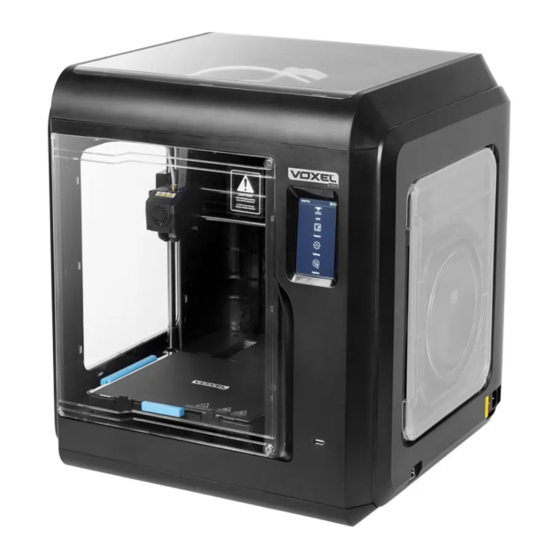
PRODUCT OVERVIEW Front and Right Side View 1. Power Switch 2. Power Connector 3. Filament Door 4. Filament Spool Holder 5. Filament Intake Cover 6. Front Door 7. Build Platform Base 8. Build Plate 9. Touchscreen Interface 10. USB Port 11. -
Page 9: Internal And Extruder Views
Internal and Extruder Views 12. Extruder 13. Filament Guide Tube Joint 14. Cable Slot 15. Extruder Cooling Fan 16. Model Cooling Fan 17. Buckle 18. Air Duct 19. Nozzle 20. Camera... -
Page 10: Internal View
You can also download it from the product page on the website. To locate the download file, navigate to https://www.monoprice.com, then type 44091 into the search bar, and hit ENTER. Scroll to the bottom of the page to find the Support Files section, which has the full manual, the FlashPrint software package, and any other related files. -
Page 11: Getting Started
GETTING STARTED 1. If you have not already installed the FlashPrint software package, install it now by SOFTWARE INSTALLATION following the instructions in the section above. 2. Ensure that the Power Switch on the printer is in the OFF (O) position. 3. - Page 12 5. Although the printer was fully calibrated at the factory, it may have gone out of calibration during the shipping process, so it is a good idea to do at least a single- point calibration. On the Touchscreen Interface, touch Maintain > Calibration > Normal Mode.
- Page 13 6. Open the Filament Door on the printer, then place a spool of filament on the Filament Spool Holder. 7. Remove the Filament Intake Cover, then insert the end of the filament into the filament intake. Push the filament into the feeding wheel until some resistance is felt.
- Page 14 9. The USB Flash Drive included with the printer has sample models preloaded. Insert the USB Flash Drive into the USB Port on the printer. On the Touchscreen Interface, touch Build > USB Device. The system will display the files on the flash drive. Touch a model image to display the file details, then touch the Build button to start printing the file.
-
Page 15: User Interface
USER INTERFACE This printer features a touchscreen menu system, which allows you to easily adjust the printer settings, select and print models, and perform basic maintenance. This section details key elements of the user interface, with instructions on how to perform basic functions. -
Page 16: Build
Build Perform the following steps to print one or more models. 1. Touch the Build icon on the Main Menu. The system will display the File Location Selection screen. 2. Touch the Local Files icon to select files stored in the printer's internal memory. - Page 17 3. The system displays the files as a series of thumbnail images of the finished print. Momentarily touch an image to display the File Details screen. Press and hold an image to enable multi-selection mode, which allows you to select multiple files for printing.
- Page 18 5. The Print Progress screen displays a progress bar with the remaining print time required. It also displays the extruder and build plate temperatures and target temperatures. While printing is in progress, the following actions are possible: Pause the print job. Resumes a paused print job.
-
Page 19: Preheat
Preheat Perform the following steps to adjust the target temperature and preheat the Extruder and/or Platform (build plate). 1. Touch the Prepare icon on the Main Menu. The system will display the Prepare Menu. 2. Touch the Preheat icon to adjust the extruder and/or build plate target temperatures. -
Page 20: Filament
Filament Perform the following steps to Load, Change, or Manually Change the filament used for printing. 1. Touch the Prepare icon on the Main Menu. The system will display the Prepare Menu. 2. Touch the Filament icon to display the Filament screen. 3. -
Page 21: Settings
the Extruder to the target temperature. Follow the on-screen instructions to remove the old filament, then insert the new filament into the filament intake until some resistance is felt, but do not push it into the tube. When filament comes out of the Extruder, loading is complete. - Page 22 to the farthest point of the left side or when the build plate is moved to the farthest point of the front side. Fan: Turns the Chamber Cooling Fan at the top of the printer on or off. Status: Displays the printer status, including the temperature, X/Y/Z position, etc.
- Page 23 Camera: Displays the Camera Control screen, which allows you to turn the camera on or off and display saved Photos and/or Videos. Light: Turns the light on the extruder on or off. FilamentDetect: Turns the filament check sensor on or off. PrinterName: Allows you to change the name of the printer.
-
Page 24: Maintain
Maintain 1. Touch the Maintain icon on the Main Menu. The system will display the Maintain screen. 2. You can perform the following actions on the Maintain screen: Upgrade: If you are connected to the internet, you will be prompted to upgrade the firmware, if a firmware update is detected. -
Page 25: Calibration
Calibration Although the printer was calibrated at the factory, it is a good idea to perform a calibration before you use the printer for the first time. You should also perform a calibration after changing the nozzle. There are two methods of performing calibration: Expert Mode and Normal Mode. In Expert Mode, you can manually adjust the distance between the nozzle and the build plate. - Page 26 In Normal Mode, the printer first performs an extruder calibration, then performs a full Nine Point Auto Calibration. The first point calculates the initial distance between the extruder and the built plate. You can use the buttons to adjust the Z-axis deviation value.
-
Page 27: Change Extruder
Change Extruder 1. After installing a new nozzle, set the compensation value for the temperature of the new nozzle, in the range 0 ~ 30 from the base value of 240. Note that the proper offset value for each extruder is printed on the bag. The default nozzle type installed on this printer is 0.4-240. -
Page 28: Maintenance Advice
Maintenance Advice The Maintenance advice screen displays a system FAQ, which informs you how to perform certain actions or helps with troubleshooting a problem. -
Page 29: Maintenance
MAINTENANCE HEPA Filter Replace the HEPA filter cotton every 2 weeks. Perform the following steps to replace the filter. 1. Open the Front Door and locate the Chamber Fan at the top of the printer. 2. Open the Chamber Cooling Fan cover, remove the old filter cotton and replace it with a new filter cotton. -
Page 30: Extruder Guide Rails
Extruder Guide Rails Apply some grease to the Extruder Guide Rails every other month to ensure smooth movement of the Extruder. Unclogging the Nozzle From time to time, the nozzle can become clogged. Perform the following steps to unclog the nozzle. 1. - Page 31 3. Squeeze the two Buckles on the Extruder, then remove the nozzle. 4. While still squeezing the two Buckles, fully insert the new nozzle, then release the Buckles. 5. Inspect the Buckles and compare their condition to the images below. The image on the right is what they look like when the nozzle is fully inserted into the Extruder.
-
Page 32: Technical Support
TECHNICAL SUPPORT Monoprice™ is pleased to provide free, live, online technical support to assist you with any questions you may have about installation, setup, troubleshooting, or product recommendations. If you ever need assistance with your new product, please come online to talk to one of our friendly and knowledgeable Tech Support Associates. -
Page 33: Specifications
SPECIFICATIONS 44091 Number of Extruders Positioning Accuracy X/Y Axis: 0.011mm, Z Axis: 0.0025mm Layer Resolution 100 ~ 400 microns Build Volume 220 x 200 x 250 mm Nozzle Diameter 0.4mm (default), 0.6/0.3 mm (optional) Build Speed 10 ~ 150 mm/sec 240°C (default) or 265°C (optional), Maximum Extruder Temperature depending on extruder... -
Page 34: Regulatory Compliance
Modifying the equipment without Monoprice's authorization may result in the equipment no longer complying with FCC requirements for Class B digital devices. In that event, your right to use the equipment may be limited by FCC regulations, and you may be required to correct any interference to radio or television communications at your own expense. -
Page 35: Rf Exposure Statement For Fcc
This FCC Part 15 radio device operates on a non-interference basis with other devices operating at this frequency. Any changes or modification to said product not expressly approved by Monoprice, including the use of non-approved antennas, could void the user's authority to operate this device. -
Page 36: Eu Conformity With Applicable Directives
This device meets the exemption from the routine evaluation limits in section 2.5 of RSS 102 and compliance with RSS 102 RF exposure, users can obtain Canadian information on RF exposure and compliance. Cet appareil est conforme à l'exemption des limites d'évaluation courante dans la section 2.5 du cnr - 102 et conformité... -
Page 37: Uk Conformity With The Relevant Union Harmonization Legislation
Monoprice™, Voxel™, the Voxel logo, and all Monoprice logos are trademarks of Monoprice Inc. Wi-Fi® and Wi-Fi Alliance® are registered trademarks of Wi-Fi Alliance.
Need help?
Do you have a question about the MP Voxel Pro and is the answer not in the manual?
Questions and answers