Table of Contents
Advertisement
Quick Links
Advertisement
Table of Contents

Related Manuals for Monoprice MP Education Guider II


Summary of Contents for Monoprice MP Education Guider II
- Page 1 MP Education Guider II 3D Printer P/N 30527 User's Manual...
-
Page 2: Table Of Contents
CONTENTS SAFETY WARNINGS AND GUIDELINES ............................5 CUSTOMER SERVICE ....................................6 PACKAGE CONTENTS ....................................6 PRODUCT OVERVIEW ....................................8 Front View........................................8 Top View .......................................... 8 Right Side View ......................................8 Rear View ........................................9 OSD MENU SYSTEM ....................................9 Top Menu ........................................ - Page 3 Setup WLAN Hotspot Screen ..............................17 UNPACKING ........................................18 HARDWARE ASSEMBLY ..................................20 LOADING FILAMENT ....................................21 UNLOADING FILAMENT ..................................22 BUILD PLATE LEVELING ..................................24 MP FLASHPRINT SOFTWARE ................................26 Installation ........................................26 Initial Setup ........................................ 27 Main Interface Overview ................................28 Loading a File ......................................
- Page 4 Wi-Fi Connection ....................................48 UPDATING THE FIRMWARE ................................49 PRINTING ..........................................50 Generating Gcode ....................................50 SPECIFICATIONS ......................................53 TECHNICAL SUPPORT ....................................54 REGULATORY COMPLIANCE ................................54 Notice for FCC ......................................54 Notice for Industry Canada ................................55 EU Declaration of Conformity ..............................55 WEEE Information ....................................
-
Page 5: Safety Warnings And Guidelines
SAFETY WARNINGS AND GUIDELINES Please read this entire manual before using this device, paying extra attention to these safety warnings and guidelines. Please keep this manual in a safe place for future reference. Take care to avoid touching hot parts, including heat blocks, extruder nozzle, and the extruded filament. -
Page 6: Customer Service
If you have any problem with your order, please give us an opportunity to make it right. You can contact a Monoprice Customer Service representative through the Live Chat link on our website www.monoprice.com during normal business hours (Mon-Fri: 5am-7pm PT, Sat-Sun: 9am-... - Page 7 1x Warning card 1x Lid 1x AC power cord 1x USB cable 1x Filament guide 1x Phillips 1x USB stick 1x Spool holder tube screwdriver 1x Unclogging pin 1x Allen wrench set 1x Package grease 1x Wrench tool 1x Solid glue...
-
Page 8: Product Overview
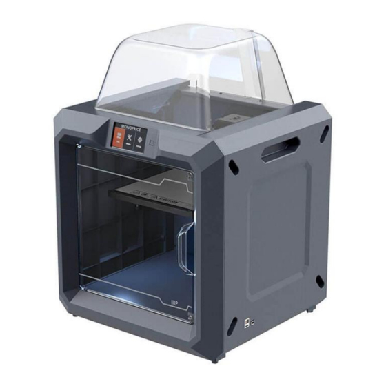
PRODUCT OVERVIEW Front View 1. Touch screen 2. Touch screen button 3. Nozzle 4. Z-axis guide rod 5. Build plate 6. Leveling knob Top View 7. Extruder 8. X-axis guide rod 9. Filament intake 10. Spring presser Right Side View 11. -
Page 9: Rear View
Rear View 14. Filament detector 15. Power switch 16. Power input OSD MENU SYSTEM Top Menu The Top Menu is displayed after the printer is powered on and initialized. Touch the Build button to enter the Build Menu. Touch the Preheat button to enter the Preheat Menu. -
Page 10: Print Menu
Print Menu The Print Menu is displayed after selecting a print file from internal memory or the memory stick. The print filename is displayed along with an estimate of the amount of time the print process will consume. Touch the Build button to start printing the loaded print file. -
Page 11: More Menu
More Menu The More Menu is displayed by touching the More button on the Print Progress Screen. Touch the Filament button to change filament during printing. Note that the print must be paused first. Touch the Back button to return to the Print Progress screen. -
Page 12: Preheat Temperature Screen
Preheat Temperature Screen The Preheat Temperature Screen is displayed by touching one of the Temperature buttons on the Preheat Menu. Touch an individual digit to select the digit to change. Touch the - button to decrease the value of the highlighted digit. ... -
Page 13: Tools Menu
Tools Menu The Tools Menu is displayed by touching the Tools button on the Top Menu. Touch the Filament button to load or unload filament. Touch the Level button to level the build plate. Touch the Home button to move the extruder to the home position. -
Page 14: Setting Menu
Touch the Z- button to lower the build plate. Touch the Back button to return to the previous menu. Setting Menu The Setting Menu is displayed by touching the Setting button on the Tools Menu. Touch the Language label to select the language for the OSD Menu System. -
Page 15: Status Screen
Touch the Factory Reset label to reset the printer's settings to their factory default values. Touch the Update label to update the printer's firmware. Touch the Up button to display the first page of the Setting Menu. ... -
Page 16: Wifi Screen
WiFi Screen The WiFi Screen is displayed by touching the WiFi label on the Setting Screen. The Wi-Fi® function allows you to connect the Guider II to a local Wi-Fi Access Point (AP)/hotspot, i.e., the one your computer is normally connected with. You can then connect to the printer in MP FlashPrint in Station Mode (STA) without changing your computer's network settings ... -
Page 17: Wlan Hotspot Screen
WLan Hotspot Screen The WLan Hotspot Screen is displayed by touching the WLan hotspot label on the Setting Menu. The MP Guider II printer contains a built-in Wi-Fi® radio, which can be configured as a Wi-Fi Access Point (AP)/hotspot. You can then connect to the printer in MP FlashPrint by changing the Wi-Fi connection on your computer to the Wi-Fi address of the printer. -
Page 18: Unpacking
UNPACKING 1. Place the box on a flat, clean work surface. 2. Open the box. Remove the two pieces of styrofoam packing, then lift the printer out of the box and place it on the work surface. 3. In the bottom of the carton you can find a spool of filament, the spool holder, a power cord, a USB cable, a filament guide tube, a glue stick, and a tool bag containing a USB stick, two Allen wrenches, a stamping wrench, an unclogging tool, a package of grease, and a screwdriver. - Page 19 5. Remove the styrofoam packing from the top of the printer. 6. Cut the four zip ties that hold the guide rods in place. Manually move the extruder to ensure that it moves freely along the guide rods. 7. Remove the top cover from inside the printer. Congratulations, you have successfully unpacked your new printer!
-
Page 20: Hardware Assembly
HARDWARE ASSEMBLY Perform the following steps to perform final assembly. 1. Insert the tab on the filament holder into the hole on the back of the printer, as shown in the images below. 2. Place the spool of filament on the filament holder. Thread filament through the filament detecting mechanism on the rear of the printer. -
Page 21: Loading Filament
4. Insert the filament guide tube into the filament detection mechanism. 5. Ensure the power switch is in the OFF position. Plug one end of the included power cord into the power input on the printer, then plug the other end into a nearby AC power outlet. -
Page 22: Unloading Filament
3. Touch the Filament button, then touch the Load button. The printer will start heating the extruder and platform. 4. Once the target temperature is reached, the printer will beep to let you know it is ready for the next step. Insert the filament into the filament intake hole on the top of the extruder. - Page 23 2. Wait for the printer to stabilize, then touch the Tools button on the Top Menu. 3. Touch the Filament button, then touch the Unload button. The printer will start heating the extruder and platform. 4. Once the target temperature is reached, the printer will beep to let you know it is ready for the next step.
-
Page 24: Build Plate Leveling
BUILD PLATE LEVELING The Guider II features a 3-point intelligent leveling system, which gives clear and comprehensive feedback. There are three, spring-loaded knobs under the build plate. Turning the knobs counterclockwise (when viewed from above) increases the distance between the build plate and the extruder nozzle. Turning them clockwise (when viewed from above), decreases the distance between the build plate and the extruder nozzle. - Page 25 3. Turn the three spring-loaded knobs under the Build Plate counterclockwise until you cannot turn them anymore, then touch the OK button. 4. Wait while the printer checks the distance between the build plate and the extruder nozzle at the first leveling point. 5.
-
Page 26: Mp Flashprint Software
6. Touch the Verify button. The printer will check the distance again. 7. If the distance is correct, touch the OK button to proceed to the next leveling point. If not, follow the onscreen instructions until the distance is correct and the OK button is displayed. -
Page 27: Initial Setup
Once you have located the software installation package, run the application and follow the onscreen installation instructions. Initial Setup Once MP FlashPrint has been installed, double-click the application shortcut to start the program. If this is the first time the program has been run, you will be presented with a dialog asking you to select the Machine Type. -
Page 28: Main Interface Overview
Main Interface Overview The screenshot below shows the three main elements of the software - the Menus, the Icons, and the Build Platform. The icons have the functions listed in the table below. Icon Function Loads a model or Gcode file. MP FlashPrint supports .STL, .OBJ, and .FPP model files. -
Page 29: Loading A File
Views the MP FlashPrint home screen from one of six viewing angles. View Moves the model around on the X/Y plane. Hold the SHIFT key then click to move the mode along the Z axis. Move Turns and rotates the model. Rotate Scales the size of the model. -
Page 30: Generating A Model
Click File > Load File, then select the file. Click File > Load Examples to load one of the sample files. Click File > Recent Files, then select the file from the list of recently used files. ... - Page 31 The following screenshots illustrate the five basic shapes. Plane Tube Canister...
-
Page 32: Changing Views
Lamp Seal Changing Views You can change the camera angle in relation to the model and build area using a variety of methods. Drag: Click the View icon, then drag the camera using one of the following methods. Left click and hold, then move the mouse. ... - Page 33 Rotate: Click the View icon, then rotate the camera using one of the following methods. Right click and hold, then move the mouse. Hold down the SHIFT key, left click and hold, then move the mouse. Scale: Scroll the mouse wheel up or down to zoom the camera in or out. Set View: You can select one of six preset camera angles using one of the following methods.
-
Page 34: Model Manipulation
Model Manipulation You can manipulate the model using a variety of methods. Move: Click on the model to select it. You can then move it around the build area in a variety of ways. To move the model horizontally in the X/Y plane, left click and hold on the model, then move the mouse. - Page 35 Cut: Click the model to select it, then double-click the Cut icon to set the cut plane in a variety of ways. Left click and drag the cursor across the model to set the cut angle. Select the X Plane option to cut the model vertically. ...
-
Page 36: Supports
Supports Because 3D printing is an additive process, each layer of filament needs a base to build on. The printer can gradually increase the layer size, so long as the overhang angle is less than about 45 degrees. Otherwise, you need to create support elements to serve as the base for adding additional layers. - Page 37 Support Options: Click the Support Options button to display the Support Options dialog. You can select Treelike or Linear supports. Treelike supports are built at angles, while Linear supports are linear, vertical supports for the overhanging elements. When you click the OK button, the software will generate the appropriate support structures.
-
Page 38: Printing A Model
Delete Supports: Click the Delete Supports button to remove individual supports. Click the cursor on the support you want to remove to highlight that support and all subnode supports, then click the left mouse button to delete the highlighted support. Printing a Model Click the Print icon on the main interface to slice the model and print the resulting Gcode file, either directly from MP FlashPrint or by first exporting it to the USB stick. - Page 39 Wall: Check the Wall box to help clear leaking filament from a second extruder during dual color printing. Brim: Check the Brim box to print a ring of filament around the model to help prevent warping and assist with bed adhesion. Resolution: For ABS and PLA printing, you can choose Low, Standard, or High resolution.
- Page 40 option is for all infill, while the Every N Inner Layers affects only the inner infills, which generally saves print time. Speed: Click the Speed tab to reveal the speed settings. Print Speed: Determines the speed that the extruder moves while printing filament.
-
Page 41: File Menu
File Menu The File Menu contains the following options. New Project: Click File > New Project or press CTRL+N to create a new, blank project. A project saves in one place all the models in the scene, including positions, supports, and settings. -
Page 42: Edit Menu
Edit Menu The Edit Menu contains the following options. Undo: Click Edit > Undo or press CTRL+Z to undo the last change. In most cases, you can undo multiple changes, one at a time. Redo: Click Edit > Redo or press CTRL+Y to redo the last change that was undone. In most cases, you can redo multiple undos. -
Page 43: Print Menu
Print Menu The Print Menu contains the following options. Connect Machine: Click Print > Connect Machine to establish a USB or Wi-Fi® connection to the printer. This option is not available if the printer is already connected. Disconnect: Click Print > Disconnect to break a connection with the printer. This option is not available if there is no connection with the printer. -
Page 44: Tools Menu
Tools Menu The Tools Menu contains the following options. Control Panel: Click Tools > Control Panel to modify the printer's settings from within MP FlashPrint. Note that if you are not connected to the printer, you will be prompted to do so before the Control Panel can be displayed. ... - Page 45 Limit Switch: Displays the status of the limit switches on each axis. If the extruder or build plate are not moved to its maximum positions, the status will show Not Triggered in green. If the extruder or build plate has been moved to its maximum position, the status will show Triggered in red.
-
Page 46: Help Menu
Help Menu The Help Menu contains the following options. First Run Wizard: Re-runs the wizard that automatically runs the first time MP FlashPrint is run. Help Contents: Allows you to read the help files. Feedback: Allows you to submit feedback. Check For Updates: Checks for MP FlashPrint updates. -
Page 47: Wlan Hotspot Connection
WLAN Hotspot Connection Perform the following steps to connect your PC to the Guider II printer using the printer's built-in WLAN hotspot. 1. Power on the printer and your computer. 2. On the printer, select Tools > Setting > WLan hotspot > WLan hotspot ON. 3. -
Page 48: Wi-Fi Connection
Wi-Fi Connection Perform the following steps to connect your PC to the Guider II printer using an existing Wi-Fi® access point. 1. Power on the printer and your computer. 2. On the printer, select Tools > Setting > WiFi > WiFi ON. 3. -
Page 49: Updating The Firmware
UPDATING THE FIRMWARE Each time you start FlashPrint, it will automatically detects and downloads the up-to-date firmware. If an update is available, a dialog box will appear to remind you of the update. Perform the following steps to update the firmware. 1. -
Page 50: Printing
PRINTING Perform the following steps to print a model on the Guider II printer from a Gcode file saved to the USB stick. Generating Gcode 1. Plug the USB stick into a USB port on your computer. 2. Double-click the MP FlashPrint shortcut to launch the software. 3. - Page 51 6. Click the Print icon, then change the settings as appropriate for your filament type and model. Preview: Check the Preview box if you want to preview the model after slicing is done. Print When Slice Done: Because we are printing from the USB stick, uncheck this box to save the Gcode file to the USB stick.
- Page 52 11. Touch the Build button on the printer display. 12. Touch the USB Stick option, then locate and load your model file. 13. Touch the Build icon to begin printing. The printer will begin heating the extruder, then will begin printing once the target temperature is reached. Touch the Stop button at any time to cancel the print.
-
Page 53: Specifications
SPECIFICATIONS Model 30527 Printer Name MP Guider II Number of Extruders Print Technology Fused Filament Fabrication (FFF) Screen Type 5.0" color IPS touch screen Build Area 280 x 250 x 300 mm Layer Resolution 0.05 - 0.4 mm Build Accuracy ±0.2mm Positioning Accuracy XY Axis: 0.011mm, Z Axis: 0.0025mm... -
Page 54: Technical Support
TECHNICAL SUPPORT Monoprice is pleased to provide free, live, online technical support to assist you with any questions you may have about installation, setup, troubleshooting, or product recommendations. If you ever need assistance with your new product, please come online to talk to one of our friendly and knowledgeable Tech Support Associates. -
Page 55: Notice For Industry Canada
Cet appareil numerique de la classe B est conforme a la norme NMB-003 du Canad EU Declaration of Conformity Monoprice, Inc. declares the product described within this user guide or manual is in compliance with below applicable directives. The full text of the EU Declaration of Conformity is available at the following internet address: https://www.monoprice.com/product?c_id=107&cp_id=10724&cs_id=1072403&p_id=30525... -
Page 56: Weee Information
Electric and Electronic Equipment (WEEE) This document contains important information for users with regards to the proper disposal and recycling of Monoprice products. Consumers are required to comply with this notice for all electronic products bearing the following symbol: For Consumers in the European Union: This EU Directive requires that the product bearing this symbol and or its packaging must not be disposed of with unsorted municipal waste. -
Page 57: Safety Notice
Safety Notice WARNING: Do not use this product near water, for example, in a wet basement or near swimming pool or in an area where accidental contact with water or liquid might occurs WARNING: Avoid using this product during an electrical storm. There may be a remote risk of electric shock from the surge caused by lightning WARNING: The external power adapter or AC power cord is the equipment's disconnection device.
Need help?
Do you have a question about the MP Education Guider II and is the answer not in the manual?
Questions and answers